JCM Technologies Free30r Instructions for use

electronic solutions for gates, doors
and access control
Free
hands free system
for vehicles and people
Applications manual for Free system
be a step ahead with technology and imagination
jcmtechnologies

be a step ahead with technology and imagination
jcmtechnologies

Free
hands free system for vehicles and people
1. Introduction. 04
1.1 Description of the system. 04
1.2 Requirements of the normative. 07
2. Functioning. 08
3. Installation. 10
3.1 Installation and conections Trigger Free 15R, Free 30R and Free 50R/RS. 11
3.2 Installation Tag Free T. 12
4. Programming. 13
4.1 Tag Programming in the Receiver. 13
4.2 Trigger Programming. 14
5. Applications. 15
5.1 Applications in shops and catering. 15
5.2 Applications in offices. 15
5.3 Industrial applications. 15
5.4 Town plannig applications. 16
5.5 Residential and Community Applications. 16
6. Recommendations. 17
7. Synoptic of receivers compatible with Free system that works with groups. 18
8. Synoptic of receivers compatible with Free system that works only with one group. 19

be a step ahead with technology and imagination
jcmtechnologies
4
1Introduction
Free
applications manual for Free system
The HANDS-FREE system will open all the doors without you having to press any control button.
The FreeT group of products is designed for use with domestic, commercial and even industrial ve-
hicles and for individual use by pedestrians in private and professional areas, allowing for the access
control of people and goods.
FreeTH is a multi-use product, especially designed for controlling the movements of the people, lo-
cating people in buildings, presence control, emergency and evacuation plans, etc., in companies,
offices, banks, sports centres, hospitals and geriatric centres, among others.
1.1 System description
FreeTH
FreeT
Free50r
Free30r
Free15r
Free50rs

be a step ahead with technology and imagination
jcmtechnologies 5
Introduction 1
Free
applications manual for Free system
Nominal range: 100 meters.
Transmission frequency: 868 MHz.
Power: 1 x 3Vdc batteries type CR2032.
Batteries last for approximately 2 years.
Acoustic operating indicator for low battery, signal transmission and programming.
Push-button inlet for voluntary activations.
Operating temperature –20ºC a + 55ºC.
ABS plastic case.
Size: 65 x 55 x 10 mm.
Nominal range 100 meters.
Transmission frequency 868 KHz.
Power: CR2032-type 3Vdc battery.
Batteries last for approximately 2 years.
LED operating indicator for low battery, signal transmission and programming.
Operating temperature -20°C a + 55°C.
PC IP66 plastic case.
Size: 48 x 48 x 12 mm.
System description 1.1
FreeT(TAG)
FreeTH (TAG)

6
1Introduction
Free
applications manual for Free system
1.1 System description
Free15r - Free30r (TRIGGER)
Free50r - Free50rs (TRIGGER)
Free15r nominal range: 1.5 metres.
Free30r nominal range: 3 metres.
Transmission frequency: 125 KHz.
Power: 12/24Vac/dc.
LED operations indicator.
Button input for channel and/or group programming.
Pre-wired connection.
Operating temperature -20°C a + 55°C.
ABS IP66 plastic case.
Size of Free30r: 205 x 183 x 14 mm.
Size of Free15r: 87 x 78 x 15 mm.
Stand alone (no connections between Free antennas and other devices)
Triggers with activation input
Free50rs nominal range: 5 metres.
Free50rs nominal range: 5 metres. Fitted with an adjustable presence
sensor capable of detecting a moving body from 2.5 to 6.5 metres.
Transmission frequency: 125 KHz.
Power: 230Vac.
LED operations indicator.
Button input for channel and/or group programming.
Pre-wired connection.
Operating temperature -20°C a + 55°C.
ABS IP66 plastic case.
Size of Free50r: 394,4 x 310,5 x 41,6 mm.
Size of Free50rs: 394,4 x 310,5 x 78,7 mm.
Stand alone (no connections between Free antennas and other devices)
These triggers allow a button which permits the programming with a constant pressure of this button. This allows the selec-
tion of the group of the trigger as well as the receiver activation channel. This information will be given by the TAG.
be a step ahead with technology and imagination
jcmtechnologies

7
Introduction 1
Free
applications manual for Free system
Requirements of the normative 1.2
The applicable directives to this system are:
• Radio and Terminal Telecommunications Equipments Directive 1999/5/CEE
•Low voltage Directive 2006/95/EC
•Electromagnetic compatibility Directive 2004/108/EC
Some of the requirements of the applicable harmonized standards are shown below.
In accordance with the European low voltage directive, you are informed of the following requirements:
•For permanently connected equipment, an easily accessible connection device must be incorporated into the cabling.
•This equipment must always be installed in a vertical position and firmly fixed to the structure of the building.
•This equipment can only be handled by a specialist fitter, by maintenance staff or by a suitably trained operator.
•The instructions for use of this equipment must always remain in the possession of the user.
JCM TECHNOLOGIES, S.A. declares herewith that the products FreeT, FreeTH, Free15r, Free30r, Free50r, Free50rs, comply
with the requirements of the 1999/5/CEE R&TTE Directive, 2004/108/EC Directive on electromagnetic compatibility and
2006/95/EC on low voltage, insofar as the product is used correctly.
CE DECLARATION OF CONFORMITY
See website: www.jcm-tech.com
be a step ahead with technology and imagination
jcmtechnologies

8
2Functionning
Free
applications manual for Free system
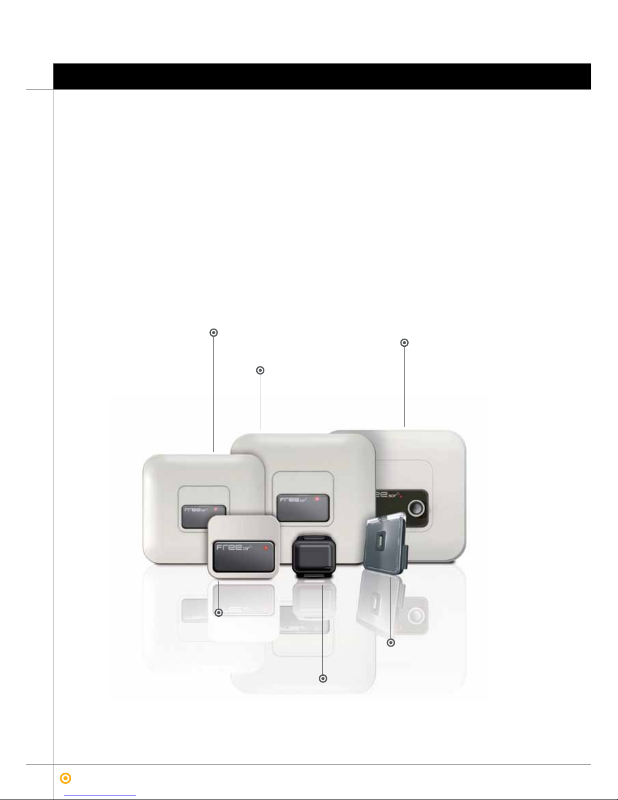
Hands Free functionning
Free system works as hands free. While entering with FreeT/TH device in the activation area of the Free50r or Free50rs trigger,
it activates itself sending a radio signal to the receiver.
To activate the Tag once inside the activation area, or to get out of it, you could always press the push button of FreeT if it is
needed at any time.
The activation area of the trigger is about 1,5 meters in Free15, 3 meters in Free30 and 5 meters in Free50 version.
The tag range is up to 100 metres in open spaces.
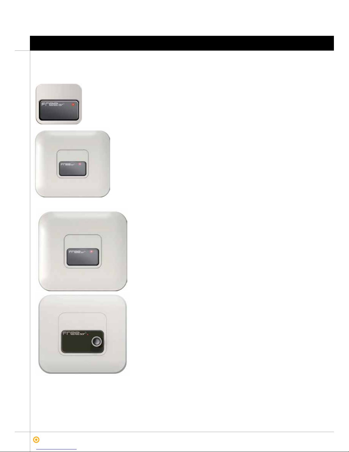
Free50r can be installed both, with or without presence detector. If the choiced option is to install it without presence detector,
to joint the presence cable with the mass cable (see Installation section) is compulsory in order to be transmitting all the time.
When the trigger is connected to a presence detector, either photocell or magnetic detector, they must be connected the pre-
sence cable and the mass cable (see Installation section). In that way, when the detector detects presence, the trigger starts
trasnmitting and the Tag can be activated while entering in the activation area sending its signal to the receiver. By contrary, if
presence is not detected, the trigger do not activates itself not allowing the Tag activation once in the trigger’s activation area.
Free50rs version incorporates a sonar by default, that realizes the presence detector function. This sonar works with a non
audible ultrasound at 42KHz. It can detect small objects a very few meters and big ones in longer distances. To optimize the
detection, the obstacle should be at 90 degrees respect the sonar.
Sonar distances
PEOPLE CARS WALL
3,5 TO 5 METERS IN FRONT 5,0 TO 5,5 METERS - SIDEWAYS 6,0 TO 6,5 METERS 7 METERS
Tag code + Trigger Group +
Activation Channel
Tag code + Trigger Group +
Activation Channel
Tag code + Trigger Group +
Activation Channel
1.5 m - 125 KHz
100 m
3 m - 125 KHz 100 m
100 m
5 m - 125 KHz
be a step ahead with technology and imagination
jcmtechnologies

9
Functionning 2
Free
applications manual for Free system
Groups concept
FreeT is able to manage up to 21 diferent doors while Free TH is able of 28. Ideally for apllications of fast doors and wandering
control.
Manual functionning
While pressing the button, tag works exactly the same as a traditional transmitter. It only sends the TAG code plus Open Group
(Group 0 by default) and channel 1. So every receiver in which this information has been learned will accept the TAG information
and will activate the outputs.
The difference between both ways of functionning of Free system lies on the quantity of information is transmitted by the TAG
to the receiver. While working as hands free, trigger plus tag information are sent, but while working manually, only an open
group plus tag information are sent.
FreeT tag also works though a push button in difference from FreeTH. In this very case, the fuctionning is manual.
Tag code + Trigger Group
+ Activation Channel
Channel 2 - Group 1
Channel 3 - Group 1
Channel 2 - Group 1
Channel 4 - Group 1
Group 1
Channel 1 - Group 0
Channel 2 - Group 2
Channel 3 - Group 2
Channel 4 - Group 2
Group 2
be a step ahead with technology and imagination
jcmtechnologies

10
3Installation
Free
applications manual for Free system
Free system offers to the installer a fast and comfortable way to install the product.
Trigger is made by a compact plastic housing in its front with a cable output in its rear part (1).
A trim sticker (2) is given so that led and programming push are protected.
Free15r has been designed to be installed directly on the wall or built in. Fixation is made with two screws separated among
themselves by 60mm (3).
Trigger push button allows the programation of the groups and channels of activation (4).
Trigger led is visible through the window of the sticker (5).
Triggers dimensions are 87x78x15 mm (Free15r); 205x183x14 mm (Free30r); 394,4x310,5x41,6 mm (Free50r) and
394,4x310,5x78,7 mm (Free50rs ). This allows Free15r to be installed in a standard electric box, either wall mounted as built
in, both interior or exterior of the installation.
To a better adjustment of the activation area, Free30r is supplied together with an orientable wall support. This support is
also compatible with Free15r, but in this very case, it must be acquired as accessory.
Free50r / rs are also delivered with an orientable wall support, but different from the previously mentioned support.
Triggers are completely independant from the receiver. The unique thing they need for work is power.
There are two ways to install the triggers, as individual or collective.
Free50r / Free50rs support.Free15r / Free30r support.
3.1 Installation and connections Free15r, Free30r and Free50r/rs
32
5
4
1
be a step ahead with technology and imagination
jcmtechnologies

11
Installation 3
Free
applications manual for Free system
Installation and connections Free15r, Free30r and Free50r/rs 3.1
Individual installation
Free15r and Free 30r must be plug to a 12/24ac/dc power supply as shown in the following scheme. Free 50r / rs must use a
230V power supply instead.
In Free50r, if a presence detector is not used, the presence detector cable (red) must be connected to the mass cable (black),
that in this case simulates an all time presence detection. Moreover of shorting the syncronism signals of IN and OUT.
Collective Installation
In a collective installation of Free15r / Free30r, these must be connected in series and four units as maximum can be connec-
ted. To ensure a perfect functionning of these triggers, the OUT sincronism signal must be connected to the following IN one,
and once we arrive to the last trigger, we have to link the IN signal of this last one to the OUT signal of the first one.
Free50r and Free50rs triggers must be connected in series and a maximum of 4 can be connected. In order to get a proper
funtioning, OUT sincronism signal must be connected to IN sincronism signal until the last trigger is connected, in which IN
signal must be linked with OUT signal from the first trigger. In this version first trigger ground signal (GND) must be connected
to the next trigger ground signal until the last one is connected. If a presence detector is not installed, presence signal must be
linked to the ground cable (GND) of the same trigger.
230 V
230 V
In PresenceOut GND
Signal Cable Color
+ (12/24V ac/dc) Red
- (GND) Black
Sync IN Green
Sync OUT White
Signal Cable Color
Presence Red
- (GND) Black
Sync IN Green
Sync OUT White
Free15r
Free30r
Free50r
Free50rs
230 V
230 V
In Out Presencia GND
230 V
In Out Presencia GND
230 V
In Out Presencia GND
230 V
In Out Presencia GND
Free15r · Free30r Free50r · Free50rs
In Out
12/24V
ac/dc
+GND
-
GND
-
12/24V
ac/dc
+
Auxiliary
power
supply
In Out In Out In Out In Out
12/24V
ac/dc
+GND
-
12/24V
ac/dc
+GND
-
12/24V
ac/dc
+GND
-
12/24V
ac/dc
+GND
-
12/24V
ac/dc
+GND
-
be a step ahead with technology and imagination
jcmtechnologies

12
3Installation
Free
applications manual for Free system
3.2 TAG FreeT Installation
FreeT ofers to the user a very simple and comfortable way of installation, either vehicle, clothe or as keyholder.
To install it in the vehicle, there is a car holder. It must be sticked to the car by removing the sticker protection. We recommend
to stick it in a plane surface.
For a correct application, the surface must be clean while sticking the car holder.
Just in case that the car holder is placed in the windshield, we recommend to allocate it in the dotted area to guaranty a better
range in athermal windows.
To place the TAG in:
· Car Holder, only slide the Tag through the car holder guides.
· Clothes; pockets, belts... we facilitate a cloth holder that works as clamp between the Tag and the cloth. To subject the
Tag to it, only to put the plastic of the clamp in the Tag is needed.
The Tag also can be used as keyholder. To do it, only to put a ring in the Tag slot is required.
Both, clothe and car holder are supplied with the FreeT.
Clip
Tag holder for car
dashboards.
be a step ahead with technology and imagination
jcmtechnologies

13
Programación 4
Free
applications manual for Free system
Programming TAG in receivers 4.1
TAG can be programmed in the receiver manually or by using the programming tool Assistant or PROG-MAN.
Manual Programming
To program or learn the FreeT in a receiver, the programming function in the receiver must be activated by the Prog button.
Once the receiver has emit one whistle, that means programming is open, the push button of the Tag must be pressed or also
canbe aproach the Tag to a trigger in order to make the Tag to activate itself. The TAG emits the information to the receiver
together with a whistle that confirms Tag programming in the receiver. To finish this operation, you can either press the Prgo
button or wait to the receiver to get out of programming status automatically.
Programming with ASSISTANT or PROG-MAN
To program or learn the FreeT in the receiver through programming tools it must be assigned to the receiver in the ASSISTANT
or PROG-MAN the Tag code. By this, when Tag will get closer to the trigger o the push button of the Tag will be pressed, the
receiver will recognize the FreeT.
Also code reservation o substitution is valid.
be a step ahead with technology and imagination
jcmtechnologies

14
4Programming
Free
applications manual for Free system
4.2 Trigger programming
The trigger allaows to program Codes and Groups. Both are done thanks to the push button and following the color indications
given by the led.
Channels: 4 channels maximum
To start to program the channels of the trigger, the push button of it must be pressed. Then the led will start blinking slowly and
showing a red color. Each blink equals a channel. To selec the channel, it must be released the push button once we arrive to
the desired channel.
Red led will remain in red showing that the channel has been selected.
Channel 2 programming example:
Groups: 7 groups maximum
To program a group, the functionning is quite similar to the channels procedure. Push button of the trigger must be pressed. Led
will show the red slowly blinkings of the channels configuration. But we must keep pressing, then led will show green blinkings
in a really fast way. This meants that groups programming is comming. Once the fast green blinking are over, the slowly green
blinking appears. Each slowly green blinking means a group. To select a group, it must be released the push button once the
group desired is achived.
Green led will remain for a while indicating that the group has been selected properly.
Functionning mode
Press push button to
select the channel
Stop press
Channel 1 Channel 2 Channel 3 Channel 4
Functionning mode
Keep pressing the
push button to select
the group
Press push button to
select the channel
Press the push button
to select the group
Fast flashings
Stop press
Channel 1
Group 1
Channel 2
Group 2
Channel 3
Group 3
Channel 4
Group 4
be a step ahead with technology and imagination
jcmtechnologies

15
Applications 5
Free
applications manual for Free system
Application in shops and hospitality 5.1
Application in offices 5.2
Application in Industry 5.3
FreeT has been though to be used in applications such residential, community, shopping, offices, restaurants, industry, institu-
tions and twon planning.
FreeTH has been though to be used in hospitals, offices, restaurants and industries.
be a step ahead with technology and imagination
jcmtechnologies

16
5Applications
Free
applications manual for Free system
5.4 Application in barriers
5.5 Application in residential and community doors
be a step ahead with technology and imagination
jcmtechnologies

17
Recommendations 6
Free
applications manual for Free system
To ensure an optimal functionning of the Free System, from JCM we do recommend to follow the below advises
•Do not install the trigger in metallic surfaces. If so, the range can be affected.
•To change the batteries every 18 months or at least when the Tag point it out by acustic or lighting signal
•As in GoPro, do not use Go transmitters in installations that a FreeT / TH are installed as FreeT / TH equals a GoPro.
be a step ahead with technology and imagination
jcmtechnologies

18
7Receivers allowed for the groups
Free
applications manual for Free system
Resume of receivers which can work with FREE system GROUPS
be a step ahead with technology and imagination
jcmtechnologies
RECEIVERS
MOTION JCM
Receiver Applications Description Compatible with
GROUPS system
BASE30
868 MHz radio
receiver, 1 or 2
relays, 30 codes.
1 impulse relay channel. / 2 channel (Relay 1 impulse
and relay 2 selectable impulse/bi-stable).
Built-in antenna.
Fixed 30 code memory.
Power supply: 12/24Vac/Vdc
Transmitter group
self-learning
BASE500
868 MHz radio
receiver, 1 or 2
relays, 500 codes.
1 impulse relay channel. / 2 channel (Relay 1 impulse
and relay 2 selectable impulse/bi-stable).
Built-in antenna.
Removable 500-code memory.
Power supply: 12/24 Vac/Vdc.
Compatible
with groups
STICK30
Pluggable receiver
card, 2 channels,
30 codes.
2 channel (Relay 1 impulse and relay 2 selectable
impulse/bi-stable).
Built-in antenna.
Fixed 30 code memory.Pluggable in control panel.
Power supply: 12Vdc from the panel.
Transmitter group
self-learning
STICK500
Pluggable receiver
card, 2 channels,
500 codes.
1 impulse relay channel (modificable a biestable con
herramienta de programación ASSISTANT).
Built-in antenna.
Removable 500-code memory.
Pluggable in control panel.
Power supply: 12Vdc from the panel.
Compatible
with groups
ST500 Active antenna with
built-in 868 MHz.
2 impulse relay channels (can be modified to bi-stable
using the ASSISTANT programming tool).
Removable 500-code memory.
Antenna connector.
Dead-man program for transmitters which work this way.
Pluggable in ASSISTANT and PROGMAN programming
tools.
Group self-learning
CONNECT
Multi-protocol
868 MHz radio
receiver.
Allows for the use of 868 MHz transmitters with any
control panel operating with Wiegand or Clock&Data
protocol.
Allows for single or multi-channel configuration.
Power supply: 12Vdc.
Anti-passback input.
Built-in antenna.
Group self-learning
ACTIVA GO Active antenna with
built-in 868 MHz.
Allows for the reception points to be multiplied and to
increase the range of the system, connecting several
antennas in parallel.
Works as a buffer, receiving codes and re-transmitting
them to the receiver by cable.
Can be used as an interface with DCS equipment.
Power supply: 12Vdc.
Maximum cable length: 200 m.
Group self-learning
RBMOTION
Radio communication
system for safety
bands with built-in
MOTION 868 MHz
receiver.
Equipment comprising:
RADIOBAND receiver (2 relays with selectable operating
mode. Can behave like a safety edge or a closed safety
contact).
6-RADIOBAND/TBX transmitter memory.
MOTION 868 MHz receiver (2 relays ( Relay 1 impulse
and relay 2 selectable impulse/bi-stable), fixed 30 code
memory.
Power supply: 12/24Vac/dc.
Transmitter group
self-learning

19
Receivers allowed for just one group 8
Free
applications manual for Free system
Resume of receivers which can work with just one FREE system GROUP.
RECEIVERS
MOTION JCM
Receiver Applications Description Compatible with
GROUPS system
WAVE500
868 MHz radio
receiver. 1 or
2 channels, being
extendible to 4
channels, 500 codes.
BUS-LIN.
2 canales (relé 1 impulsional, relé 2 impulsional/bies-
table modificables con herramienta de programación
ASSISTANT).
Built-in antenna.
Removable 500-code memory.
Power supply: 230 V o 12/24 Vac/Vdc.
Acces control input.
Non compatible
with groups
ACCESS500
Stand-alone
access control,
1 channel, being
extendible to 4
channels, 500 codes.
Impulse/bi-stable relay channel.
Power supply: 230 Vac.
Removable 500-code memory.
Built-in radio.
Acces control input.
1000 eventos (opcional).
Non compatible
with groups
ACCESS1000
Stand-alone
access control,
2 channels, being
extendible to 4
channels, 1000 or
2000 codes.
2 Impulse/bi-stable relay channels.
Dual power supply: 230Vac / 12Vdc.
Removable 1000/2000-code memory.
Built-in radio.
Acces control input.
2000 eventos (opcional).
Non compatible
with groups
be a step ahead with technology and imagination
jcmtechnologies

tecnología &
imaginación
jcm tech
This manual suits for next models
5
Table of contents
Popular Automobile Accessories manuals by other brands

Minimizer
Minimizer LONG HAUL Series Service manual

Pittman Outdoors
Pittman Outdoors PPI-CARMAT owner's manual

Tactical 4x4
Tactical 4x4 LR3 Rear Tire Carrier installation instructions

Saris
Saris The T-Rax Sport installation manual

HKS
HKS EVC EZ-II Installation and setup instructions

Yakima
Yakima ROC 4 manual

Whelen Engineering Company
Whelen Engineering Company Avenger Series installation guide

BMW
BMW X5 Wide screen monitor 16:9 retrofit kit installation instructions

Pelican
Pelican UNIVERSAL SDDLMT2A quick start guide

GMC
GMC IL-GM3 Quick start installation guide

Advent
Advent UBTSW2 owner's manual

EUFAB
EUFAB 16548 operating instructions