JDV WG400 User manual
PNEUMATIC
WRAPPING TOOLS
JDV Products Inc.
22-01 Raphael St., Fair Lawn, NJ 07410 USA
Tel: 201-796-1720 Fax: 201-796-9399
www.jdvproducts.com
www.standardpneumatic.com
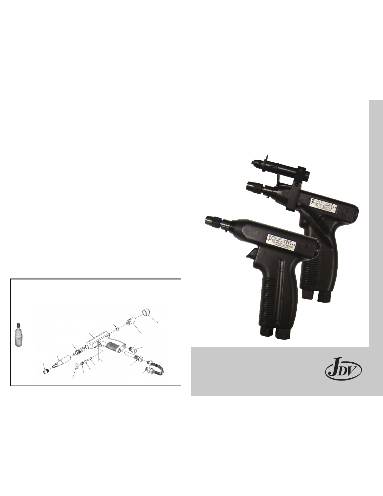
WG300
WG400
TRIGGERLESS
HERRAMIENTAS NEUMATICAS
PARA ENROLLADO DE ALAMBRE
PROCESO DE MANTENIMIENTO
MAINTENANCE PROCEDURE
COLLET NUT
A-10442
CLUTCH REGULAR ASSY
A-12145
BF CLUTCH ASSY
A-12160
CLUTCH HOUSING ASSY
A-12094
WG300 HOUSING ASSY
A-12113
WG400 HOUSING ASSY
12118
WASHER
A-12146
AIR MOTOR &
GEAR BOX ASSY
A-10714
END CAP
A-12141
TRIGGER
A-12136
BUSHING
A-12137
TRIGGER ROD
A-12139
TRIGGER PIN
A-12140
INTAKE VALVE ASSY
A-12126
WG300 HOSE ASSY
A-10738
WG400 HOSE ASSY
12738
MUFFLER ASSY
A-12119
O-RING
A-12138
A-15870
Rev 04/26/10
(Shown with optional WS650 Cut & Strip Tool Attachment)
All air tools require an air supply that is properly lubricated, regulated and ltered. Then tool will
give the operator long, trouble free life when the following procedures are observed:
Todas las herramientas requieren de aire que esta apropiadamente lubricado, ltrado y regulado en cuanto
a su presión. Así la herramienta dará al usuario una larga vida de uso sin problemas siguiendo los proced-
imientos siguientes:
1. The WG300 and WG400 are designed to operate at 90 to 100 psi (6.0-7.0 bar) input air
pressure. A regulator should be installed in the airline to insure proper input air pressure.
1. Las pistolas WG300 y WG400 están diseñadas para operar entre 90 a 100 psi (6.0-7.0 bar)
de presión de aire.
2. A lter should also be installed in the airline to remove dirt and dust particles that are
generally always present in unltered air system.
2. Un ltro es indispensable en la línea para detener partículas que puedan entrar a los
mecanismos internos de la herramienta. Estas partículas están presentes en sistemas sin
ltros.
3. The tool air supply should be moisture free.
3. El aire proporcionado a la herramienta deberá estar libre de agua y humedad.
4. The tool should be periodically lubricated dependent on the usage. If there is no automatic
lubricating device installed in the air line, the operator should pour approximately one (1)
teaspoon of high grade machine or spindle oil into the intake valve of the tool. If the tools is
used every day, this procedure should be done twice a week.
4. La herramienta tendrá que ser lubricada periódicamente dependiendo de su uso. Si no
existe un sistema que lubrique automáticamente en la línea de aire, el operador debreá
poner dentro de la pistola una cucharada de aciete para altas revoluciones. Si la
herramienta es utilizada todos los días, este proceso se deberá hacer dos veces por
semana.
JDV Products Inc. recommends the WAC100 Air Regulating System be installed in the air supply line.
The WAC100 is a precision oiler, lter and pressure regulating system in one compact unit. When installed in
the air line, it will insure that item 1, 2, and 3 above are in place and protecting the tool.
JDV recomienda el WAC100 Sistema de regulación de Aire en cada línea de aire. El WAC100 es un
lubricador de precisión, ltro y sistema regulador de presión en una unidad compacta. Al instalarse en la
línea de aire asegurara que los puntos 1, 2 y 3 sean cubiertos y protegerá debidamente a su herramienta.
A-15903
LUBRICANT (ACEITE)
Rock Drill Oil / ISO 32
WARRANTY WARNING:
Warranty VOID if A) tool’s taken apart, B) endcap is tampered with, C) if repairs are not done by a JDV Authorized Repair Facility, D) tool must be
used with proper air lter/regulator installed within 6 feet from tool, E) proper type oil/lubricant must be used (comes with tool, A-15903) and F)
air lines must be dry or have dryer unit installed. Contact JDV for closest Authorized Repair Facility.
GARANTÍA ATENCIÓN:
La garantía queda anulada si: A) herramientas de desmontar, B) tapón es alterado, C) si las reparaciones no son hechas por un JDV de
reparaciones autorizado de Fondo, D) la herramienta se debe utilizar con el ltro de aire / regulador instalado dentro de los 6 pies de la
herramienta, E) El aceite de tipo apropiado / lubricante debe ser utilizado (viene con la herramienta, A-15903) y F) las líneas de aire debe estar
seco o secador de unidad instalada. Contacto para JDV de reparaciones autorizado más cercano Fondo.
JDV Recommends using:
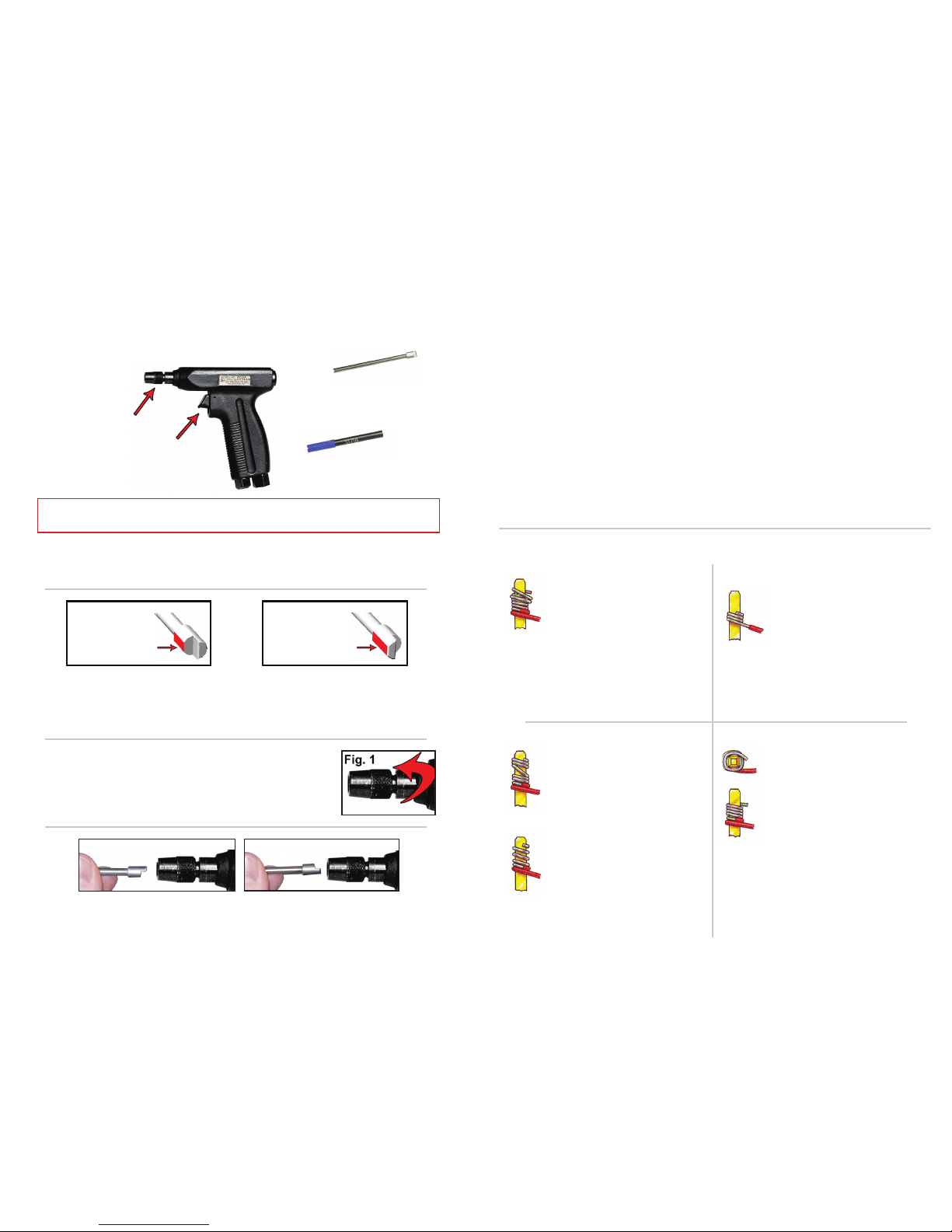
QUICK START GUIDE
Insertion of the Bit and Sleeve Into the Wire Wrapping Tool
3. Loosen the COLLET NUT. 2-3 threads showing.(Fig.1)
4. Insert the BIT into the COLLET NUT with the FLAT SURFACE facing DOWN.
3. Aoje la tuerca exponiendo de 2 a 3 hilos de la rosca.
(Figura 1)
4. Inserte la punta dentro adaptador de la pistola con la parte plana hacia abajo.
1. Familiarize yourself with the different components.
1. Familiarícese con los diferentes componentes.
2 7
SOME HINTS ON MAKING WRAPPED CONNECTIONS
Overwrap
Pigtail
Insufcient
Turns
Spiral Wrap
Open Wrap
Overwrap
Don’t press too hard. Pressing down too hard
on the tool during the wire wrapping operation
results in “overwrapping” in which one or more
turns of wire can slip over the preceding turns.
An anti-backforce device is helpful in preventing
overwrap.
Spiral or Open Wrap
Don’t remove the tool too quickly. Removal
of the wrapping tool before the wrap is com-
pleted can result in “spiral” or “open” wraps,
where one turn of wire is more than 0.005”
from another turn. “Pigtails”, where the nal
turn of wire is not completely wrapped, are
also caused by too rapid a removal of the
wrap tool.
Insufficient Turns
Push wire all the way into wire slot.
Improper feeding of the wire into the wire slot
of the bit results in insufcient turns of wire for
regular wraps or insufcient insulation turns for
modied wraps.
Pigtails
The particular wire wrapping bit and sleeve
depend upon the size (terminal diagonal) of
the terminal to be wrapped. If the terminal hole
diameter of the bit is improperly matched to the
terminal diagonal, defects ranging from loose
turns to “pigtails” can result.
Conexión Encimada
No presione muy fuerte. Al presionar muy fuerte
al hacer la operación de enrollado resulta una
conexión encimada. Un aditamento “anti-
backforce” es útil para prevenir conexiones
encimadas.
Vueltas Insuficientes
Empuje el cable hasta el fondo. Cargar el
cable en la punta inadecuadamente da como
resultado insucientes vueltas de cable para
enrollado regular y insucientes vueltas con
funda en enrollados modicaos.
Enrollado en Espiral o
Abierto
No retire la herramienta muy rápido. Al remover
la herramienta antes de que se complete el
enrollado resultara en “espiral” o “abierto”,
donde una vuelta de cable estará mas de
0.005 de otra. “Colitas” es cuando la ultima
vuelta no esta completamente enrollada, su
causa también es por retirar muy rápido la
pistola.
Colita
Seleccione la punta y manga correctas. La
particular punta y manga dependen del tamaño
de la terminal donde se hará la conexión. Si
el diámetro del agujero de la punta no es el
adecuado abran defectos como terminales ojas
y colitas que vienen siendo colitas o terminado
incorrecto.
GUIA BASICA DE INICIO
Inserción de la Punta y la Manga en la Pistola Manual
PISTOLA DE WIRE WRAP
COLLET NUT
MANGA PARA WIRE WRAP
TRIGGER
TUERCA PARA FIJAR
PUNTA Y MANGA
ALGUNOS CONSEJOS AL HACER CONECCIONES DE ENROLLADO
PUNTA PARA WIRE WRAP
WIRE WRAP GUN
GATILLO-ACTUADOR WIRE WRAP SLEEVE
WIRE WRAP BIT
TIPO A
SUPERFICIE PLANA
STYLE A
FLAT SURFACE
TIPO B
SUPERFICIE PLANA
STYLE B
FLAT SURFACE
Troubleshooting
If the trouble persists even though the bit and sleeve is inserted correctly, follow these steps to ensure that your
tolos are not damaged:
Remove the bit and sleeve from the wire wrap gun. Squeezing the trigger should provide a smooth motion. If the
gun does not operate smoothly or there is evidence of uneven wear on the bit, there may be internal damage
and the tool should be returned to JDV for evaluation.
The bit and/or sleeve may be bent or damaged. Try using a new JDV PRODUCTS bit and sleeve by following
the guide on page 2. For bit and sleeve selection, see pages 4-5.
With the bit and sleeve installed into the wire wrap gun, look into the tip of the sleeve. The indexing slot (where
the wire is inserted into the bit) should be at twelve-o-clock position. If this is not true, then the gun should be
returned to JDV for evaluation.
Localización de Problemas
Si esta teniendo problemas estando la punta y manga en posición correcta, siga los siguientes pasos para asegurar
que su herramienta no este dañada:
Remueva la punta y la manga de la pistola. Al apretar el gatillo deberá haber un movimiento suave. Si la pistola
no opera suavemente o existe evidencia de desgaste disparejo en la punta, es posible que haya daño interno en
la herramienta y deberá ser enviada a JDV para su evaluación.
La punta o la manga podrían estar dobladas o lastimadas. Pruebe utilizando una nueva punta de JDV Products
siguiendo los siete pasos en la pagina 2. Para seleccionar puntas y mangas vea la pagina 4-5.
Con la punta y la manga debidamente instaladas en la pistola de enrollado, mire la punta de la manga. El
agujero donde se monta el alambre en la punta deberá estar en la parte superior (posición de las 12:00 en
punto.) Si esto no es cierto, entonces la pistola tendrá que ser enviada a JDV para ser evaluada.
•
•
•
•
•
•
TIPO A
STYLE A STYLE B
TIPO B
2. Determine which style BIT you are using by identifying where the FLAT SURFACE is
located.
2. Determine que tipo de punta esta utilizando, identicando la parte plana de la misma.
WARRANTY WARNING:
Warranty VOID if a) tool’s taken apart, b) endcap is tampered with, c) if repairs are not done by a JDV Authorized Repair Facility, d) tool must be used with proper air lter/regulator
installed within 6 feet from tool, e) proper type oil/lubricant must be used (comes with tool, A-15903), f) air lines must be dry or have dryer unit installed and g) the air must de free of
moisture and dirt. Contact JDV for closest Authorized Repair Facility.

6 3
5. Rotate the BIT clockwise 180º to seat the BIT into the WIRE WRAP GUN. (Fig. 2)
When the BIT is seated properly, sqeezing the TRIGGER of the gun will make the BIT
spin.
6. Locate the KEY SLOT on the SLEEVE. (Fig. 3)
With the KEY SLOT pointing DOWN, slide the SLEEVE over the BIT and
engage with the pin inside the COLLET NUT. (Fig. 4)
7. Tighten the COLLET NUT while squeezing the TRIGGER. This will create a small
amount of clearance between the BIT, SLEEVE, and BIT DRIVER to prevent “locking”
occurs, the BIT will slow or jam the gun and produce grinding sounds. (Fig. 5)
5. Gire la punta hacia la derecha 180º para asentar la punta en su lugar en la pistola de
Enrollado. (Figura 2)
Cuando la punta es asentada apropiadamente, apretando el gatillo de la pistola hará
girar la punta.
6. Localice la ranura en la manga. ( Figura 3)
Con la ranura hacia abajo, deslice la manga sobre la punta y posicione el
pivote dentro de su posición. (Figura 4)
7. Apriete la tuerca mientras actúa el gatillo, para crear una separación entre la punta
y la manga, así como la guía de la pistola. Esto previene que se aprisione el me
canismo o que se produzcan ruidos con fricción. (Figura 5)
Wire Size Chart
A wire wrapped connection is made by coiling the wire around the sharp corners of a terminal under mechanical tension.
This method of connection was developed by Bell Telephone Laboratories, Western Electric Company.
Five Steps To Make A
Wire Wrap Connection
1
A “Regular” bit wraps the bare wire around the terminal. A “Modified” bit
wraps a portion of insulation around the terminal in addition to the bare wire.
This greatly increases the ability to withstand vibration.
A distinct advantage of wire wrapping is the ease with which a wire may
be removed from a terminal to correct errors or modify wiring. An unwrap
tool is slipped over the terminal, engaging the first turn of the connection.
Rotating the tool, the connection is removed in seconds, without damage to
the terminal.
2
3
4
5
Bare Wire Dia. AWG
(USA)
SWG
(GB)
In. mm
.0403 1.022 18
.040 1.016 19
.036 0.914 19 20
.032 0.813 20 21
.028 0.711 21 22
.0253 0.643 22
.024 0.61 23
.0226 0.574 23
.022 0.559 24
.0201 0.51 24
.020 0.508 25
.018 0.457 26
.0179 0.455 25
.0164 0.417 27
.0159 0.404 26
.0148 0.376 28
.0142 0.361 27
.0136 0.345 29
.0126 0.320 28
.0124 0.315 30
.0116 0.295 31
.0113 0.287 29
.0108 0.274 32
.0100 0.254 30 33
.0092 0.234 34
.0089 0.225 31
.0084 0.213 35
0.008 0.203 32
Regular Modified
Terminal Diagonal Chart
Un enrollado de punta“Regular” la parte de cable sin aislamiento se enrolla
en la terminal. Un enrollado de punta ”Modificado” tiene una porción de
aislamiento del cable enrollado en la terminal. Esto aumenta la habilidad de
soportar vibración.
Una ventaja distintiva del enrollado de cables es lo fácil que el cable puede
ser removido del terminal para corregir errores o modificar cableados. Una
herramienta de desenrollado es deslizada sobre la terminal agarrando la
primera envoltura o conexión. Rotando la herramienta, la conexión es
removida en segundos, sin ocasionar daños a la terminal.
Regular Modificado
Tabla de Calibres de Cable
Cinco Pasos para Hacer
una Conexión
Tabla para Identificar la Medida Diagonal de las Terminales
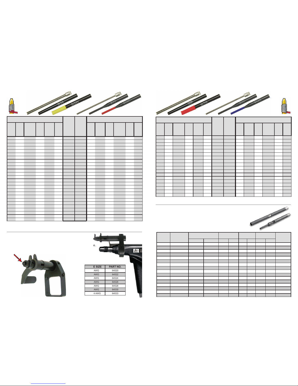
AWG (inches) BIT
PART
No.
SLEEVE
PART
No.
METRIC (mm)
Wire
Gauge
(AWG)
Max
Insu-
lation
Dia
Min/Max
Terminal
Diagonal
Term
Hole
Depth
Effective
Radius
Term
Hole
Dia
Term
Hole
Dia
Effective
Radius
Term
Hole
Depth
Min/Max
Terminal
Diagonal
Max
Insu-
lation
Dia
Wire
Gauge
(mm)
18 N/A .060/.073 1.000 .150 .075 BR18 S194 1.90 3.81 25.40 1.52/1.85 N/A 1.00
19 N/A .042/.073 1.000 .123 .075 BR19 S171 1.90 3.12 25.40 1.07/1.85 N/A 0.91
19-20 N/A .091/.122 1.000 .150 .125 BR1920L S212 3.17 3.81 25.40 2.31/3.09 N/A
.80-.91
20 N/A .091/.122 1.000 .150 .125 BR20L S212 3.17 3.81 25.40 2.31/3.09 N/A
.80-.91
20-22 N/A .042/0.73 1.000 .123 .075 BR20 S171 1.90 3.12 25.40 1.07/1.85 N/A
.65-.80
22 N/A .061/.085 1.000 .125 .086 BR22T S171 2.18 3.17 25.40 1.54/2.15 N/A 0.65
22 N/A .054/.073 0.750 .117 .075 BR22 S171 1.90 2.97 19.05 1.37/1.85 N/A 0.65
22-24 N/A .054/.073 1.000 .111 .075 BR224-1 S171 1.90 2.82 25.40 1.37/1.85 N/A
.50-.65
22-24 N/A .054/.073 0.807 .111 .075 BR224 S171 1.90 2.82 20.50 1.37/1.85 N/A
.50-.65
24 N/A .024/.043 1.000 .083 .044 BR2444* S125LN* 1.11 2.10 25.40 0.60/1.09 N/A 0.50
24 N/A .055/.074 1.500 .100 .075 BR24D S159 1.90 2.54 38.10 1.39/1.87 N/A 0.50
24 N/A .055/.074 0.750 .100 .075 BR24 S159 1.90 2.54 19.05 1.39/1.87 N/A 0.50
24-26 N/A .058/.073 0.750 .100 .075 BR2426 S159 1.90 2.54 19.05 1.47/1.85 N/A
.40-.50
24-26 N/A .054/.065 1.000 .098 .066 BR2466 S125LD 1.67 2.48 25.40 1.37/1.65 N/A
.40-.50
26 N/A .054/.073 1.000 .112 .075 BR16903 S159 1.90 2.84 25.40 1.37/1.85 N/A 0.40
26 N/A .023/.038 0.750 .068 .040 BR2639* S93LN* 1.02 1.72 19.05 0.58/0.96 N/A 0.40
26 N/A .058/.073 1.000 .100 .075 BR26 S159 1.90 2.54 25.40 1.47/1.85 N/A 0.40
30-32 N/A .034/.038 0.750 .064 .040 BR30* S93* 1.02 1.62 19.05 0.86/0.96 N/A
.20-.25
AWG (inches)
BIT
PART
No.
SLEEVE
PART
No.
METRIC (mm)
Wire
Gauge
(AWG)
Max
Insu-
lation
Dia.
Min/Max
Terminal
Diagonal
Term
Hole
Depth
Effective
Radius
Term
Hole
Dia
Term
Hole
Dia
Effective
Radius
Term
Hole
Depth
Min/Max
Terminal
Diagonal
Max
Insu-
lation
Dia
Wire
Gauge
(mm)
20 .058 .042/.073 1.000 .150 .075 BM20 S194LN 1.90 3.81 25.40 1.07/1.85 1.47 0.80
22 .054 .049/.074 1.000 .132 .075 BM22 S171 1.90 3.35 25.40 1.24/1.87 1.37 0.65
22-24 .050 .049/.074 1.250 .121 .075 BM224 S171 1.90 3.07 31.75 1.24/1.87 1.27
.50-.65
24 .046 .054/.073 1.750 .117 .075 BM24DD S171 1.90 2.97 44.50 1.37/1.87 1.17 0.50
24 .044 .024/.043 0.750 .098 .044 BM2444* S125LN* 1.11 2.48 19.05 0.60/1.09 1.11 0.50
24 .046 .054/.073 0.750 .118 .075 BM24 S171 1.90 2.99 19.05 1.07/1.85 1.17 0.50
24-26 .046 .054/.073 0.750 .118 .075 BM2426 S171 1.90 2.99 19.05 1.37/1.85 1.17
.40-.50
26 .031 .023/.038 0.750 .075 .040 BM2640* S93* 1.02 1.90 19.05 0.58/0.96 0.79 0.40
26 .046 .054/.073 1.000 .118 .075 BM26 S171 1.90 2.99 25.40 1.37/1.85 1.17 0.40
26 .044 .028/.044 0.750 .098 .044 BM2644* S125LN* 1.11 2.48 19.05 0.71/1.12 1.11 0.40
26 .042 .053/.068 1.000 .109 .069 BM2669 S159 1.75 2.77 25.40 1.34/1.72 1.04 0.40
26 .050 .053/.068 1.125 .118 .069 BM26D S171 1.75 2.99 28.50 1.34/1.72 1.27 0.40
28 .030 .031/.035 0.750 .066 .036 BM28* S93* 0.91 1.67 19.05 0.79/0.89 0.76 0.32
28 .030 .031/.035 1.125 .066 .036 BM28-1125* S93* 0.91 1.67 28.57 0.79/0.89 0.76 0.32
28 .030 .031/.035 1.250 .066 .036 BM28-1250* S93* 0.91 1.67 31.75 0.79/0.89 0.76 0.32
28 .034 .053/.068 1.000 .103 .070 BM2870 S159 1.78 2.61 25.40 1.35/1.72 0.86 0.32
28-29 .036 .033/.038 0.750 .091 .040 BM2840* S125* 1.02 2.31 19.05 0.83/0.96 0.91
.29-.32
30 .023 .030/.035 0.750 .061 .036 BM30SW* S93* .091 1.54 19.05 .099/1.06 0.58 0.25
30 .027 .031/.035 0.750 .064 .043 BM3043* S93* 1.09 1.62 19.05 0.79/0.89 0.69 0.25
30 .027 .031/.035 0.750 .064 .036 BM30* S93* 0.91 1.62 19.05 0.79/0.89 0.68 0.25
30 .027 .031/.035 1.125 .064 .036 BM30-1125* S93* 0.91 1.62 28.57 0.79/0.89 0.68 0.25
30 .023 .030/.035 0.750 .064 .036 BM30SI* S93* 0.91 1.62 19.05 0.76/0.89 0.58 0.25
30 .027 .060/.064 1.000 .106 .066 BM3066 S159 1.67 2.70 25.40 1.52/1.62 0.69 0.25
30 .027 .027/.030 0.750 .066 .031 BM3031* S93* 0.79 1.67 19.05 0.69/0.76 0.69 0.25
30-32 .027 .034/.038 0.750 .064 .040 BM3040* S93* 1.02 1.62 19.05 0.86/0.96 0.69
.20-.25
30-32 .029 .062/.065 1.000 .100 .067 BM3068 S125LD 1.70 2.54 25.40 1.57/1.65 0.74
.20-.25
All Bits & Sleeves are Fully Compatible with any Make or Model Wire Wrapping Tool
MODIFIED WRAP BITS & SLEEVES REGULAR WRAP BITS & SLEEVES
4 5
*These tools are recommended for .025” square terminals on 0.100 centers / 0.63 mm square on 2.54 mm centers.
PUNTAS Y MANGAS PARA WIRE WRAP ENROLLADO ACAMBRE
* Los modelos con asterisco son recomendados para terminales cuadradas de .025”
(0.63mm con distancias de 2.54mm entre el centro de una terminal y otra.)
Todas las Puntas y Mangas son Totalmente Compatibles con Cualquier Marca y Modelo de herramientas para Wire Wrap.
PUNTAS Y MANGAS PARA WIRE WRAP ENROLLADO ACAMBRE
Tipo
Modicado
Tipo
Regular
WIRE
SIZE
AWG
PART No.
BIT & SLEEVE
WIRE DIAMETER TERM. HOLE
DIAMETER
MIN. TERM.
SPACING “A” DIAMETER NUMBER OF
INSULATED
LOOPS
in. mm in. mm in. mm in. mm
22 79222 0.046-0.050 1.17-1.27 0.07 1.78 0.19 4.83 0.25 6.35 3/4
22 79223 0.050-0.054 1.27-1.37 0.07 1.78 0.19 4.83 0.25 6.35 3/4
22 79224 0.054-0.058 1.37-1.47 0.07 1.78 0.2 5.08 0.25 6.35 3/4
24 79241 0.028-0.032 0.71-0.81 0.07 1.78 0.16 4.06 0.21 5.33 3/4
24 79242 0.032-0.036 0.81-0.91 0.07 1.78 0.16 4.06 0.21 5.33 3/4
24 79243 0.036-0.040 0.91-1.02 0.07 1.78 0.16 4.06 0.21 5.33 3/4
24 79244 0.040-0.044 1.02-1.12 0.07 1.78 0.17 4.32 0.21 5.33 3/4
24 79245 0.044-0.048 1.12-1.22 0.07 1.78 0.17 4.32 0.21 5.33 3/4
26 79261 0.022-0.026 0.56-0.66 0.07 1.78 0.16 4.06 0.21 5.33 3/4
26 79262 0.026-0.030 0.66-0.76 0.07 1.78 0.16 4.06 0.21 5.33 3/4
26 79263 0.030-0.034 0.76-0.86 0.07 1.78 0.16 4.06 0.21 5.33 3/4
26 79266 0.025-0.029 0.64-0.74 0.043 1.09 0.112 2.85 0.146 3.71 3/4
26 79267 0.030-0.034 0.76-0.86 0.043 1.09 0.112 2.85 0.146 3.71 3/4
28 79281 0.022-0.025 0.56-0.64 0.038 0.97 0.102 2.59 0.13 3.3 3/4
30 79301 0.019-0.021 0.48-0.53 0.038 0.97 0.1 2.54 0.13 3.3 3/4
30 79302 0.019-0.022 0.48-0.55 0.038 0.97 0.1 2.54 0.13 3.3 3/4
Model WS650 works with all JDV pneumatic wire wrapping tools.
Order stripping blades separately from attachment to suit wire size.
MODEL WS650 - Cut 7 Strip Attachment
WIRE SIZE PART NO.
20 AWG 64520
22 AWG 64522
24 AWG 64524
26 AWG 64526
28 AWG 64528
30 AWG 64530
22-24 AWG 64533
Our Cut, Strip, and Wrap Bits are designed to cut the insulated copper wire to length, strip free
the necessary length of insulation, and wrap the correct number of wire loops around the
terminal pin.
CSW (Cut/Strip/Wrap) Bits
BLADE (SEE CHART)
This manual suits for next models
1
Table of contents
Other JDV Nail Gun manuals

Popular Nail Gun manuals by other brands

Metabo HPT
Metabo HPT NR 3675DD Instruction and safety manual

EXTOL PREMIUM
EXTOL PREMIUM 8894580 Translation of the original user manual

DeWalt
DeWalt XR Li-Ion DCN680D2 Original instructions

Performance Tool
Performance Tool M643 owner's manual

Hitachi
Hitachi VH650 - Fencing Nailer, Full Head instruction manual

Parkside
Parkside PET 25 B1 Operation and safety notes


