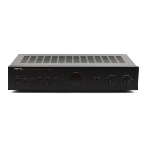
Jedia POWER 200A User manual

WWW.JEDIA.COM
POWER AMPLIFIER
POWER 200A
POWER 300A
POWER 600A
POWER 800A

AUTION AVIS
FEATURES
SAFETY INSTRUCTIONS
RONT PANEL CONTROLS
EAR PANEL CONTROLS
C
F
R
1
1
1
2
3
4
NSTALLATION (설치)
I
Clip / Lim
Signal
Power
Clip / Lim
Signal
Power
Ch 2
Ch 1
Temp
POWER
POWER 200A
Clip / Lim
Signal
Power
Clip / Lim
Signal
Power
Ch 2
Ch 1
Temp
POWER
POWER 300A
Clip / Lim
Signal
Power
Clip / Lim
Signal
Power
Ch 2
Ch 1
Temp
POWER
POWER 600A
Clip / Lim
Signal
Power
Clip / Lim
Signal
Power
Ch 2
Ch 1
Temp
POWER
POWER 800A
7
8
5~6
ONNECTIONS (연결 방법)
C
PECIFICATIONS
S
LOCK DIAGRAM
B

1
FEATURES 특 징
HIGH EFFICIENT
"π"type air flux design makes high efficient cooling.
Air flux from right front and side to left front and side.
PROTECTION
PEAK CLIPPING LIMITER CIRCUIT
POWER "ON" DELAY CIRCUIT (SOFT START)
BUILT IN BRIDGED MONO FUNCTION
5-WAY BINDING POST AND SPEAKON CONNECTOR
Over heating protection
Input signal will be cut-off automatically when temperature of heat-
sink is more than 100 C.
Speaker protection
Designed amplifier bum sound to be minimized when power on/off.
Short protection
When input signal is supplied under the out of work for speaker,
short protection will be operating automatically.
Over current protection
Built in over current protection to protect output transistor.
"π"형 공기 흐름은 기기 내부의 온도상승을 억제하며, 우수한 방열
효과를 나타냅니다.
우수한 방열 효과
방열판이 100 C를 넘게되면 자동적으로 입력신호가 끊기게 됩니다.
과열 방지회로
운용중 스피커 선로가 쇼트되면 쇼트 보호회로가 동작하여 앰프가
고장나지 않습니다.
스피커 선로 쇼트 보호회로
과출력시에 출력 트랜지스터를 보호하는 회로가 내장되어 있습니다.
과전류 보호회로
피크 클리핑 리미터 회로
파워"ON" 지연회로.(소프트 스타트회로)
브릿지 모노 기능내장
5-WAY 바인딩 포스트 및 스피콘 잭 채택
파워 스위치를 켜거나 끌때 생기는 붐 잡음을 최소화 하도록 설계되
어 있습니다.
스피커 보호회로
SAFETY INSTRUCTIONS
Read all safety instruction before operating the POWER A-Series amplifiers.
1. Install equipment as follow conditions.
The apparatus shall not be exposed to dripping or splashing and
no object filled with liquids, Such as vases, Shall be place on the
apparatus.
Install at the place, Not bending curved.
Do not install this apparatus in a confined space such as a book
case or similar unit.
Locate power amplifier away from heat source, Such as radiators
or other device that produce heat.
Do not drop objects or spill liquids into the inside of amplifier.
2. Keep in mind the following when connecting amplifier.
Connect the amplifier after reading of O/P manuals.
Connect each connection of amplifier perfectly, If not, It maybe
Caused hum, Damage, Electric shock in case of mis-connecting.
To prevent electric shock, Do not open top cover.
Connect the power cord with safety after check of AC power.
안 전 사 항
제품을 운용하기전에 모든 안전사항을 읽어 보십시오.
1. 이런 장소에 설치하여 주십시오.
진동이나 경사가 심하지 않고 바닥이 평평한 장소.
통풍이 잘되고 물기나 습기가 많지 않은 장소.
직사광선을 받지 않는 장소 또는 난방기구(발열체)에서 멀리 떨어진 장소.
인화성 물질(화학약품)이 없는 장소.
2. 설치시 이런점을 주의하십시오.
사용설명서 시스템 연결방법을 완전히 읽으신 후에 연결해 주십시오.
각종 연결선을 완전하게 연결해 주십시오.
(주전원 코드를 뽑은 상태에서 연결.)
불완전한 연결은 잡음, 제품의 손상 또는 안전사고의 원인이 됩니다.
전기적 충격 또는 감전사고의 위험이 있으므로 뚜껑을 열지 말아주십시오.
주 교류 전원 플러그를 연결하기 전에 사용전압을 확인하신 후 안전하게
연결하십시오.
제품을 수리시는 규정된 부품과 자격이 있는 사람이 수리를 하여야 함.
Amplifiers should be serviced by qualified service person.

1. LED INDICATOR
1. LED
FRONT PANEL CONTROLS
SIGNAL LED
SIGNAL LED light if the output signal exceeds 100mW.
POWER LED
POWER LED as operating light.
TEMP LED
overheating.
CLIP/LIM LED light with overdrive.
CLIP/LIM LED
When the temperature of the heatsink exceeds 100 degress,
the amplifier by muting the input/output signal thus preventing
2. CANNEL VOLUME
Control for the output level of channel 1,2.
switched on.
2~3 minutes before switching off.
For the internal fans continue to cool the unit otherwise the
amplifier maybe damaged.
NOTE:
1. To avoid loud switching noises, always switch on the power
amplifier in an amplifier system after all other units have been
2. At first turn the volume fully counterclockwise. Then wait approx
3. POWER SWITCH
Provides power to the unit.
CLIP/LIM LED
정격출력을 초과하여 일그러짐이 발생하면 LED가 켜지게 됩니다.
SIGNAL LED
POWER LED
출력 신호의 유무를 표시하여 주는 LED입니다.
앰프에 전기가 공급되고 있음을 알려주는 LED입니다.
TEMP LED
방열판의 온도가 100 C를 넘게 되면 LED가 켜집니다.
이때 입출력 신호는 뮤팅(차단) 되어 과열로 인해 발생할수 있는 사고를
방지할수 있습니다.
2. CHANNEL VOLUME
각 채널의 음량을 조절하는 볼륨입니다.
3. POWER SWITCH
※ 주의
기기에 전원을 공급하는 스위치 입니다.
켜십시오.
정도 기다린 후 방열판이 식으면 전원을 꺼주시기 바랍니다.
1. 앰프의 전원을 켤때는 주변 음향기기들을 먼저 켠 후에 앰프의 전원을
2. 앰프의 전원을 끌때는 볼륨을 반시계 방향으로 끝까지 돌리고, 23분
(전면기능)
2
1
2
3
Clip / Lim
Signal
Power
Clip / Lim
Signal
Power
Ch 2
Ch 1
Temp
POWER
POWER 800A

2. SIGNAL INPUT
퓨즈를 교체할 경우에는 지정된 부품을 사용하여야 하며,
파워PCB상의 FU1자리에 꽂아 주십시오.
REAR PANEL CONTROLS (후면기능)
1. AC POWER
전원 코드를 꽂기 전에 전원 스위치를 꺼주시기 바랍니다.
1. 교류 전원 공급
2. 입력단자
감전의 위험이 있으니 스피커 결선 작업을 하기전에 반드시
기기의 전원을 꺼주시기 바랍니다.
스피커 결선시에는 극성에 주의 하십시오.
스피커 결선시에는 전력 손실과 댐핑팩터의 감소를 최소화
하기 위하여 충분히 굵은 선을 최단거리로 결선 하십시오.
3. LIMITER SWITCHES
4. OUTPUT TERMINALS
3
Normal input level is 1.23V (+4dBm) 30K balanced with
channel 1,2 XLR and 1/4" phone jack input terminal, for
the
extension to another amplifier, connect link jack to another
amplifier input jack.
5. AMP MODE
바란스형 입력잭으로서 입력 감도는 +4dBm(1.23V) 30K 입니다.
5. 운용모드
스테레오
각 채널이 분리되어 운용할 경우에 사용되며 스피커 최소 부하는
4 입니다.
3. LIMITER SWITCHES
4. OUTPUT TERMINALS
WARNING : To prevent electric shock do not operate
the amplifier with any of the conductor portion of the
speaker wire exposed.
SPEAKER CABLING : Larger wire sizes and shorter
lengths minimize both loss of power and degradation
of damping factor.
Do not place speaker cables next to input wirring.
Please connect power plug after main power switch "off",
when fuse is blown-up please replace it, after disconnect
power cord. Fuse located in FU1 on power PCB.
When the audio signal drives the amp's output circuit beyond
it's power capability, it clips, flattening the peaks of the
waveform. The clip limiter detects this and quickly reduces the
gain to minimize the amount of overdrive. Limiting occurs only
during actual clipping. Each channel has its own clip limiter and
you can switch it on or off independently.
Turn the amplifier off befor touching the output connections.
출력 신호가 정격을 초과하게 되면 일그러짐이 발생하게 됩니다.
이때 리미터 스위치는 일그러짐이 발생하지 않는 레벨로 신호를
신속히 줄여주게 됩니다.
채널 1,2는 각각 독립적으로 동작하게 되며, 실제로 일그러짐이
발생했을때 CLIP/LIM LED가 켜지게 됩니다.
다이나믹 레인지는 +20dB 입니다.
MODEL VOLTAGE 220~240VAC (FU1)
T2AH 250V(55T)
T4AH 250V(55T)
T6.3AH 250V(55T)
T8AL 250V(S51)
120VAC (FU1)
T4AH 250V(55T)
T8AL 250V(S51)
T12AL 250V(65TL)
T15AL 250V(65TL)
DC FUSE (FU101,F2U01)
T4AH 250V(55F)
T5AH 250V(55F)
T6.3AH 250V(55F)
T8AL 250V(N51)
POWER 200A
POWER 300A
POWER 600A
POWER 800A
2
3
5
1
4
STEREO
Both channels operate separately : for stereo or 2-channel operation,
speaker impedance for each channel at least 4 .
브릿지 모노
채널1+ 콘넥터를 스피커+단자, 채널2+콘넥터를 스피커-단자와
연결하여 출력을 증강하기위한 방식으로 신호 입력을 채널1에만
공급합니다. 스피커 최소 부하는 8 입니다.
BRIDGE MONO
Both channels are connected as a bridge : for a speaker impedance
of at least 8 .

Clip / Lim
Signal
Power
Clip / Lim
Signal
Power
Ch 2
Ch 1
Temp
POWER
POWER 800A
(설치)

시스템 연결그림은 일반적인 설치 방법으로 다음사항을 주의 하십시오.
1. 스피커 라인 연결시 앰프의 전원 스위치를 꺼주십시오.
2. 스피커 결선은 결선도를 참고하여 주십시오.
3. 앰프는 2개의 모드(스테레오, 브릿지 모노)로 전환 시킬 수 있으며,
4. 잘못된 결선은 스피커에 치명적인 손상을 초래합니다.
앰프가 동작 중일때는 전환하지 마십시오.
스테레오 방식
결선 하십시오.
모드 스위치를 스테레오 쪽으로 전환하고 스피커 극성에 주의하여
Wiring the following instructions describe the most common
ways to install your amplifier into a sound system.
1. First, turn off power switch befor connection.
2. Refer to wirning diagram for speaker connection.
(stereo, bridge-mono)
3. L series amplifier maybe operated in one of two modes
4. JEDIA assumes no liability for damaged loads resulting from
careless amplifier use or deliberate over powering.
How to connect stereo(2-CHANNEL) MODE
connect the output wiring as shown.
To put the amplifier into stereo mode, first turn the amplifier off,
then slide the stereo-mono switch toward the left, and properly
CONNECTIONS
5
PIN1
PIN1
PIN1
PIN1
CH-1
CH-2
METHOD 1
CH-1
CH-2
CH-1
CH-2
METHOD 2
NO USE
TRIPAC series or
STAGE PRO MIXER
PROFESSIONAL AUDIO MIXER 8.4.4.2
TRIPAC

CONNECTIONS
6
How to connect bridge mono mode.
Bridged mono is intended for driving loads with a total impedance
of 8ohms or greater to put the amplifier in bridged mono mode,
turn the amplifier off and slide the stereo-mono switch toward
the right.
Both outputs receive the signal from CH"1" with the output of
CH"2".
Keep the level control of CH"2" turned completely down.
(counterclockwise)
브릿지 모노 방식
모드 스위치를 브릿지 모노에 위치 시키고 스피커 극성에 주의하여 결선
하여 주십시오. 채널 2의 볼륨은 반시계 방향으로 완전히 돌리고, 채널 1
볼륨으로 적당한 레벨로 설정하여 운용하십시오.
TRIPAC series or
STAGE PRO MIXER
PROFESSIONAL AUDIO MIXER 8.4.4.2
TRIPAC
NOT USE

7
SPECIFIATIONS (규격 및 성능)
8 ohms stereo 75W
100W
200W
124W
189W
364W
198W
306W
600W
269W
412W
800W
72W
95W
188W
118W
181W
345W
189W
296W
566W
260W
392W
750W
4 ohms stereo
8 ohms bridge
8 ohms stereo
4 ohms stereo
8 ohms bridge
Power Consumtion
9.5/20.9 10.5/23.2 11.5/25.4 12.5/27.6
408W 667W 1047W 1398W
3.1A/1.55A 4.9A/2.45A 6.28A/3.14A
1.88A/0.94A
7.24A/3.62A 11.1A/5.57A 14.7A/7.33A
4.34A/2.17A
Power supply
Cross talk at 8 ohms load(A weighted)
Slew Rate
Damping Factor
Signal-to Noise Ratio
A weighted, RMS, to rated output level
IMD-SAMPLE
60Hz, 7KHz, RMS output power
Input Sensitivity at 4 ohms rated output power
Voltage Gain refrence 1KHz
Frequency Respones
1/8 Power Curr. Draw 120V/220V~240V/4
Max Curr. Draw 120V/220V~240V/4
Weight(Kg/Ibs)
Dimensions
Specifications and design subject to change without notice for improvements.
(내용상의 규격 및 특징은 제품의 성능 향상을 위하여 사전 예고 없이 변경될 수 있습니다.)
NOTE

CH-1
INPUT
LINK
E.B
TEMP
CH-2
CH-1
CH-1 SIG
CH-2 SIG
CH-2 AMP
15V
CH-1 AMP
FU 101
FU 201
CH-1 PWR
CH-2 PWR
AC
FUSE
FU1
CH-2
INPUT
POWER
SWITCH
POWER
TRANSFORMER
CH-2 CLIP/LIM
LEVEL
LEVEL
CH-1 CLIP/LIM
STEREO
BRIDGE
MONO
LOCK DIAGRAM (블럭도)


POWER AMPLIFIER
POWER 200A, 300A, 600A, 800A
OPERATING INSTRUCTIONS
4M-OP202110
This manual suits for next models
3
Table of contents
Other Jedia Amplifier manuals

Jedia
Jedia JMA-300A User manual

Jedia
Jedia JPA-1120EM User manual
Jedia
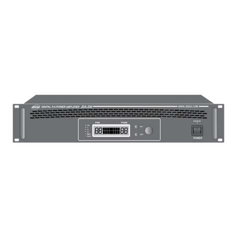
Jedia JDA-250 User manual
Jedia
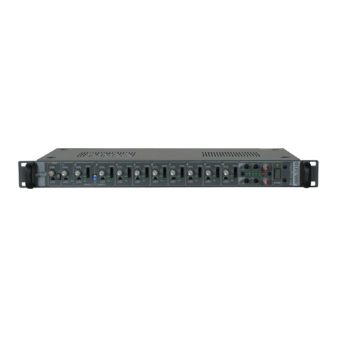
Jedia JMA-1410 User manual
Jedia
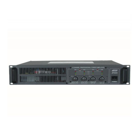
Jedia JFX-425 User manual
Jedia
Jedia JPA-1060 User manual
Jedia
Jedia MMA-400 Series User manual

Jedia
Jedia JPA-1120B User manual
Jedia
Jedia MOBILE 35 User manual
Jedia
Jedia JPA-060CP User manual
