Jedia EFFECT PRO 8224 User manual

L
INSERT
R
MONO
GAIN -30dB GAIN
-15
0
–40
-20
+10
-50
dB
-20
-45
-30
12KHz
HF
100Hz
12KHz
HF
15 15
U
15 15
U
15
U
15
350
MF
3.5K
1K
7K
150
15 15
U
80Hz
LF
U
15 15
80Hz
LF
U
15 15
00
PAN BAL
SGN
CLIP
PFL
SGN
CLIP
PFL
PAD
-10
0
+20 -20
dB
+10 -15
+5
2.5KHz
MF
LR
LR
00
R
MONO
GAIN
12KHz
HF
15 15
U
15 15
U
80Hz
LF
U
15 15
0
BAL
SGN
CLIP
PFL
11/12
-10
0
+20 -20
dB
+10 -15
+5
2.5KHz
MF
LR
0
9
6
3
0
3
6
9
12
Ð
12
+
9
6
3
0
3
6
9
12
Ð
12
+
9
6
3
0
3
6
9
12
Ð
12
+
RIGHT
300Hz
120Hz
50Hz 2KHz 5KHz 12KHz
AUX2
SEND
PRE
AUX2
0
L.R
OUT
10
0
INPUT
TRIM
+9
LEFT RIGHT
+6
+3
0
dB
-
30
-
24
-
18
-
15
-
12
-
9
-
6
-
3
10
0
AUX1
SEND
10
0
STEREO
RTN/TAPE2
10
0
STEREO
RTN/T
APE1
LINE
INSERT
GAIN -30dB
-15
-40
-20
+10
-50
dB
-20
-45
-30
12KHz
HF
100Hz
15 15
U
15 15
350
MF
3.5K
1K
7K
150
80Hz
LF
U
15 15
0
PAN
SGN
CLIP
PFL
PAD
LR
0
MIC
LINE
INSERT
GAIN -30dB
-15
-40
-20
+10
-50
dB
-20
-45
-30
12KHz
HF
100Hz
15 15
U
15 15
350
MF
3.5K
1K
7K
150
80Hz
LF
U
15 15
0
PAN
SGN
CLIP
PFL
PAD
LR
0
5
MIC
LINE
INSERT
GAIN -30dB
-15
-40
-20
+10
-50
dB
-20
-45
-30
12KHz
HF
100Hz
15 15
U
15 15
350
MF
3.5K
1K
7K
150
80Hz
LF
U
15 15
0
PAN
SGN
CLIP
PAD
LR
0
4
MIC
LINE
INSERT
GAIN -30dB
-15
-40
-20
+10
-50
dB
-20
-45
-30
12KHz
HF
100Hz
15 15
U
15 15
350
MF
3.5K
1K
7K
150
80Hz
LF
U
15 15
0
PAN
SGN
PAD
LR
0
LINE
INSERT
GAIN -30dB
-15
-40
-20
+10
-50
dB
-20
-45
-30
12KHz
HF
100Hz
15 15
U
15 15
350
MF
3.5K
1K
7K
150
80Hz
LF
U
15 15
0
PAN
PAD
0
GAIN -30dB
-15
-40
-20
+10
-50
dB
-20
-45
Ð30
12KHz
HF
100Hz
15 15
U
15 15
350
MF
3.5K
1K
7K
150
80Hz
LF
U
15 15
U
PAD
U
0
Ð50
Ð20
Ð45
12KHz
15 15
U
15 15
350
MF
3.5K
1K
7K
150
80Hz
LF
U
15 15
AUX1
U
0
9/10
8
7
6
LEFT RIGHT SEND
AUX2
AUX1
AUX2
AUX1
AUX2
AUX1
AUX2
AUX1
AUX2
AUX1
AUX2
AUX1
AUX2
AUX1
AUX2
AUX1
AUX2
AUX1
U
U
U
U
U
U
U
dB
VU METER
800Hz
+
+
+
Ð
Ð
Ð
+
+
+
+
+
+
Ð
Ð
Ð
Ð
Ð
Ð
-10
-10
0
-10
0
-10
0
-10
0
-10
0
-10
0
10
+dB
10
+dB
5
U
10
+dB
5
U
5
10
10
+dB
5
U
5
10
20
30
10
+dB
5
U
5
10
20
30
50
O
O
dB
10
+dB
5
10
+dB
5
U
5
10
20
UU
U
U
U
U
U
U
U
U
U
U
U
U
U
U
U
U
U
U
U
U
U
U
U
U
U
U
U
U
CLIP
LINE INUT,MIX OUTPUT
EQ INPUT, EQ OUTPUT
EXT AMP INPUT
SRT
S(GND)
T(+)
R(
-
)
DSP
DSP
DSP
DSP
DSP
DSP
DSP
DSP
DSP
DSP
DIGITAL SIGNAL
PROCESSOR
EFFECT PRO
8224
MIXING CONSOLE
21
3
21
3
21
3
4M-OP298090
INSTRUCTIONS
MIXING CONSOLE
EFFECT PRO 8224
OPERATING

1
SAFETY INSTRUCTIONS
Read all safety instruction before operating the 4Bus console.
1. INSTALL EQUIPMENT AS FOLLOW CONDITIONS
Install at the place, not bending curved.
Do not install this apparatus in a confined space such as a book case or similar unit.
The apparatus shall not be exposed to dripping or splashing and no object filled with liquids,
such as vases, shall be place on the apparatus.
Locate mixers away from heat source, such as radiators or other device that produce heat.
Do not drop objects or spill liquids into the inside of mixers.
2. KEEP IN MIND THE FOLLOWING WHEN CONNECTING AMPLIFIER
Connect the mixers after reading of O/P manuals.
Connect each connection of mixersperfectly, if not, it maybe Caused hum, damage, electric shock
in case of mis-connecting.
To prevent electric shock, do not open top cover.
Connect the power cord with safety after check of AC power.
Mixers should be serviced by qualified service person.
WORNING: To reduce the risk for fire or electric shock, do not expoes this appliance to rain or moisture.

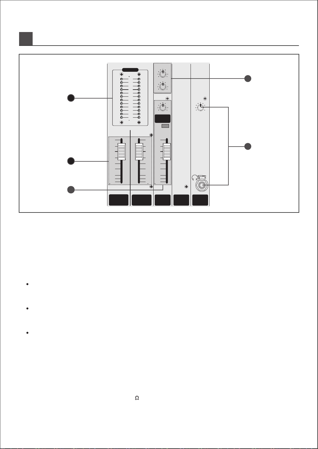
PANEL LAYOUT AND FEATURES
2
1. NOISE DETECTOR POWER INDICATOR
When ambient noise detector(JND-011) is connected to pickup input(XRL jack) of rear panel, noise
detector power LED is turned on.
Then, you can confirm that power supply to ambient noise detector is normal.
5
MIC
LINE
INSERT
4
MIC
LINE
INSERT
3
MIC
LINE
INSERT
2
MIC
LINE
INSERT
1
MIC
LINE
INSERT
GAIN –30dB
–15
–20
+10
–50
dB
–20
–45
–30
PAD
–10
0
–40
MONO
GAIN –30dB GAIN
–40
PAD
–10
0
+5
MONO
GAIN
–10
0
+5
GAIN –30dB
–40
PAD
GAIN –30dB
–40
PAD
GAIN –30dB
–40
PAD
GAIN –30dB
–40
PAD
GAIN –30dB
–40
PAD
GAIN –30dB
–40
PAD
–10–10–10–10–10–10–10
8
9/10
MIC
LINE
INSERT
11/12
7
MIC
LINE
INSERT
6
MIC
LINE
INSERT
L
R
L
R
L
R
L
R
–20
+10
–50
dB
–20
+20 –20
dB
+20 –20
dB
–20
+10
–50
dB
–20
–20
+10
–50
dB
–20
–20
+10
–50
dB
–20
–20
+10
–50
dB
–20
–20
+10
–50
dB
–20
–20
+10
–50
dB
–20
–15
0
–45
–30
+10 –15
–15
–45
–30
–15
–45
–30
–15
–45
–30
–15
–45
–30
–15
–45
–30
–15
–45
–30
000000
+10 –15
12KHz
HF
100Hz
12KHz
HF
UU
12KHz
HF
U
12KHz
HF
100Hz
U
12KHz
HF
100Hz
U
12KHz
HF
100Hz
U
12KHz
HF
100Hz
U
12KHz
HF
100Hz
U
12KHz
HF
100Hz
U
12KHz
HF
100Hz
U
15 15
1K
15 15
1K
15 15
1K
15 15
1K
15 15
1K
15 15
1K
15 15
1K
15 15
1K
350
MF
3.5K
80Hz
LF
350
MF
3.5K
7K
150
80Hz
LF
350
MF
3.5K
150
80Hz
LF
350
MF
3.5K
7K
150
15 15
350
MF
3.5K
7K
150
80Hz
LF
350
MF
3.5K
7K
150
7K
150
7K
UU
15 15
80Hz
LF
U
15 15
15 15
80Hz
LF
U
15 15
U
15 15
15 15
80Hz
LF
U
15 15
15 15
U
15 15
15 15
U
15 15
15 15
U
15 15
UUUUU
15 15
15
U
15
350
MF
3.5K
7K
150
15 15
U
80Hz
LF
U
15 15
80Hz
LF
U
15 15
2.5KHz
MF
15 15
15 15
U
80Hz
LF
U
15 15
2.5KHz
MF
350
MF
3.5K
7K
150
00
PAN BAL
LRLR
00
0
BAL
LR
0
0
PAN
LR
0
0
PAN
LR
0
0
PAN
LR
0
0
PAN
LR
0
0
PAN
LR
0
U
0
PAN
LR
U
0
AUX
2
U
0
AUX
1
PAN
LR
U
0
AUX
2
AUX
1
AUX
2
AUX
1
AUX
2
AUX
1
AUX
2
AUX
1
AUX
2
AUX
1
AUX
2
AUX
1
AUX
2
AUX
1
AUX
2
AUX
1
AUX
2
AUX
1
U U
U
U
U
U
U
U
U
U
U
U
U
U
U
U
U
U
U
U
U
U
U
U
U
U
DSPDSP
DSPDSPDSPDSPDSPDSPDSPDSP
SGN
CLIP
PFL
SGN
CLIP
PFL
SGN
CLIP
PFL
11/12
SGN
CLIP
PFL
SGN
CLIP
PFL
SGN
CLIP
PFL
SGN
CLIP
PFL
SGN
CLIP
PFL
SGN
CLIP
PFL
SGN
CLIP
PFL
9/10
87654321
9
6
3
0
3
6
9
12
–
12
+
9
6
3
0
3
6
9
12
–
12
+
LEFT
POWER SECTION
PHANTOM
+48V ON
IN
OUT(REC)
AUX
SEND
STEREO
RETURN
TAPE
1
2
R
L
LEFT
RIGHT
+
+
+
–
–
–
+
+
+
–
–
–
R
L
EQ MIX OUT
LINE . EQ INUT,
MIX OUTPUT
CHANNEL
INSERT AUX1,2 OUTPUT STEREO RETURN
INPUT
SRT
S(GND)
T(+)
R(
-
)
SRTSRTSRT
S
T(+)
R(GND) R(RIGHT)
S(GND)
T(LEFT)
S(GND)
T(IN)
R(OUT)
12 312
3
L
R
MIC INPUT EQMIX OUT
MIX.OUT EQ.IN
9
6
3
0
3
6
9
12
–
12
+
9
6
3
0
3
6
9
12
–
12
+
300Hz120Hz50Hz 2KHz 5KHz 12KHz
800Hz
+
+
+
+
+
+
–
–
–
–
–
–
+9
LEFT RIGHT
+6
+3
0
dB
-
30
-
24
-
18
-
15
-
12
-
9
-
6
-
3
dB
VU METER
10
0
PHONES
U
200
GLR
LR
8
9/10 11/12 RIGHT SEND
7654321
PHONES
LEFT DE
10
+dB
5
U
5
10
20
30
50
OO
dB
10
+dB
5
U
5
10
20
30
50
OO
dB
10
+dB
5
U
5
10
20
30
50
OO
dB
10
+dB
5
U
5
10
20
30
50
OO
dB
LEFT
10
+dB
5
U
5
10
20
30
50
OO
dB
10
+dB
5
U
5
10
20
30
50
OO
dB
10
+dB
5
U
5
10
20
30
50
OO
dB
10
+dB
5
U
5
10
20
30
50
OO
dB
10
+dB
5
U
5
10
20
30
50
OO
dB
10
+dB
5
U
5
10
20
30
50
OO
dB
10
+dB
5
U
5
10
20
30
50
OO
dB
10
+dB
5
U
5
10
20
30
50
OO
dB
10
+dB
5
U
5
10
20
30
50
OO
dB
AUX 2
SEND
PRE
10
0
AUX
1
SEND
10
0
STEREO
RTN/TAPE
2
10
0
STEREO
RTN/TAPE
1
RIGHT SEND
U
U
U
EFFECT PRO 8224
MIXING CONSOLE
RIGHT
3
2 1
3
2 1
3
3
3
3
3
2 1
3
2 1
2 1
2 1
2 1
2 1
21
21
FEATURES
EFFECT PRO 8224 have been designed based on efficient & high quality sound and reliability for
professional players requirements.
THE MIXER
Mono(8ch) stereo(2ch) input.
Mix(master)L/R, AUX1/2, Recording output L/R.
Phabtom power for condenser microphone.
3 band EQfor live sound conrol per channel.
High pass filter per input channel(mono).
Output 19" rack mount for international standard.
Available to insert mono input channels.
PFL solo for all channels.

ADJUSTMENT PROCEDURE
3
Adjustment Procedure
1. Select the following as the supplied signal sources at each channel.
Gain control, each function, control fader, Mixer(master) fader etc have an effect on master output,
so you are kindly requested volume control at "u" position to balance gain control on operating
EAFFECT PRO 8442, it is difficult to control volume if high or low for volume level.
If channel will be used for microphone input.
→ Don't depress the pad switch.
2. Adjust the channel as the following.
Turn the gain control all the way counterclockwise.
Turn the AUX sends (AUX 1~4) control all the way counter-clockwise.
Don't depress / 100Hz switch.
Turn the EQ control to the center.
Turn the PAN pot to left or right.
Place fader "u" position.
Depress PFL switch.
Plug in headphone connector into headphone jack.
1. Minimize at feedback by adjustment of fixed direction and location speaker.
2. Adjust input fader according to procedure so as not to make howling.
3. Adjust mid EQ for reducing howling.
4. After marking of setting up for fader. And return to initial setting.
3. Adjust as the following after supply of level signal.
If you turn the gain controller to the clockwise slowly, input signals is appeared at the L/R Mix meter
(Adjust the signal level to 0dB, then the signal LED will be lighten)
If you want to check input signal, turn headphone controller to clockwise slowly.
If you need better sound adjustment, adjust gain control again after EQ setting.
Depress PFL switch again after the above procedure.
4. Adjust Mix(master) out section as below
Adjust meter indicator at 0dB via L/R fader(0dB=output +4dB/1.23V RMS).
You can check volume and level for sound via headphone.
For mixing output control, adjust gain control of input module at 0dB after setting of GRAPHIC EQ.
5. Select as the following, if meed for mic input
Depressing the switch of/100Hz, rumble of low frequency for vocal and plosive of microphone will be closed.
Improvement ofsound quality by GRAPHIC EQ
6. Adjust the other input strip as the above.
If microphone will be used for phantom power.
→ Connect Mic connector into the jack before depressing the phantom switch.
If channel will be used for line level like a key board, DI BOX.
→ Depress PAD switch or turn gain controller to counterclockwise to be proper setting.
IMPORTANT LEVEL SETTING
It is necessary to minimize howling, using the mic.
For the better sound without howling, we recommend using of JFS-142 to minimize howling due to
bandwidth of octave of MID peaking curve.
HOW TO MINIMIZE AT HOWLING

LAYOUT AND FUNCTION OF INPUT CHANNELS
4
1. MIC INPUT
The channel microphone(1) is a standard 3-pin female(XRL) connector. Pin one is
ground, pin two is signal high(+), pin three is signal low(-), as per the afreed-upon
international standard. When pushing on phantom switch, +48V will be fed to pin
2, 3 of mic connector which is impossible to use unbalanced microphone.
2. LINE INPUT
The channel line input(2) is a TRS (tip-ring-sleeve) balanced 1/4" phone jack, with
ground wired to the sleeve, signal high(+) to the tip and signal low(-) to the ring,
usually, signal can be supplied from keyboard, sampler, pre-amp and can be effective
for noise and hum reduction, Input variable range is -20dB ~ +10dB according to
position of gain control in case input connecting, tip is "+", ring/sleeve is "ground".
3. INSERT
As a route of channel signal change, the tip carries the signal back of the channel
(the return), and the ring carries signal out to the channel(the send). The channel
jack allows you to insert external processing equipment(such as compressor, gate)
into main signal path of the input channel strip. Insert point is located the front of
HPF(100Hz), EQ, Gain controller you can adjust EQ or HPF to minimize hum.
4. PAD SWITCH
Pushing pad switch for support gain volume, input sensitivity of min/line will be
reduced at 30dB Gain control range is limited with "0" marking.
5. GAIN CONTROL
This is for control of mic/line input sensitivity, this control acts as a sensitivity control
covering a 30dB range.
Channel signal level increase as the control is turned clockwise.
Input sensitivity of mic/line is -50dB ~ -20dB(for PAD -20dB ~ +10dB).
Warning : To protect speakers, do not insert condenser mic or pull it out phantom
power on and you can use trans output balanced dynamic mic under phantom
power on.
※
Warning :
It is necessary to adjust gain control for headroom and noise reduction.
If it clipped indicator red, you have to adjust gain control to the counter clockwise
or depress PAD switch.
1
MIC
LINE
INSERT
GAIN –30dB
–15
–40
–20
+10
–50
dB
–20
–45
–30
12KHz
HF
100Hz
15 15
U
15 15
350
MF
3.5K
1K
7K
150
80Hz
LF
U
15 15
AUX
2
U
0
AUX
1
PAN
SGN
CLIP
PFL
1
PAD
LR
U
0
1
U
–10
0
10
+dB
5
U
5
10
20
30
50
OO
dB
U
DSP
21
3
1
2
3
4
5
8
10
12
11
13
9
6
77
MONO STRIP
6. 100Hz SWITCH
Locating at the rear of head amp, pressing this switch inserts a 12dB per octave
100Hz (high pass filter) in the signal path immediately after the input amplifier, this
is particularly useful on line vocal, and its use is strongly recommended, even on
male 2 vocals, it can be used for filtering out low frequency hum.

LAYOUT AND FUNCTION OF INPUT CHANNELS
5
7. EQUALIZER(HF, MF, LF) SECTION
8. DSP or DE SWITCH
This switch is located at the rear of AUX1 volume control pressing switch, signal will be supplied to
DSP(Digital signal processing).
Turn volume control of AUX1 at "u" mark as the feature.
0
AUX 1
U
U
DSP
HI FREQ EQ CONTROL
9. AUX SEND (1~2)
Two AUX buses send your signal to internal or external effects, or to a foldback mix-on-stage AUX1 is a
post-fader-send, which can be switched between the internal DSP and an external feed.
AUX2 can be post-fader, pre-fader for effect.
10.PAN POT
The pan pot determines the position of the signal within stereo mix image or maybe used to route the channel
to particular out mix rotation fully counter clockwise feeds the signal solely to the right.
12.PFL SWITCH
Pre fader listen let you cue up music on headphone without interrupting the main mix.
CLIP LED is "turn on" and pressing PFL switch, signal is fed to headphone.
13.CHANNEL FADER
This 60mm fader determines the proportion of the channel in the mix and provides a clear visual indication of
channel level with "dB" printed normal operating position is at the "u" mark providing 10dB of gain above that
point if required.
You had better to use proposition of channel fader at "u".
11.CLIP, SIGNAL INDICATOR
LED on the channel illuminates as a clip indicator. To warn when an excessively high signal level is present in
the channel. The CLIP LED will illuminate approximately 5dB before clipping and therefore give warning of a
possible overload even if the peaks are removed by external equipment plugged into the insert. Signal green
LED is £-60dB PFL (pre fader). When the PFL switch is section illuminates to warn that the headphones and
the meters are now responding to the PFL/AFL selection. This is a useful way of listening to any required input
signal without interrupting the main mix, for making adjustment or tracing problem.
This is a fixed 12KHz shelving EQ with ±¾15dB of equalization available.
Shelving EQ works on a very broad range of frequencies and consequently are very musical.
In a 12KHz shelf like this section, that means that all the upper harmonic of sound are raised evenly, basically
keeping their original musical relationship to each other.
A high frequencies shelving EQ is great for putting shimmer into acoustic guitar and piano tracks and sizzle
into vocals.
MID FREQ EQ CONTROLS
The mid EQ controls is a variable EQ with ±¾15dB and variable range is 150Hz~7KHz this peaking EQ will
add or remove or make soft voice and clearance.
LOW FREQ EQ CONTROLS
The low EQ is a fired 80Hz shelving EQ with ±15dB of equalization available it is fine bass control a
LOW-FREQ shelving EQ will add or remove bass in a smooth, musical fashion good for working on bass drum
and guitar, fattening up a piano or contouring an entire mix.
※

LAYOUT AND FUNCTION OF INPUT CHANNELS
6
14.STEREO INPUT
Stereo inputs have two type of jacks, one is left and right unbalanced RCA jack and
the other is left and right balanced 1/4" phone jack with tip "+", ring "-", sleeve "ground".
15.MONO SWITCH
Pressing this switch, it will be changed into from stereo signal to mono.
In case of same level input, it will be increased at 6dB.
16.GAIN CONTROL
You can adjust input sensitivity of stereo balanced and unbalanced in detail through
gain control.
Variable range is 40dB and stereo input sensitivity range is -20dB ~ +20dB.
It is necessary to adjust gain control for the better noise and headroom.
17.EQUALIZER (HF, MF, LF)
The EQ is consists of three sections the upper control provides H.F 12KHz(treble).
Boost and cut of ±15dB. Each stereo input is provided with 3 band EQ section.
HF and LF 80Hz are shelving type and MF 2.5KHz is peaking type.
19.AUX SEND (1~2)
Two AUX buses send your signal to internal or external effects, or to a foldback
mix-on-stage. AUX1 is a post-fader send, which can be switched between the internal
DSP and an external feed. AUX2 can be post-fader, pre-fader for effect.
20.BALANCE
BAL control sets the relative mix out of left and right level, in the center position.
It's gain unity. Turning the control fully clockwise increases the right, full counter
clockwise rotation is the left.
22.PFL SWITCH
Pre fader listen let you cue up music on headphone without interrupting the main mix.
CLIP LED is "turn on" and pressing PFL switch, signal is fed to headphone.
23.CHANNEL FADER
This bottom fader determines the proportion of the channel in the mix and provides a
clear visual indication of channel level with "dB" printed normal operating position is
at the "u" mark providing 10dB of gain above that point if required.
You had better to use proposition of channel fader at "u".
21.CLIP, SIGNAL INDICATOR
LED on the channel serves as a clip indicator. To warn when an excessively high
signal level is present in the channel. The CLIP LED will illuminates approximately
5dB before clipping and therefore give warning of a possible overload even if the
peaks are removed by external equipment plugged into the insert. Signal green
LED is -60dB PFL (pre fader). When the PFL switch is pressed, the pre fader signal
is fed to the headphone, where it replaces the selected source, the PFL/AFL LED
on the master section illuminates to warn that the headphones and the meters are
now responding to the PFL/AFL selection. This is a useful way of listening to any
required input signal without interrupting the main mix, for making adjustment or
tracing problem.
18.DSP or DE SWITCH
Warning : To protect speakers, do not insert condenser mic or pull it out phantom
power on and you can use trans output balanced dynamic mic under phantom
power on.
※
※
※
STEREO STRIP
9/10
L
R
L
R
MONO
GAIN
12KHz
HF
15 15
U
15 15
U
80Hz
LF
U
15 15
0
BAL
SGN
CLIP
PFL
Ð10
0
+20 Ð20
dB
+10 Ð15
+5
2.5KHz
MF
L R
0
9/10
AUX
2
AUX
1
10
+dB
5
U
5
10
20
30
50
OO
dB
U
U
U
DSP
19
15
16
14
18
22
21
23
17
20
This switch is located at the rear of AUX1 volume control pressing
switch, signal will be supplied to DSP(Digital signal processing).
Turn volume control of AUX1 at "u" mark as the feature.
0
AUX 1
U
U
DSP
※
OUTPUT CHANNEL, MONITOR, DSP&DE
7
1. NOISE DETECTOR POWER INDICATOR
When ambient noise detector(JND-011) is connected to pickup input(XRL jack) of rear panel, noise
detector power LED is turned on.
Then, you can confirm that power supply to ambient noise detector is normal.
24.LEVEL METERING
Mix output and monitor level are illuminated by LED meter with the max +9dB, min -30dB.
LED meter has a three colors 12steps with pink color and is operated as a peak to peak meter. (ovu=+4dB)
27.STEREO RETURN/TAPE LEVEL CONTROLS
STEREO RTN/TAPE is provided to main mix L/R from RCA pin jack, 2-track return and phone jack stereo return
input. Two track return is for control of L/R simultaneously.
28.PHONES
For the initial setting of mixer, it can be monitored each channel through the headphone for adjusting of sound
quality and recommended impedance is 200 over.
Headphone jack ; TIP : LEFT, RING : RIGHT, SLEEVE : GND.
25.MASTER(MIX) OUTPUT LEFT, RIGHT FADER
60mm fader are provided for each master with unity gain at the top of their level, normal position at "u" mark is
+4dB, providing 10dB of gain above that point, if required.
26. AUX SEND 1, 2
AUX1 SEND MASTER
This is master volume of AUX1 output for AUX SEND output, do not depress DSP switch(or DE switch)which
is located at the upper of AUX1 volume.
AUX2 PRE SWITCH
Pressing this switch, pre-fader input will be fed to AUX2 SEND master and pressing it again, post-fader will
be fed to AUX SEND master so it is convenient for live stage monitor, studio Q.
RIGHT SEND
AUX2
SEND
PRE
+9
LEFT RIGHT
+6
+3
0
dB
-
30
-
24
-
18
-
15
-
12
-
9
-
6
-
3
100
PHONES
100
AUX
1
SEND
100
STEREO
RTN/TAPE2
100
STEREO
RTN/TAPE1
PHONES
LEFT RIGHT SEND
200
dB
VU METER
LEFT
10
+dB
5
U
5
10
20
30
50
OO
dB
10
+dB
5
U
5
10
20
30
50
OO
dB
10
+dB
5
U
5
10
20
30
50
OO
dB
U
U
U
U
G LR
L R
DSP
24
25
26
28
27
AUX2 SEND MASTER
This is for master output volume control of AUX2 output for the detailed attenuation, it is printed with "dB".
by silk screen. Normal operating position is at the "u" mark, providing 10dB of gain above that point it required.
※

GRAPHIC EQ, CONNECTORS
8
1. NOISE DETECTOR POWER INDICATOR
When ambient noise detector(JND-011) is connected to pickup input(XRL jack) of rear panel, noise
detector power LED is turned on.
Then, you can confirm that power supply to ambient noise detector is normal.
※
9
6
3
0
3
6
9
12
12
+
9
6
3
0
3
6
9
12
Ð
12
+
9
6
3
0
3
6
9
12
12
+
9
6
3
0
3
6
9
12
Ð
12
+
RIGHT
300Hz120Hz50Hz 2KHz 5KHz 12KHz
LEFT
POWER SECTION
PHANTOM
+48V ON
IN
OUT(REC)
AUX
SEND
STEREO
RETURN
TAPE
1
2
R
L
800Hz
LEFT
RIGHT
+
+
+
+
+
+
Ð
Ð
Ð
+
+
+
+
+
+
Ð
Ð
Ð
R
L
EQ MIX OUT
LINE . EQ INUT,
MIX OUTPUT
CHANNEL
INSERT AUX1,2 OUTPUT STEREO RETURN
INPUT
S R T
S(GND)
T(+)
R(
-
)
S R T S R T S R T
S
T(+)
R(GND) R(RIGHT)
S(GND)
T(LEFT)
S(GND)
T(IN)
R(OUT)
12 31 2
3
L
R
MIC INPUT EQ MIX OUT
MIX.OUT EQ.IN
31
37
30
33
32
36
34
35
29
29.GRAPHIC EQ LEFT/RIGHT
7-Band Graphic stereo EQ(50Hz, 120Hz, 300Hz, 800Hz, 2KHz, 5KHz, 12KHz) is a powerful creative tool to give
you a superb sound whatever the room acoustics. With a subtle 12dB of cut or boost, there is a plenty of fader
resolution available for precise fine turning of your sound.
31.STEREO RETURN1, 2 INPUT JACK
Stereo return 1, 2 input jack with 1/4" phone jack consist of TIP: left signal, RING: right signal, SLEEVE: ground.
Input sensitivity is +4dB(1.23V RMS) and two unbalanced jacks feed the main stereo mix via the stereo return
control.
Reference : You can feel stereo images, if you supply TIP and RING simultaneously to L/R of main mix bus
from mono
30.AUXILIARY SENDS1. 2 JACK
AUX SEND1 JACK
AUX SEND1 send your signal to internal DSP(if you depress on DSP switch) or external effects(if you do
not depress on DSP switch) to a fold back mix on-stage. Mix on-stage AUX1 can be post-fader for effects.
AUX SEND2 JACK
AUX2 is a post-fader send which can be switched between the internal DSP and on external feed.
AUX2 SEND by PRE switch operation can be switched to pre-fader or post-fader because this output is
in depend on main output under pre-fader send, it can be available for live stage monitor, studio Q and
post-fader send is for effect out from DSP module or DE module.
GRAPHIC EQ, CONNECTORS
9
32.TAPE INPUTS JACK
Two unbalanced input, feeding the main stereo mix via stereo 1, 2 volume are ideal for pre-show from a CD or
tape player. You can also use them as extra effect returns or instrument input.
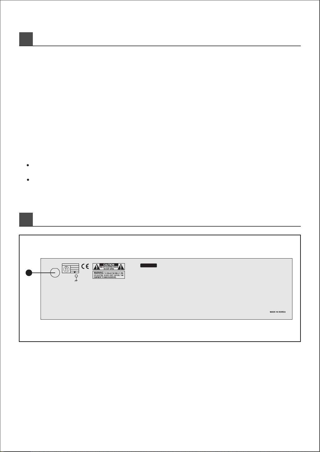
REAR PANEL CONTROLS
38.POWER INLET
For AC power supplying socket, connect AC power cord with safety.
Built in AC fuse in the socket.
( VOLTAGE : 220V/230V/240VAC - T0.5AL 250V, 120VAC - T1A 250V )
33.RECORD OUTPUTS
This is output jack for recording of main mix L/R output level is 0dB(0.775V).
34.GRAPHIC EQ IN/OUT JACKS
This is for amplification of external signal via EQ IN/OUT for the details refer to patch connection drawing.
35.EXTERNAL POWER AMP INPUTS (LEFT/RIGHT)
This is input jack from external mixer for the details refer to patch connection drawing.
36.MAIN MIX OUTPUTS (LEFT/RIGHT)
This is to supply signal with external amplifier for bigger PA for the details refer to connection drawing.
37.POWER SECTION
MAIN POWER SWITCH
Pressing switch "on" will make the power indicating GREEN LED on and supply the power.
PHANTOM POWER SWITCH (48V in globally)
When using condenser microphones pressing switch on, XLR connector of all mono microphones will be
supplied as a group.
WARNING : Before switch "on", adjust volume to counter-clockwise and channel fader to
※
SERIAL NO.:
POWER CONNECTOR
1
2
4
3
1: 24VAC
3: 24VAC
4:
2: COM
38

APPLICATIONS
10
MIX.OUT EQ.IN
Audio Precision PowerAmplifier
0
8
7
64
3
2
1
CHANNEL A
10
9
PROTECT
CLIP
SIG
ON
CHANNEL B
8
7
64
3
2
1
10
9
5
RESET POWER
0
5
AP2000
MIC
LINE
R
L
INSERT
8
9/10
L
R
11/12 RIGHT SEND
MIC
LINE
INSERT
7
MIC
LINE
INSERT
6
LINE
INSERT
5
LINE
INSERT
4
LINE
INSERT
3
LINE
INSERT
2
LINE
INSERT
1
PHONES
200
LEFT
10
+dB
5
U
5
10
20
30
50
OO
dB
10
+dB
5
U
5
10
20
30
50
OO
dB
10
+dB
5
U
5
10
20
30
50
OO
dB
10
+dB
5
U
5
10
20
30
50
OO
dB
10
+dB
5
U
5
10
20
30
50
OO
dB
10
+dB
5
U
5
10
20
30
50
OO
dB
10
+dB
5
U
5
10
20
30
50
OO
dB
10
+dB
5
U
5
10
20
30
50
OO
dB
10
+dB
5
U
5
10
20
30
50
OO
dB
10
+dB
5
U
5
10
20
30
50
OO
dB
10
+dB
5
U
5
10
20
30
50
OO
dB
10
+dB
5
U
5
10
20
30
50
OO
dB
10
+dB
5
U
5
10
20
30
50
OO
dB
G LR
L R
8
11/12
7654321
t
DSP
2 1
3
2 1
3
2 1
3
2 1
3
2 1
3
2 1
3
2 1
3
2 1
3
CHANNEL1
0dB
5
1
2
3
4
9
8
7
6
CHANNEL2
0dB
5
1
2
3
4
9
8
7
6
CLIP SIG PWR PWR SIG CLIP
+
-
POWER
PROTECTION
ON
OFF
BRIDGEABLE STEREO MAIN AMPLIFIER JMA 30 0N
2SPEEDS FAN
FULLPRO TECTION
NEGA TIVE FEEDB ACK SYSTEM
ACTIVE CLIPS
L R
MICMICMICMICMIC
R
L
L
9/10
R
POWER SECTION
PHANTOM
+48V ON
IN
OUT(REC)
AUX
SEND
STEREO
RETURN
TAPE
1
2
R
L
LEFT
R
L
L
R
EQ MIX OUT
VOCAL MIC
SEND
DAT or 2-TRACK DECK
KEYBOARD
POWER0dB
3
6
9
+12
3
6
9
-12
0dB
3
6
9
GRAPHICEQUALIZER
3
6
9
-12
Hz
JEQ-215
+12
25 40 63 100 160 250 400 630 1K 1K6 2K5 4K 6K3 10K 16K 25 40 63 100 160 250 400 630 1K 1K6 2K5 4K 6K3 10K 16K CH1 CH2
CLIP
EQ
40Hz
16KHz
CHANNEL2CHANNEL1 LEVEL
STAGE MONITOR
GUITAR
EFFECTS
BOX
DAT or 2-TRACK DECK
Multi Effect Processor
JMA and POWER SERIES
AP SERIES
LARGE PA SYSTEM
JEQ-215
PRE-SHOW MUSIC
SAXOPHONE
MIC'D
GUITAR
COMBO
SEND
Graphic
EQ Outputs
RTN LEFT
RTN RIGHT
NOISE GATE,
COMPRESSOR,
NOTCH FILTER
PA SYSTEM, STEREO LIVE
MIC'D DRUMS
RTN
RIGHT

HOW TO FIX EFFECT PRO FOR RACK TYPE
11
1. NOISE DETECTOR POWER INDICATOR
When ambient noise detector(JND-011) is connected to pickup input(XRL jack) of rear panel, noise
detector power LED is turned on.
Then, you can confirm that power supply to ambient noise detector is normal.
HOW TO FIX EFFECT PRO
FOR RACK TYPE
HOW TO FIX EFFECT PRO
FOR RACK TYPE
t
DSP
DSP
DSP
DSP
DSP
DSP
DSP
DSP
DSP
DSP
EFFECTPRO
8224
MIXINGCONSOLE
21
3
21
3
21
3
21
3
21
3
21
3
21
3
21
3
8
9/10
MIC
LINE
L
R
L
INSERT
R
MONO
GAIN
Ð30dB
GAIN
Ð15
0
Ð40
Ð20
+10
Ð50
dB
Ð20
Ð45
Ð30
12KHz
HF
100Hz
12KHz
HF
15 15
U
15 15
U
15
U
15
350
MF
3.5K
1K
7K
150
15 15
U
80Hz
LF
U
15 15
80Hz
LF
U
15 15
00
PAN BAL
SGN
CLIP
PFL
SGN
CLIP
PFL
8
9/10
PAD
Ð10
0
+20Ð20
dB
+10Ð15
+5
2.5KHz
MF
LR
LR
00
11/12
L
R
L
R
MONO
GAIN
12KHz
HF
15 15
U
15 15
U
80Hz
LF
U
15 15
0
BAL
SGN
CLIP
PFL
11/12
11/12
Ð10
0
+20Ð20
dB
+10Ð15
+5
2.5KHz
MF
LR
0
9
6
3
0
3
6
9
12
Ð
12
+
9
6
3
0
3
6
9
12
Ð
12
+
9
6
3
0
3
6
9
12
Ð
12
+
9
6
3
0
3
6
9
12
Ð
12
+
RIGHT
300Hz
120Hz
50Hz 2KHz 5KHz 12KHz
LEFT
RIGHT SEND
POWERSECTION
PHANTOM
+48VON
AUX
2
SEND
PRE
IN
OUT(REC)
AUX
SEND
STEREO
RETURN
TAPE
1
2
+9
LEFT RIGHT
+6
+3
0
dB
-
30
-
24
-
18
-
15
-
12
-
9
-
6
-
3
R
L
10
0
PHONES
10
0
AUX
1
SEND
10
0
STEREO
RTN/T
APE
2
10
0
STEREO
RTN/TAPE
1
7
MIC
LINE
INSERT
GAIN
Ð30dB
Ð15
Ð40
Ð20
+10
Ð50
dB
Ð20
Ð45
Ð30
12KHz
HF
100Hz
15 15
U
15 15
350
MF
3.5K
1K
7K
150
80Hz
LF
U
15 15
0
PAN
SGN
CLIP
PFL
7
PAD
LR
0
6
MIC
LINE
INSERT
GAIN
Ð30dB
Ð15
Ð40
Ð20
+10
Ð50
dB
Ð20
Ð45
Ð30
12KHz
HF
100Hz
15 15
U
15 15
350
MF
3.5K
1K
7K
150
80Hz
LF
U
15 15
0
PAN
SGN
CLIP
PFL
6
P
AD
LR
0
5
MIC
LINE
INSERT
GAIN
Ð30dB
Ð15
Ð40
Ð20
+10
Ð50
dB
Ð20
Ð45
Ð30
12KHz
HF
100Hz
15 15
U
15 15
350
MF
3.5K
1K
7K
150
80Hz
LF
U
15 15
0
PAN
SGN
CLIP
PFL
5
P
AD
LR
0
4
MIC
LINE
INSERT
GAIN
Ð30dB
Ð15
Ð40
Ð20
+10
Ð50
dB
Ð20
Ð45
Ð30
12KHz
HF
100Hz
15 15
U
15 15
350
MF
3.5K
1K
7K
150
80Hz
LF
U
15 15
0
PAN
SGN
CLIP
PFL
4
PAD
LR
0
3
MIC
LINE
INSERT
GAIN
Ð30dB
Ð15
Ð40
Ð20
+10
Ð50
dB
Ð20
Ð45
Ð30
12KHz
HF
100Hz
15 15
U
15 15
350
MF
3.5K
1K
7K
150
80Hz
LF
U
15 15
0
PAN
SGN
CLIP
PFL
3
PAD
LR
0
2
MIC
LINE
INSERT
GAIN
Ð30dB
Ð15
Ð40
Ð20
+10
Ð50
dB
Ð20
Ð45
Ð30
12KHz
HF
100Hz
15 15
U
15 15
350
MF
3.5K
1K
7K
150
80Hz
LF
U
15 15
U
0
P
AN
SGN
CLIP
PFL
2
PAD
LR
U
0
1
MIC
LINE
INSERT
GAIN
Ð30dB
Ð15
Ð40
Ð20
+10
Ð50
dB
Ð20
Ð45
Ð30
12KHz
HF
100Hz
15 15
U
15 15
350
MF
3.5K
1K
7K
150
80Hz
LF
U
15 15
A
UX
2
U
0
AUX
1
PAN
SGN
CLIP
PFL
1
P
AD
LR
U
0
PHONES
9/10
8
7
6
5
4
3
2
1
LEFTRIGHT SEND
200
AUX
2
A
UX
1
AUX
2
A
UX
1
AUX
2
AUX
1
A
UX
2
AUX
1
A
UX
2
AUX
1
AUX
2
A
UX
1
AUX
2
A
UX
1
A
UX
2
AUX
1
A
UX
2
AUX
1
U
U
U
U
U
U
U
dB
VUMETER
800Hz
MIX.OUTEQ.IN
LEFT
+
+
+
Ð
Ð
Ð
+
+
+
Ð
Ð
Ð
+
+
+
+
+
+
Ð
Ð
Ð
Ð
Ð
Ð
Ð10
Ð10
0
Ð10
0
Ð10
0
Ð10
0
Ð10
0
Ð10
0
Ð10
0
10
+dB
5
U
5
10
20
30
50
O
O
dB
10
+dB
5
U
5
10
20
30
50
O
O
dB
10
+dB
5
U
5
10
20
30
50
O
O
dB
10
+dB
5
U
5
10
20
30
50
O
O
dB
10
+dB
5
U
5
10
20
30
50
O
O
dB
10
+dB
5
U
5
10
20
30
50
O
O
dB
10
+dB
5
U
5
10
20
30
50
O
O
dB
10
+dB
5
U
5
10
20
30
50
O
O
dB
10
+dB
5
U
5
10
20
30
50
O
O
dB
10
+dB
5
U
5
10
20
30
50
O
O
dB
10
+dB
5
U
5
10
20
30
50
O
O
dB
10
+dB
5
U
5
10
20
30
50
O
O
dB
10
+dB
5
U
5
10
20
30
50
O
O
dB
UU
U
U
U
U
U
U
U
U
U
U
U
U
U
U
U
U
U
U
U
U
U
U
U
U
U
U
U
U
R
L
GL
R
LR
DSP
LEFT
RIGHT
EQMIXOUT
LINE.EQINUT,
MIXOUTPUT
CHANNEL
INSERTAUX1,2OUTPUTSTEREORETURN
INPUT
SRT
S(GND)
T(+)
R(
-
)
SRTSRTSRT
S
T(+)
R(GND)R(RIGHT)
S(GND)
T(LEFT)
S(GND)
T(IN)
R(OUT)
1
2
3
12
3
MICINPUTEQMIXOUT

HOW TO FIX EFFECT PRO FOR RACK TYPE
12
1. NOISE DETECTOR POWER INDICATOR
When ambient noise detector(JND-011) is connected to pickup input(XRL jack) of rear panel, noise
detector power LED is turned on.
Then, you can confirm that power supply to ambient noise detector is normal.
HOW TO FIX EFFECT PRO
FOR RACK TYPE
HOW TO FIX EFFECT PRO
FOR RACK TYPE
t
DSP
DSP
DSP
DSP
DSP
DSP
DSP
DSP
DSP
DSP
EFFECTPRO
8224
MIXING CONSOLE
21
3
21
3
21
3
21
3
21
3
21
3
21
3
21
3
8
9/10
MIC
LINE
L
R
L
INSERT
R
MONO
GAIN
Ð30dB
GAIN
Ð15
0
Ð40
Ð20
+10
Ð50
dB
Ð20
Ð45
Ð30
12KHz
HF
100Hz
12KHz
HF
1515
U
1515
U
15
U
15
350
MF
3.5K
1K
7K
150
1515
U
80Hz
LF
U
1515
80Hz
LF
U
1515
00
PANBAL
SGN
CLIP
PFL
SGN
CLIP
PFL
8
9/10
PAD
Ð10
0
+20Ð20
dB
+10Ð15
+5
2.5KHz
MF
LR
LR
00
11/12
L
R
L
R
MONO
GAIN
12KHz
HF
1515
U
1515
U
80Hz
LF
U
1515
0
BAL
SGN
CLIP
PFL
11/12
11/12
Ð10
0
+20Ð20
dB
+10Ð15
+5
2.5KHz
MF
LR
0
9
6
3
0
3
6
9
12
Ð
12
+
9
6
3
0
3
6
9
12
Ð
12
+
9
6
3
0
3
6
9
12
Ð
12
+
9
6
3
0
3
6
9
12
Ð
12
+
RIGHT
300Hz
120Hz
50Hz 2KHz 5KHz 12KHz
LEFT
RIGHT SEND
POWER SECTION
PHANTOM
+48V ON
AUX
2
SEND
PRE
IN
OUT(REC)
AUX
SEND
STEREO
RETURN
TAPE
1
2
+9
LEFT RIGHT
+6
+3
0
dB
-
30
-
24
-
18
-
15
-
12
-
9
-
6
-
3
R
L
10
0
PHONES
10
0
AUX
1
SEND
10
0
STEREO
RTN/T
APE
2
10
0
STEREO
RTN/TAPE
1
7
MIC
LINE
INSERT
GAIN
Ð30dB
Ð15
Ð40
Ð20
+10
Ð50
dB
Ð20
Ð45
Ð30
12KHz
HF
100Hz
1515
U
1515
350
MF
3.5K
1K
7K
150
80Hz
LF
U
1515
0
PAN
SGN
CLIP
PFL
7
PAD
LR
0
6
MIC
LINE
INSERT
GAIN
Ð30dB
Ð15
Ð40
Ð20
+10
Ð50
dB
Ð20
Ð45
Ð30
12KHz
HF
100Hz
1515
U
1515
350
MF
3.5K
1K
7K
150
80Hz
LF
U
1515
0
PAN
SGN
CLIP
PFL
6
P
AD
LR
0
5
MIC
LINE
INSERT
GAIN
Ð30dB
Ð15
Ð40
Ð20
+10
Ð50
dB
Ð20
Ð45
Ð30
12KHz
HF
100Hz
1515
U
1515
350
MF
3.5K
1K
7K
150
80Hz
LF
U
1515
0
PAN
SGN
CLIP
PFL
5
P
AD
LR
0
4
MIC
LINE
INSERT
GAIN
Ð30dB
Ð15
Ð40
Ð20
+10
Ð50
dB
Ð20
Ð45
Ð30
12KHz
HF
100Hz
1515
U
1515
350
MF
3.5K
1K
7K
150
80Hz
LF
U
1515
0
PAN
SGN
CLIP
PFL
4
PAD
LR
0
3
MIC
LINE
INSERT
GAIN
Ð30dB
Ð15
Ð40
Ð20
+10
Ð50
dB
Ð20
Ð45
Ð30
12KHz
HF
100Hz
1515
U
1515
350
MF
3.5K
1K
7K
150
80Hz
LF
U
1515
0
PAN
SGN
CLIP
PFL
3
PAD
LR
0
2
MIC
LINE
INSERT
GAIN
Ð30dB
Ð15
Ð40
Ð20
+10
Ð50
dB
Ð20
Ð45
Ð30
12KHz
HF
100Hz
1515
U
1515
350
MF
3.5K
1K
7K
150
80Hz
LF
U
1515
U
0
P
AN
SGN
CLIP
PFL
2
PAD
LR
U
0
1
MIC
LINE
INSERT
GAIN
Ð30dB
Ð15
Ð40
Ð20
+10
Ð50
dB
Ð20
Ð45
Ð30
12KHz
HF
100Hz
1515
U
1515
350
MF
3.5K
1K
7K
150
80Hz
LF
U
1515
A
UX
2
U
0
AUX
1
PAN
SGN
CLIP
PFL
1
P
AD
LR
U
0
PHONES
9/10
8
7
6
5
4
3
2
1
LEFT RIGHT SEND
200
AUX
2
A
UX
1
AUX
2
A
UX
1
AUX
2
AUX
1
A
UX
2
AUX
1
A
UX
2
AUX
1
AUX
2
A
UX
1
AUX
2
A
UX
1
A
UX
2
AUX
1
A
UX
2
AUX
1
U
U
U
U
U
U
U
dB
VU METER
800Hz
MIX.OUTEQ.IN
LEFT
+
+
+
Ð
Ð
Ð
+
+
+
Ð
Ð
Ð
+
+
+
+
+
+
Ð
Ð
Ð
Ð
Ð
Ð
Ð10
Ð10
0
Ð10
0
Ð10
0
Ð10
0
Ð10
0
Ð10
0
Ð10
0
10
+dB
5
U
5
10
20
30
50
O
O
dB
10
+dB
5
U
5
10
20
30
50
O
O
dB
10
+dB
5
U
5
10
20
30
50
O
O
dB
10
+dB
5
U
5
10
20
30
50
O
O
dB
10
+dB
5
U
5
10
20
30
50
O
O
dB
10
+dB
5
U
5
10
20
30
50
O
O
dB
10
+dB
5
U
5
10
20
30
50
O
O
dB
10
+dB
5
U
5
10
20
30
50
O
O
dB
10
+dB
5
U
5
10
20
30
50
O
O
dB
10
+dB
5
U
5
10
20
30
50
O
O
dB
10
+dB
5
U
5
10
20
30
50
O
O
dB
10
+dB
5
U
5
10
20
30
50
O
O
dB
10
+dB
5
U
5
10
20
30
50
O
O
dB
UU
U
U
U
U
U
U
U
U
U
U
U
U
U
U
U
U
U
U
U
U
U
U
U
U
U
U
U
U
R
L
GL
R
LR
DSP
LEFT
RIGHT
EQMIXOUT
LINE.EQINUT,
MIXOUTPUT
CHANNEL
INSERTAUX1,2OUTPUTSTEREORETURN
INPUT
SRT
S(GND)
T(+)
R(
-
)
SRTSRTSRT
S
T(+)
R(GND)R(RIGHT)
S(GND)
T(LEFT)
S(GND)
T(IN)
R(OUT)
1
2
3
12
3
MICINPUT EQMIXOUT

SPECIFICATIONS
13
Mixer Section
Inpu Output
Input & Output inpedances Mic inputs(XLR)
Mono 8/Stereo 2 Module, EQ Mix L-R/AUX send 2, Stereo RTN/REC Out
1.8K Balanced
EQ Mix Outpus 600 Balanced
Hi-z & Stereo Input(1/4 jack) Greater than 15K Balanced
Insert Point 600 /16K Unbalanced
AUX Output 600 Unbalanced
Frequency Response
Total Harmonic Distortion Line In To EQ Mix Out
Input & Output Level Mic Inputs Sensitivity(XLR) -20dB to -50dB(Un Pad)
Insert -2dB Nomianl
Line Input Sensitivity(1/4 jack) -20dB to +10dB(Pad)
Stereo Input Sensitivity(1/4 jack) +20dB to -20dB
AUX Return(1/4 jack) +4dB
AUX Options +4dB
EQ Mix Outputs +4dB for 0vu
Recording Outputs 0dB Nominal
Any Input to Any Output
Dimension (WxDxH)
443 x 432 x 106 (mm)
17.5 x 17 x 1.2 (inch)
Weight 7.5kg
Less Than -0.5dB(20Hz~20KHz)
Less Than 0.03% @ 1KHz
Noise Mic Input Equipment Input Noise
(150 Source)
-115dB
Less Than 0.04% @ 10KHz

BLOCK DIAGRAM
14
HIGH
FREQ
MID LOW
200W
<
=
PHANTOM
POWER
HA
HA
HA
HA
HA
HA
HA
LA
LA
LA
LA
L
R
TAPE
INPUT
+48V
NOTICE
: XLR CONNECTOR
: 1/4" PHONE JACK
: PIN JACK
LEFT
RIGHT
EQ MIX
OUTPUT
LEFT
RIGHT
MIX
OUT
LEFT
RIGHT
EQ
INPUT
1
3
2
PAD(30dB)
+48V
GAIN (40dB)
HIGH-PASS
FILTER
100Hz
12dB/OCT
3-BAND EQ
INSERT
POINT
ACTIVE
DETECT
FADER PAN
AUX-1
PFL
CLIP
PFL
SGN
MIC/LINE
-60dB~+20dB
MIC/LINE
MONO INPUT
LEFT BUS
3-BAND EQ
3-BAND EQ
MONO
HIGH MID LOW
ACTIVE
DETECT
CLIP
PFLSGN
BAL
FADER
PFL
STEREO INPUT
SUPPLY
POWER
L
-20dB~+20dB
R
STEREO
RETURN 1
AC POWER
120V/220V/230V/240V
50/60Hz
(OPTION)
PHONES
LEVEL
L-FADER
GAIN
POWER
AUX-2
AUX-1
STEREO
DSP
AUX-1
AUX-2
AUX-1
EFFECT
L
STEREO
RETURN 2
R
R
TO MIXER
METER DISPLAY AMP
MIX & PFL
METER
+
Ð
+
Ð
1
2
R-FADER
AUX 1
AUX 2-F
7-BAND EQ
L
R
REC
OUT
AUX
SEND
RIGHT BUS
AUX 1 BUS
AUX 2 POST
PFL
PFL CON
DSP
POWER
MUTE
AUX 2 PRE
LEFT BUS
RIGHT BUS
AUX 1 BUS
AUX 2 POST
PFL
PFL CON
DSP
AUX 2 PRE
PRE
L
Table of contents


