Sound Devices 552 User manual

!"#$%&'()*+(,& --.&/-&+01$$(2&3*4(5&6.&751+8&5(+"5%(5
552
Quick Start Guide
This Quick Start Guide provides a brief overview for first use of the 552.
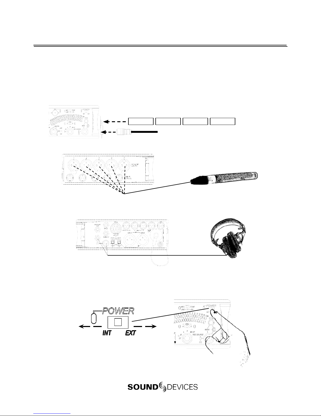
1) Connect power.
For internal powering from AA batteries, unscrew the battery cap (counter-clock-
wise), insert four AA batteries (not included) positive (+) side first into the battery
tube. Thread the battery cap back on (clockwise). For external powering, connect
a DC powering source (not included) to the DC connector on the Right Panel.
External Power Supply (not included)
2) Connect analog microphoneor line sources to the XLR inputs.
552Left Panel
+
AA
-
+
AA
-
+
AA
-
+
AA
-
3) Connect headphones to either the 1/4-inch or the 3.5 mm headphone outputs.
552 Right Panel
4) Power On the mixer.
Slide the power switch to the INT position to power the mixer from AA batteries.
Slide the power switch to the EXT position to power the mixer from external DC.
Slide left for Internal AA Battery
Slide right for External DC Power

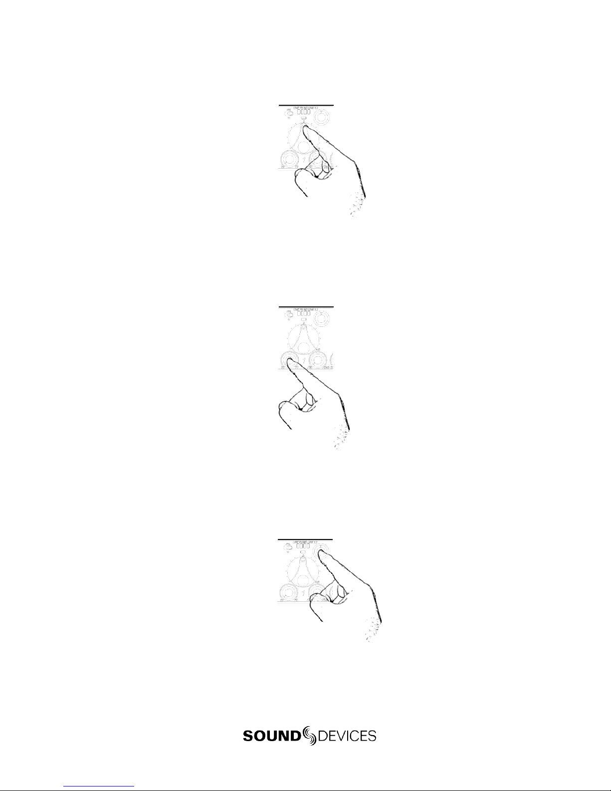
5) Set Input Type –Mic or Line Level.
To select an input to Mic or Line level, hold an input’s PFL switch, then slide the
SLATE MIC/TONE switch to the left. The input’s LINE LED illuminates blue when
set to line level and the LED is not illuminated when set to Mic level.
1) Hold the Input’s PFL. 2) Slide the SLATE MIC/TONE switch left.
6) ApplyPhantom Power to an input.
The 552 supplies 48 V to inputs set to receive phantom power (PH). Phantom
pow- er can be set to 12 V in the Setup Menu. To apply phantom power, hold an
input’s PFL switch, then slide the SLATE MIC/TONE switch to the right. The
input’s PH LED illuminates blue when phantom power is applied.
1) Hold the Input’s PFL. 2) Slide the SLATE MIC/TONE switch right.
7) Select aheadphone monitor mode using the HeadphoneSelector.
Stereo (Left and Right) Program
Right Program
Left Program
Stereo MS (mid-side)
Recording Source
Mono (summed left and right)
L
M
ST
RMS ST
REC Source
MS Monitor Modes are useful to listen to left/right stereo whenM and S signals are routed. When
inputs are linked as an MS pair in the Setup Menu use the ST (Stereoprogram) monitor mode; this will
already contain the decoded MS Stereosignal.
8) Set the headphone level.
Turn the Headphone Controller to set headphone levels.The currently selected
headphone leve l is briefly indicated on the right output meter when the Head-
phone level control is turned.
552
9) Set Input Faders in use to unity gain (0 dB or 12 o’clock).
Faders not used should be set to off (full counter-clockwise position).
10) Set Input Trim Levels.
Push to release the recessed Trim (gain) Control. Turn the Trim Control clockwise to
raise the level of the input. Once the gain has been set, push the Trim Control again
to recess the control and remove it from the mixing surface. Use the Input Fader to
make fine level adjustments.
11) Routeeach input to either Left or Right Outputsusing the Input Pan Control.
Push to release the recessed Pan Control. Turn counter-clockwise to send the input
to the Left Output and turn clockwise to send it to the Right Output. Once the pan
has been set, push the Pan Control again to recess the control and remove it from
the mixing surface.
12) Set High-Pass Filters and Limiters.
Set the High-Pass Filter using the control adjacent to the Trim Control (full counter-
clockwise position is off). Activate the Limiters using the switch adjacent to the
Master Output Gain Control (Lim (dual Mono) Link (Stereo) applies to all inputs
and outputs).
13) Adjust LED Meter brightness.
Press and hold the Battery Check button while turning the Headphone Controller.
14) Check Internal and External power levels.
Press the Battery Check button to display the internal and external power
levels on the Output Meter LEDs. The internal AA battery level is displayed on the
left meter and external DC voltage level is displayed on the right meter.
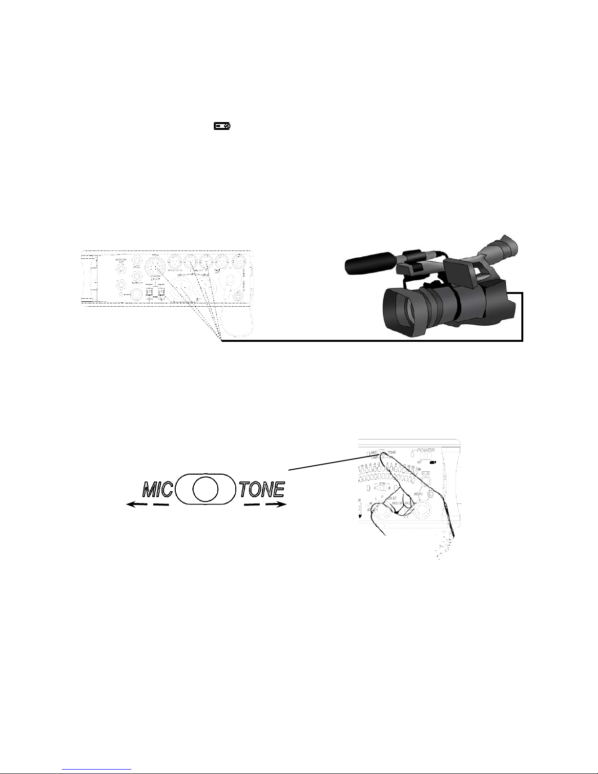
15) Connect the 552 analog outputsto the next device in the signal chain (audio
recorder, wireless transmitter, or camera).
Output levels are set (Line, -10, Mic) using the respective output’s attenuation
switch.
552 Right Panel
16) Set the next device’s input sensitivity to receive the supplied signal.
17) Activate the 552’s Tone Generator.
Slide the SLATE MIC/TONE switch to the TONE position. Tone latches on if the
switch is held for two seconds; slide right again to turn off. A 1 kHz tone is gener-
ated and is sent out at 0 dB (level and frequency are menu-adjustable).
Slide left for Slate Mic
Slide right for Tone.
18) Adjust the input gain on the next device accordingly.
552
19) Setting the Time and Date.
Press and hold the Battery Check button for the mixer to announce in headphones
the current time and date. If the setting spoken back in headphones is in correct
see Time of Day/Date Clock section of the 552 User Guide.
20) Insert an SD memory card into the back panelSD Slot.
Remove the protective rubber cover to access the SD memory card slot. Insert the
SD card into the slot until it sits securely in the slot. The card should glide smoothly
into the slot. Do not use excessive force when inserting the card and make certain
that the electrical contacts are facing downwards. Push on the card to remove it.
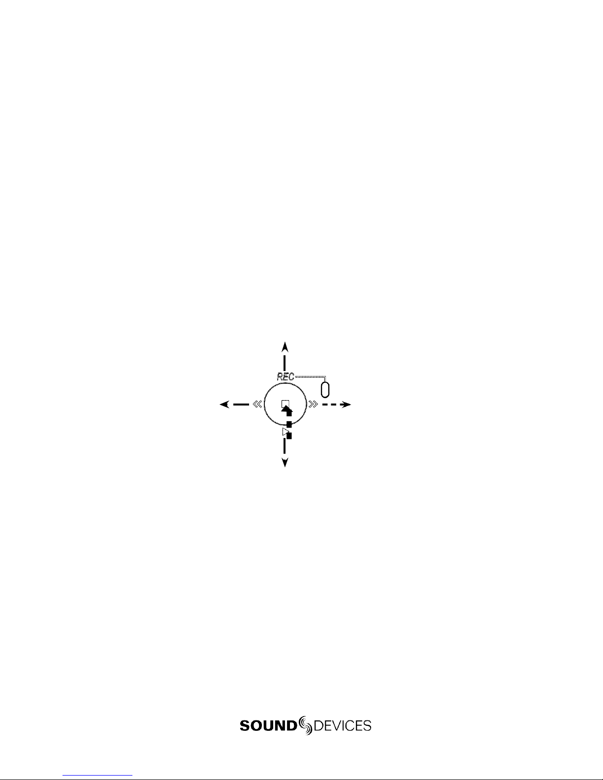
21) Controlling the Integrated Digital Recorder.
The Recorder Controller is used to initiate the Record, Stop, Playback, Rewind, Fast
Forward functions as well as to navigate through recorded files.
Press in to Pause/Stop
Push down to playback the last recorded file or loaded file.
Push left to load the previous file.
Push left to Rewind during playback.
Push right to load the next file.
Push right to Fast Forward during playback.
Push up to begin recording.
22) Making Changes in the Setup Menu.
The 552 has many features that are accessed through its Setup Menu. For details on
entering and controlling the Setup Menu see Accessing the Setup Menu section in
the 552 User Guide.
23) Power Down the Mixer.
Slide the power switch to the ce nter position to po wer do wn.All settings are saved
to EEPROM and will be saved and recalled upon next po wer on whether or not
the unit is powered or has batteries.

552
Voice Prompt
The 552 features a Synthetic Voice for EnhancedNavigation, or SVEN. SVEN provides spoken word
feedback when Setup Menu features are adjusted. He is designed to simplify control and provide
important information to the user. Additionally, SVEN provides status information about the digital
audio recorder and time and date information. SVEN is routedonly to the headphone outputs.
The following information is reported by theSVEN.
The 3.5 mm headphone output does not receive SVEN announcements when Talk Back Mode is active.
Function Description
C
ard Space Available
P
ress andhold the Battery Check button to announce the remaining card space available. SVEN
au
tomaticallyannounces remaining record time at 15,10, 5, and 2 minutes remaining.
T
ime and Date
C
ontinue to hold the Battery Check button after Card Space Available announcement to hear the
c
urrent time anddate.
T
ime Date Set
H
old Input 5’s PFL then press the Battery Check button and the Headphone Controller to enter
T
ime Date Set. The unit of timeandeachvalue is announced when turning Headphone Controller
.
S
etup Menu Navigation
W
hile in the Setup Menu, the currentFunction or Option is announced witheachturn of the
H
eadphone Controller.
P
layback Navigation
A
nnounces the file number of the selected file. If navigating through folders, SV E Nannounces t
he
s
elected daily folder.
M
edia Busy Indication
“
Media Busy” is announced if the SD card is not available torespondto acommand.
Fu
ll SD Card
“
Full SD Card” is announced when thereis no space remaining on the SDcard and a record com
-
m
andhasbeen given.
R
ecord Mode Off
“
Record Mode Off”is announced if the recorder receives a commandand the recorder is disabl
ed
i
n the Setup Menu.
N
ext File
P
ress the Recorder Controller instand-by mode to announce the file number of the next take to
b
e recorded.
552 User Guide
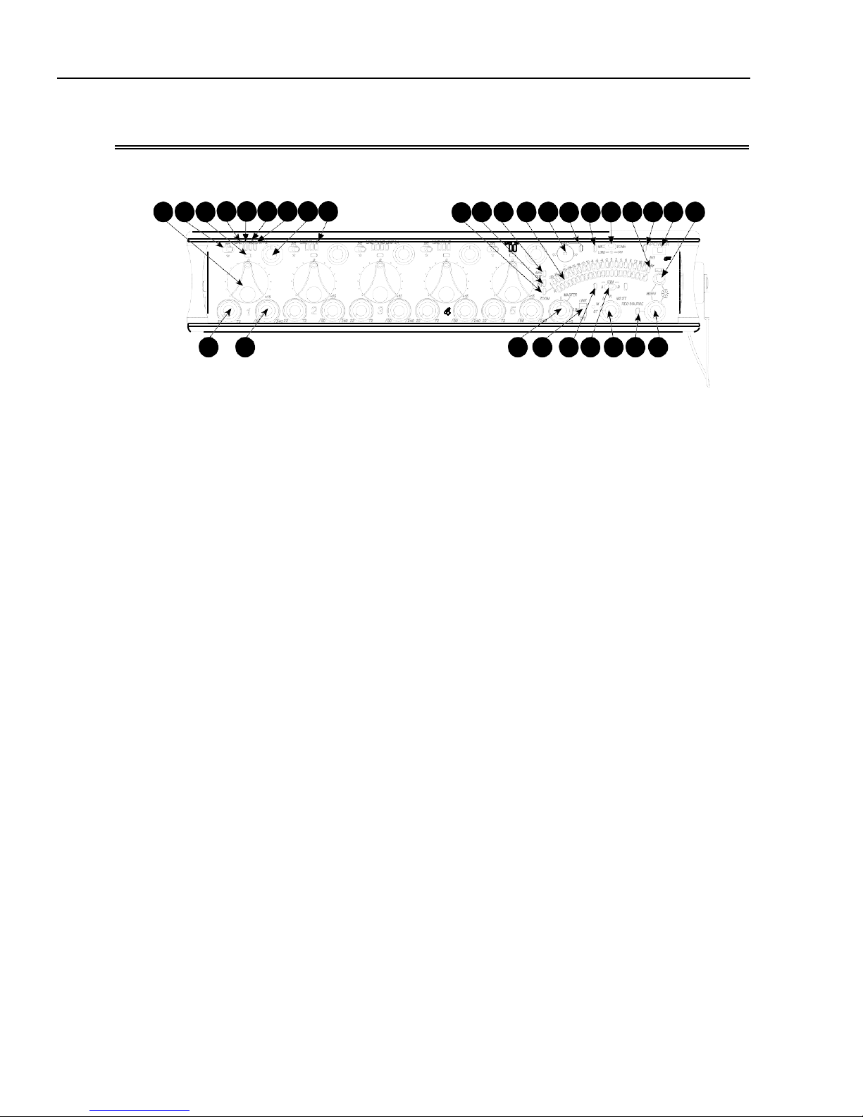
FrontPanelDescriptions
All 552 settings are accessed and controlled from the Front Panel. This allows the unit to be placed in
a production bag while having completecontrol of the unit.
1456789 10 11 12 13 14 15 16 17 18 19 20 21 22 23
2 3 24 25 26 27 28 29 30
1) Input Fader
Primary control for adjusting the level
of an input during operation. Ranges
from Off to +15 dB. Nominal setting is
in the middle (0 dB).
2) Gain(Trim)
Coarse input gain control. Sets the
initial input sensitivity level so that the
Input Fader can be used for fine gain
adjustments. Rangeis from +22 dB to
+72 dB. See Input Setup and Control.
3) High-PassFilterControl
Adjusts corner (-3 dB) frequency of
high-pass filter. Full counter-clockwise
position (detented) deactivates the
High-Pass Filter. Range is 80-240 Hz,
12 dB/oct to 6 dB/oct. See Input Setup
and Control.
4) PFL/Input Solo Switch
Pre-Fade Listen. Sends the input’s
pre-fade signal to headphones for solo
monitoring, troubleshooting, and gain
setting. Does not affect Master Output
signal. Slide the switch left to activate,
and again to deactivate. For momen-
tary action, hold the switch left for one
second or longer. The Input Signal Ac-
tivity LED flashes yellow when an in-
put’s PFL is latched on. The Input PFL
Switch is also used to make changes to
several input settings. See Input Setup
and Control.
5) Input Signal LED
Indicates input signal activity. LEDs il-
luminate in various colors and intensi-
ties to show signal level andactivity.
Green = signal presence (pre-fader),
yellow = limiter activity (pre- and post-
fade) also flashes when solo is latched
on, red = signal overload/clipping
(pre- and post-fade) also solid when
input is muted. See Metering.
6) Mic/LineLED
Illuminates blue to indicate aninput is
set to Line level. To toggle between Mic
and Line settings, hold theinput PFL
then slide the Slate Mic/Tone Switch to
the Slate position.
7) PH/Phantom LED
Illuminates blue to indicate aninput’s
phantom power is on. To toggle phan-
tom power on and off, hold the selected
input’s PFL switch then slide theSlate
Mic/Tone switch to the Tone position.
Phantom power voltage can be set to
12 or 48 V (48 V is Factory Default).
Phantom voltage is set in the Setup
Menu. The phantom power voltageis
applied across all inputs with the PH
LED illuminated.
8) MSLED
Inputs 1, 2 and 3, 4 can be linked as an
MS pair. When a pair is linked, the MS
and LINK LED illuminate blue. Stereo
linking configurations are selected in
the Setup Menu. See Stereo Linking.

552 UserGuide
9) LinkLED
Illuminates blue when Inputs are link e d
as a stereo pair. Stereo linking configura-
tions are selected in the Setup Menu.See
Stereo Linking.
10) Input Pan
Controls the Left/Right balance of the
input signal to the outputs.
11) Input Polarity (Inputs 2and4only)
Illuminates blue when the Input’s polar-
ity is reversed. To toggle the state of the
input polarity, hold the selected input’s
PFL then press the Battery Check button.
12) ZoomLED
Illuminates blue when the Output Meter
is in Zoom Mode. Zoom Mode allows
the user to view higher resolution in the
0 to +20 dBu range on the Output Meter.
To toggle Zoom on and off, press in on
the Headphone Controller. The Zoom
Function is defeated in the Setup Menu
Function Meter Ballistics. SeeMetering.
13) Time Code LED
Time Code is selected from the Setup
Menu. When on, the LEDflashes blue
when Time Code is active but not being
received The LED Illuminates solid blue
when the unit is receiving valid time
code. Time Code is connected tothe
RTN B TA3 connector and is stamped to
files generated by the552’s recorder. See
Time Code.
14) AES Out LED
Illuminates blue when one or more of
the AES outputs is active. See Digital
Outputs.
15) Output Meter
Multi -se gm en t LED output meter. Scale
is normally -30 dBu to +20 dBu.In Zoom
Mode, scale changes from 0dBu to
+20 dBu. To engage Zoom mode, press
in on the Headphone Controller. See
Metering.
16) Recorder Controller
Controls the Integrated Digital Re-
corder. Record Mode is enabled in the
Setup Menu. When enabled, push up
to Record, press in to Pause/Stop, push
down to Play, push lefttoRewind,push
right to Fast Forward. See Digital Audio
Recorder.
17) Record LED
Indicates the status of the recording me-
dia. The LED is off when the recorder is
in standby mode. Flashes yellow when
no SD card is inserted. Illuminates solid
red while recording, flashes red when
record is pending. Illuminates solid
green while in playback mode. Flashes
green while playback is paused. Illumi-
nates solid yellow when mediais busy.
The LED is off when recorder is off.
18) Slate/Tone LED
Illuminates yellow wheneither the slate
mic or tone is latched on.
19) SlateMic/Tone Switch
Slide left to activate the Slate Micro-
phone, slide againto deactivate. For
momentary action hold for one second
or longer. Slide Slate Mic/Tone switch
right to activate the Tone Oscillator. Tone
will latch if held for 2 seconds or longer,
slide again to deactivate. This switch
also functions as input type and phan-
tom power select. See Tone Oscillator/
Slate Mic. See alsoTalk Back for additional
features.
20) Limiter LED
Each Output has its own Limiter LED.
The LEDs Illuminate yellow when the
Output Limiter is active. See Output
Limiter.
21) Power LED
When powering with internalAAbat-
teries, the LED illuminates green when
the 552 is on, turns yellow when low
voltage point is reached, and flashes
red when voltage reaches a critical level
and batteries should be changed. When
powering with external DC, theLED
illuminates green when the552 is on,
flashes red when voltage drops below
the set threshold. See Powering.

552 User Guide
FrontPanelDescriptions
1 4 5 6 7 8 9 10 11
2 3 24 25 26 27 28 29 30
12 13 14 15 16 17 18 19 20 21 22
23
22) Power Switch
Three-position slide switch, selects be-
tween internal battery power or external
DC sources, middle position is Off.
23) Battery Check Button
Press to display internal and external
voltage levels on the Output Meter.
Secondary function acts as shift key for
various front panel features. Press and
hold to announce card space available
and current time and date.
24) Master Output Level Control
Controls the overall signal level of the
Master Stereo Outputs. Adjustable from
off to +6 dB. See Outputs.
25) Limiter Switch
Activates both Input and Output Limit-
ers. When LIM is selected, the Output
Limiters act independently on the Left
and Right Outputs. When LINK is
selected, the Output Limiters are linked
and limiting is applied evenly across the
Stereo Outputs. See Limiter.
26) RTN A/B LED
Indicates the activity for each return
input. The LEDs illuminatein various
colors and intensities to indicate the be-
havior of the return signals. Green = re-
turn signal presence, Red = return signal
overload/clipping, Yellow = the monitor
return is latched on. When time code is
active, the TA3 input is used exclusively
for time code. The 3.5 mm jack functions
normally. See Return.
27) RTN A/B Switch
Two-position momentary switch. Slide
left for RTN A headphone monitoring,
slide right for RTN B headphonemoni-
toring. Slide again to deactivate. For mo-
mentary action, hold for one second or
longer. While holdingthe return switch,
turn the Headphone Controller to adjust
RTN A and RTNB levels. Whentime
code is active, the TA3 input is used ex-
clusively for time code. The 3.5mm jack
functions normally. See Return and also
RTN Loopback and Time Code.
28) Monitor Selection Switch
Selects program sent to the headphone
monitor. ST = stereo program, M =
mono summed mix of Left and Right
program, L = mono mix of Left program,
R = monomix of Right program, MS
ST = decoded MS Stereo, REC Source =
program routed to the recorder (AES A).
See Headphones.
29) Headphone Pea k LED
Illuminates red when theheadphone
monitor is approaching clip levels.
30) Headphone Controller
Controls headphone gain. Secondary
functions include Setup Menu control,
Zoom Mode, LED Brightness adjust-
ment, and Return levels control.
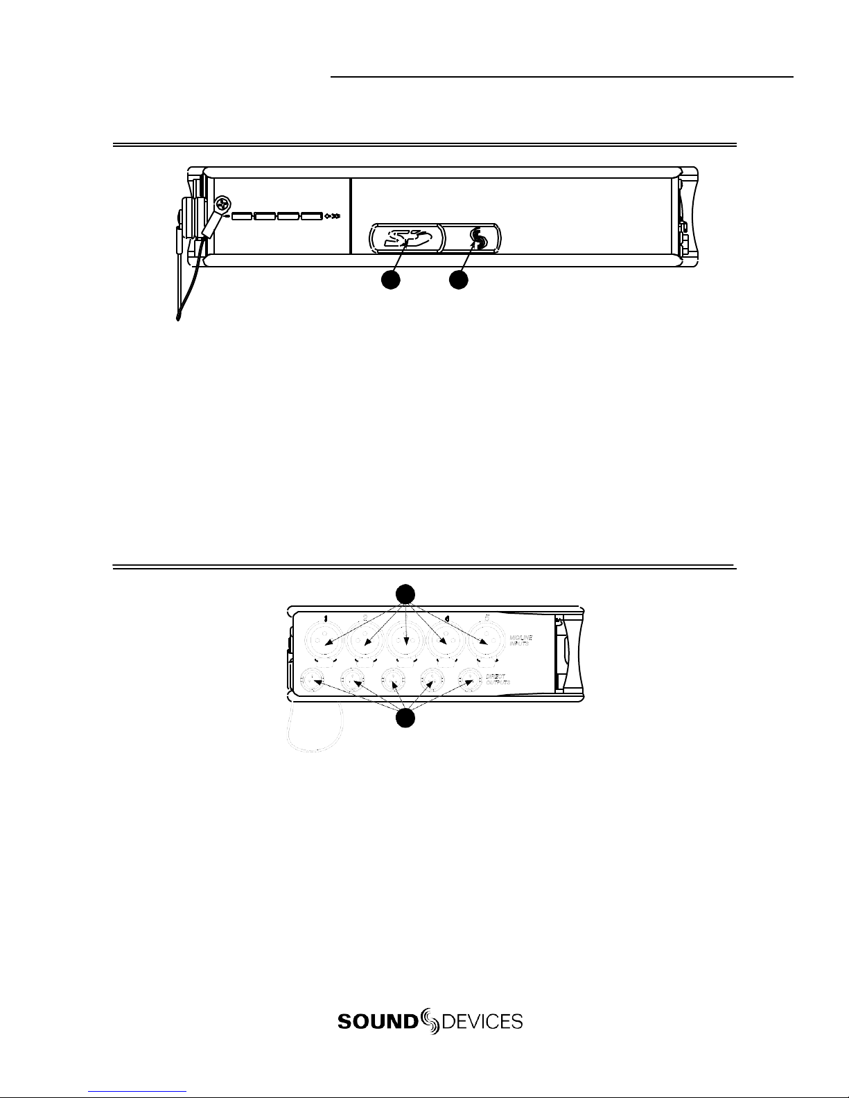
552 UserGuide
RearPanelDescriptions
1 2
1) SD Slot
Protective rubber cover for SD (Secure
Digital) memory card slot. Insert the
SD/SDHC card into the slot until it sits
securely in the slot. The card should
glide smoothly intothe slot. To remove
the card, push to eject. MMC and SDXC
cards are not supported.
1) Factory ProgrammingPort
Mini USB port used for initial factory
programming. This connection has no
user function.
Left Panel Connectors and Controls
1
2
1) Analog Inputs Channels1-5
Transformer-balanced analog micro-
phone-or line-level inputs 1-5 on XLR
connectors. Pin 1 = Ground; pin 2 = Hot
(+); pin 3 = Cold (-). For unbalanced
inputs, tie pin 1 and pin 3 together =
ground, pin 2 = positive. Make cer-
tain phantom power is off when using
unbalanced inputs.See Input Setup and
Control.
2) Analog Direct Outputs
Balanced direct outputs on TA3 con-
nectors. Slate Mic and Tone signals
appear at the direct outputs. Direct
output signal is pre- or post-fader and
level is selected in the SetupMenu be-
tween Line, -10, and Mic levels. Pin 1 =
Ground; pin 2 = Hot (+); pin 3 = Cold (-)
float pin 3 to unbalance.
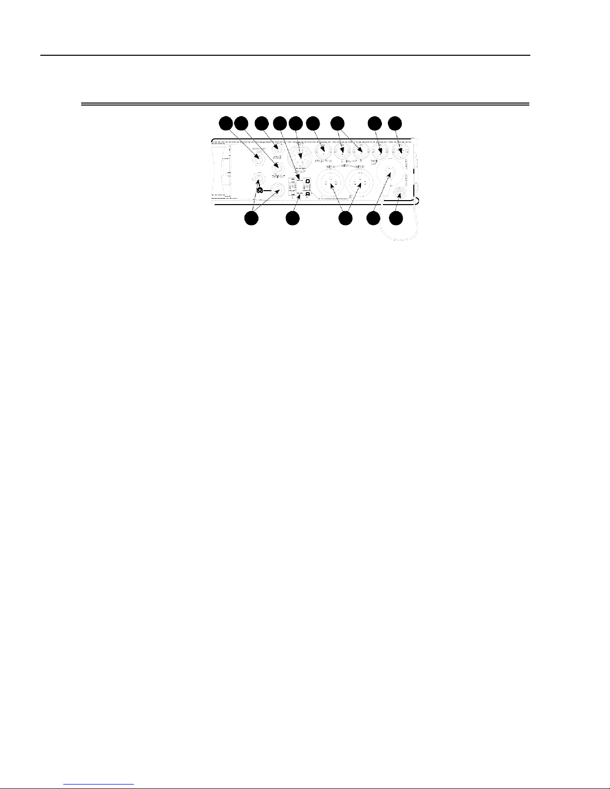
552 User Guide
RightPanelConnectorsandControls
1 2 3 4 5 6 7 8 9
10 11 12 13 14
1) Mono MicOut
Unbalanced mono mic-leveloutput on
3.5 mm female connector, designed to
connect to wireless IFB transmitters or
transcription recorders. Tip = Hot (+),
Sleeve = Ground.
2) Tape Out
Unbalanced stereo output on 3.5 mm
female connector. Sleeve = Ground,
Tip = Left, Ring = Right.
3) RTN BIn
Unbalanced stereo 3.5 mmfemalecon-
nector for Return B audio input. Sleeve
= Ground, Tip = Left, Ring= Right. See
RTN B and RTN Loopback Mode.
4) 10-Pin Output Level Switch
Selects the Hirose 10-Pin Output level
between Line,-10, or Mic levels.
5) 10-Pin Master OutputsandReturnA
10-pin connector includes second master
output (transformer-isolated from the
XLR outputs) and unbalancedstereo
Return A. Can be set to send out AES
digital signals. See AES Digit Outputs.
6) RTN B /TCInput
Unbalanced stereo input for Return B
audio and Time Code input on TA3 con-
nector. RTN B wiring pin 1 = Ground,
pin 2 = Left, pin 3 = Right. TimeCode
wiring pin 1 and 3 = ground, pin 2 = Hot
(+). See Time Code.
7) TA3 Master Outputs
Line, -10, or Mic level se l e cted in the
Setup Me n u.Pin 1 = Ground, pin 2 =
Hot (+), pin 3 = Cold (-) float pin 3to
unbalance.
8) Tape Output
Unbalanced tape-level stereo output
on TA3 connector. Pin 1 = Ground,
pin 2 = Left, pin 3 = Right.
9) LinkI/O
Used to link additional Sound Devices
552, 302, 442, or MixPre mixers.See
Mixer Linking.
10) Headphone Outputs
1/4-inch and 3.5 mm stereo connectors,
drive headphones from 8-2000 ohm
impedances. 3.5 mm connection can be
set in the Setup Menu as an independent
boom operator send. See Talk Back Mode.
11) XLR OutputLevel
Sets the nominal output level for the
Left and Right XLR Master Output to
Line, -10, or Mic levels.
12) XLR Master Outputs
Transformer-balanced analog out-
puts on standard 3-pin XLR connec-
tors. Pin 1 = Ground; pin 2 = Hot (+);
pin 3 = Cold (-). Unbalance by tieing
pin 3 to pin 1. Can be set to send AES3
digital signals in the Setup Menu. See
AES Digit Outputs.
13) Battery Compartment
Holds four AA batteries required for
internal powering. Accepts Lithium,
Alkaline, and NiMH rechargeablecells.
14) DC Input
Accepts DC voltages from 10–18 V for
mixer powering. Pin 1 = Negative (–),
pin 4 = Positive (+). Ext DC is complete-
ly isolated (floating) from the rest of the
circuitry.
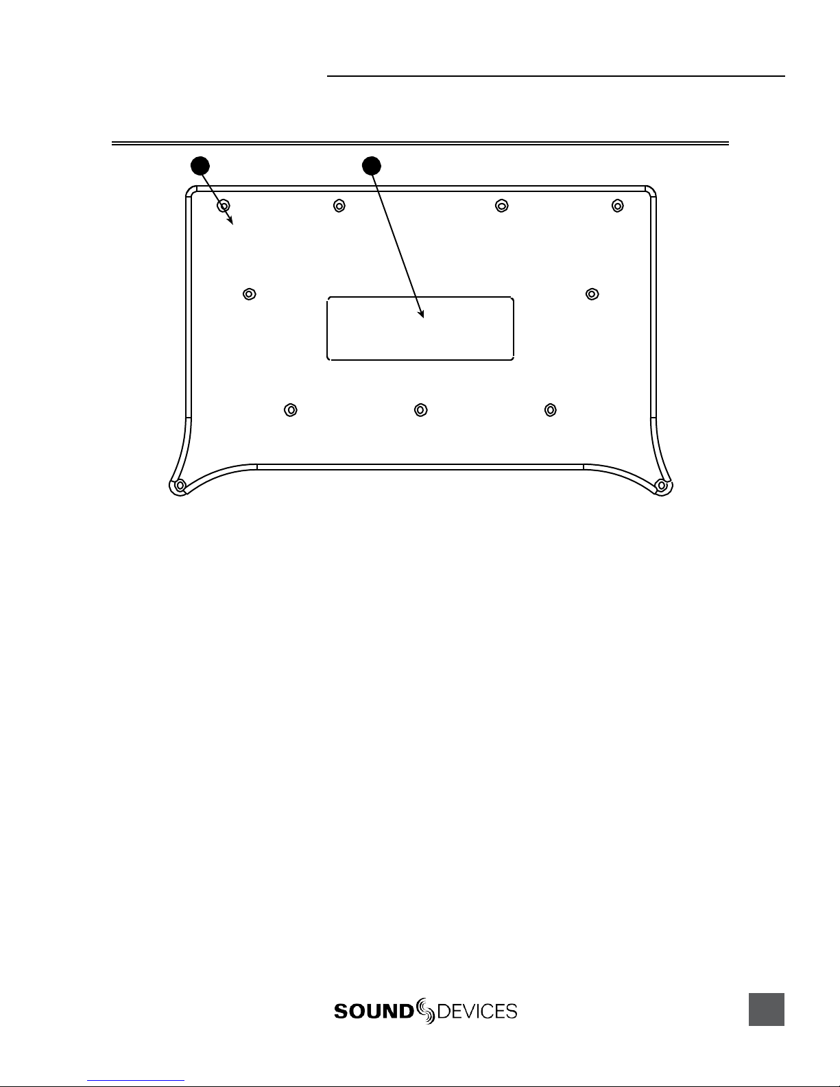
552 UserGuide
TopandBottom Panels
13
1 2
1) Top andBottom Panels
Made of molded carbon fiber, this highly
specialized composite has nearly identi-
cal strength-to-weight properties as
die-cast magnesium. Additionally, the
material also has the natural RF shield-
ing abilities similar to aluminum.
2) ProductBadge
The product badge on the bottom panel
can be covered with a customized iden-
tity tag. The label place holder on the
bottom panel conforms to the 4” x 1.33”
Avery label #5162standard. Third party
software for Avery label #5162 templates
are availableonline.

!"#$%&'()*+(& 99:&6.&;*+ <&.&=*$(&*$&6:&751+8&5(+"5%(5

744 -Quick Start Guide
The 744T is an extremely powerful and flexible portable audio recorder. Before recording, please
familiarize yourself with the product. Several settings should be verified or set based on individual
recording needs.
Powering the Unit
1. Apply power to the unit by attachingthe (included) removable, rechargeable Li-ion (lithium ion) bat-
tery to the back panel battery mount. The metal tabs on the mount line up with the electrical contacts
on the battery. Fromthe factory, the battery may not have a charge, so external DC maybe needed for
initial operation and charging. Connect the included AC-to-DC pow er a dapt er to the DC i nput pl ug to
power and charge the ba t ter y.
2. Press and hold the power key to turn on the unit. Press and hold the power key to turn off the unit.
If this is the first time the recorder has been powered, or if it has been without a battery for an ex-
tended period, the date and time may need to be set.
Charge the included Li-ion battery for 6 hours prior to initial use.
Menu Navigation Basics
The setup menu provides options for recording, routing, and control parameters. The single layer
menu structure allows for very quick navigation andselection of functions. To enter the setup menu
press the front panel key. Once in thesetup menu,the followingconventionsare shared for
navigating among selections andto select specific parameters.
• - enters setup menu
•ITEM-highlighted menu item
•4- selects highlighted item or parameter
• - moves up in menu and between menu parameters
• - moves down in menu and between menu parameters
•8- exits the selected menu or menu altogether
•The stop key will exit from any menu and cancel any changes. Use it to escape out of the
setup menus.
The right panel Rotary Switch (labeled“Select”) is a convenient control to quickly navigateamong
menu items and item options. Its push-to-select function duplicates the check mark in most menus.
Connecting Audio Sources
1. Connect audio sources, either analog or digital, to the appropr ia te i nput co nnec tor.
2. When using either input XLR, set the appropr ia te i nput l evel—mic, line, or digital—with the adjacent
slide switch.
3. If mic-level inputs are used on XLR input 1 or XLR input 2, make certain that phantom power, input
limiters, and high-pass filters are activated as required.
4. When using inputs 3 or 4, set gain levels in the setup menu.

744T UserGuideand TechnicalInformation
Routing Inputs to Tracks
Before recording, inputs must be assigned to tracks. Each of the 744T’s four inputs (1, 2, 3, 4) can be
assigned to any of the four tracks (A, B, C, D). These 256 possible routing combinations are shown
on the front panel with 16 blue LEDs. Illuminated LEDs indicateinput-to-track assignment.
1. Press and hold the STOP key then press the INPUT key to cycle through factoryrouti ng pre-
sets. The 744T has six often-used presets for quick setup of input-to-tr ack routing combinations. Note
the routing combinations on the blue LEDs with each successive press.
2. If none of the preset routing combinationsare suitable, assign a custom routing. Sequential presses of
the input key will eventually cycle tothe customrout i ng opti o n ( see Input to Track Routing, pg. 18).
From the custom input routing menu any input can be assigned to any track, includingmultiple inputs
assigned to a single track.
3. Press EXIT to leave input routing mode.
If no input is assigned to a track the 744T will not record.
Selecting Recording Parameters and File Destination
For most productions, the generalrecording parameters of bit depth, sampling rate, media selection,
and file format are infrequently changed. Enter the setup menuto verify recording settings. Bit depth
and sampling rate aredisplayedon the LCD panel.
1. Select the bit depth as needed.
2. Set the sampling rate as needed.
3. Select the file type, WAV mono or WAV poly, FLAC, MP2, or MP3.
4. Select the storage medium(s) (Internal hard drive, CompactFlash, External drive, or any combinations
of the three drives) for recording.
Time Code Setup
When using a time code workflow, proper time code setup is essential for accuracy. Skip this section
if time code is not being used.
1. Select a time code frame rate appropriate for your project. For film production, typical the time code
rates are 30 fps non-drop (US ) or 25 fps (EU). For s ta ndard definition video project s, us e ei ther 29 .97 or
29.97 non-drop. Fo r high-defini tion projects, use either 23.976 or 29.97.
2. Select the time code run mode: free run, record run, 24 hr. run, or one of the external run modes.
3. Use the 744T as the master clock source and jam time code to all other recording devices. T his will
assure that every device is using the same time reference. (See Time Code for additional information on
time code setup).
Recording
With file parameters set, you are ready to begin recording. The 744T is a record-priority device—
pressing the record key cancels all functions, except file-based operations, and immediately begins
recording a new file. When record is pressed, thered record LED illuminates to confirm record
mode. The filename on the LCDdisplay shows the currentlyrecorded file. Push and hold the
STOP key to end recording.
Playback
When recording is stopped, the most recentlyrecorded file is immediately available for playback.
Press the key tobegin file playback from the beginning of the file.

To select a file for playback:
1. Press and hold the File Viewerkey to select a drive and folder (directory) for playback. The last
file recorded is the default file ready for playback. The default playback source is the storage volume
highlighted on the LCD display.
2. Use the Rotary Switch, or the arrow so ft-keys , to navi ga te t hrough t he F i le Viewer.
3. Once a file is highlighted, press the play key to begin playback.
When playback has finished, the filename willbegin flashing. Use the fast-forward key or
rewind key to step through files in thefolder, or press the stop key to exit playback mode.
FireWire File Transfer to Computer
Sound Devicesstrongly recommends shutting downequipment before connecting to or from any FireWire
device with a connection that carries power (6-pin). Reports have come to our attention of isolated
problems when hot-plugging IEEE 1394(FireWire) devices. (Hot-plugging refers to making con- nections
when one or more of the devices—including the computer—is on.) When hot-plugging, there are rare
occurrences where eitherthe FireWire device or the FireWire port on the host computer isrendered
permanently inoperable. From our experience, anyFireWire connection which carries power issusceptible
to this type of damage.
When connected via FireWire (IEEE-1394a) to a Mac OS or Windows OS computer (see Specifications
for computer requirements), theinternal hard drive and CF card mount onto a computer as “letter”
accessible mass storage volume. Use the appropriate FireWire cable (6-pin to 4-pin or 6-pin to 6-pin)
for interconnection. Files on the 744T can be treated as if they are local files, including renaming files,
copying, deleting and playing directly from the 744T hard drive.
In general, it is good practice to copy audio files from the 744T to a computer before any processing is
performed on the files.
To connect the 744T for FireWirecomputertransfer:
1. Stop all playback and recording activity.
2. Make certain the 744T battery is fully charged, o r connect t o ex ter nal DC.
3. Connect the 744T to the host computer with a FireWire cable.
4. Initiate connection to the computer by accessing the FIREWIRE: CONNECTION menu option in the
Setup Menu. Select COMPUTER/CONNECT or ifthis has already been selected simply hit STOP then the
HDD key to initia te a connection to the computer. The 744T will enter FireWire transfer, indicated by
FIREWIRE CONNECTION on the LCD display. All functions of the 744T are stopped while the 744T is
connected to a computer through F i reWire.
5. Navigate to either the CF card or hard drive from the co mputer and copy a ll needed a udi o filesto local
storage on the computer.
To avoid any possible directory corruptionon the 744T do not interrupt the connection process and
always properly dismount the drivesfrom the operating system. On Mac OS platforms, drag the drive
icons to the trash. On Windows platforms, use the “Disconnect External Media” icon in the system tray.
Dismount the 744T after file transferby “ejecting” the volume from the computer. In Mac OS, drag
the disk icon from the desktop tothe trash or hit -e. In Windows OS, highlight the diskicon, right-
click, and select “eject”. It is best practice to “eject” the 744T volumefrom the computerto maintain
file integrity (see FireWire File Tran s fer ).
744T UserGuideand TechnicalInformation
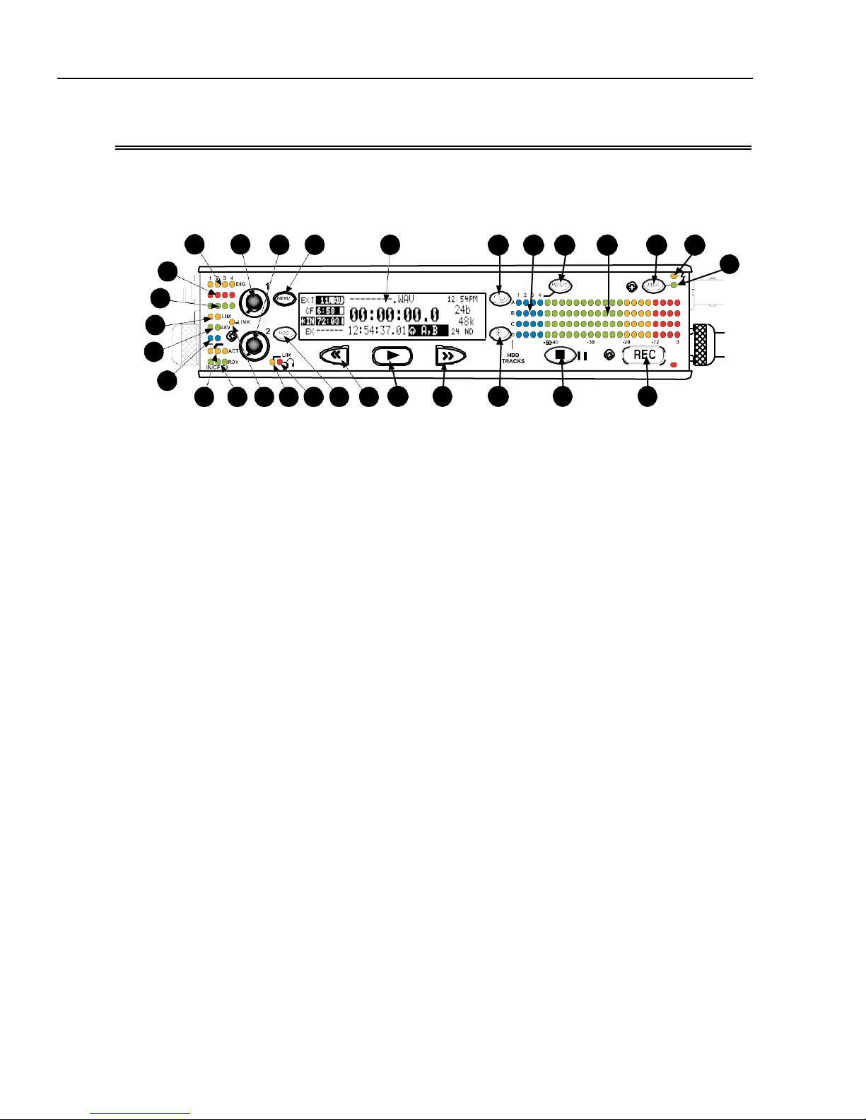
FrontPanelDescriptions
All 744T settings can be accessed and monitored th rough the front panel LCD and navigation keys.
This allows the unit to be placed in a production bag along with field mixers and wireless transmit-
ters and receivers.
744T
28
27
26
25
14 13
5) LCD Display
Primary display of 744T status. The
LCD is backlit using the LCDbacklight
control (#15).
24 23 22 21 20 19 18 17
1) DigitalInputLEDs
Indicates the presence of digital signal
on the respective input. When flashing,
indicates that digital input is selected
but no valid digital clock signal is pres-
ent.
29
5 6
1516
4
21 107 8 93
12
11
2) Input1Gain
Controls the analog gain (input trim) of
the channel 1 input. Normalmic input
range is from 25 dB to 70 dB, low gain
mic range is from 10 dB to 55 dB, line
input range is from −6 dB to 18 dB. For
line-level inputs, this control can be
defeated and gain can be setup menu-
controlled. If the LCD display shows
“locked” when the pot is turned, gain
control of the line-level input is menu-
controlled. When inputs arelinkedas
a stereo pair, Input 1 Gain controls the
gain of both inputs.
3) Input2Gain
Controls input 2 gain, as in #2 above.
When inputs are linkedas a stereo pair,
Input 2 Gain controls left-to-right bal-
ance.
4) MENU Key
Used to access all 744T setup menu
selections. When in menu mode, used to
move up through the menu selections.
Pressing the HDD andMENU keys
simultaneously brings up the time code
jam menu.
6) Tone Oscillator
Press to activate the tone oscillator, press
and hold for two seconds or longer to
latch on, press again to deactivate. Fre-
quency, tone level, and routing are con-
trolled in the Setup Menu. When inthe
Setup Menu use the TONE key to enter
Setup Menu options and select parame-
ters when the check mark appears inthe
upper right hand corner of the LCD.
7) Input-to-Track Matrix LEDs
Blue LEDs indicate inputs (1, 2, 3, 4)
enabled for recording to tracks (A, B, C,
D). A solid blue LEDindicates aninput
is routed to a track. A flashing LED dur-
ing “custom” routing mode shows the
selected input/track combination.
8) INPUTSelect Key
Pressing the INPUT key brings up the
input muting and routing menu. Hold
down the INPUT key and press one of
the four indicated soft keys to mute
inputs. Pressing theSTOP key and the
INPUT select key cycles through the
six factory preset input-to-track routing
combinations plus the custom routing
menu. In the custom routing menu any
input can be routed to any track. (See
Input-to-Track Routing)

9) Level MeterLEDs
Four, 19-segment track level-meters in-
dicate leve l in dBFS.Me t e ri ng ballistics
are selected in the setup menu.
10) PowerKey
Press and hold to power up the 744T.
Press and hold to power down.
11) ChargeLED
Indicates the charge status of the on-
board battery charger. LED flashes when
external power is connected and the re-
movable battery is charging; illuminates
solid when battery is fully charged.
12) PowerLED
Indicates the 744T is powered and avail-
able for operation. LED flashes when the
removable battery or external DC is in a
low-voltage state.
13) Record Key
Press to record. The 744T is a record-
priority device; pressing this key starts
recording and discontinues all other
functions, except file operations. Press-
ing key during recording can set a cue
marker or start a new file, as selected in
the setup menu.
14) Stop/Pause Key
Press and hold this key for 150 ms to
stop recording. In Record Pause mode
the STOP key will pause the recording,
pressing it twice will finalizethe record-
ing. In playback mode, a single press
pauses playback (play-pause), allowing
audio scrubbing with the FF and REW
keys. Another press of the k ey enters
play-stop mode where the FF and REW
keysselect files for playback from the
current directory. Onemore press of the
key exits playback mode. In the setup
menu the stop key is also used to exit
from any menu, returning to the main
display.
15) LCD Backlight Key
Press to toggle LCD and keyboard
backlighting. Hold the key andturn the
Rotary Switch to adjust the brightness of
LEDs. In menu mode, functions as the
cancel key.
16) Fast-Forward Key
Performs fast-forward (FF) scrubbing
through the playedfile when pressed in
playback and play-pause mode. Play-
pause indicated by flashing A-time on
LCD. Fast forward rate increases the lon-
ger the key is held. In play-stop mode
(indicated by flashing filename on LCD)
selects the next file in the record folder
(either daily folder or main folder).
17) Play Key
Plays back the file displayedin the LCD.
If pressed immediately after recording is
stopped, the most recently recorded file
is played back.
18) Rewind Key
Performs reverse (REW) scrubbing
through the playedfile when pressed in
playback and play-pause mode. Play-
pause indicated by flashing A-time on
LCD. Reverseplayback rate increases
the longer the key is held.In play-stop
mode (indicated by flashing filename
on LCD) selects the previous file in the
record folder (either daily folder or main
folder).
19) HDD (File Viewer) Key
Press to enter the File Viewer. The
selected medium shown in white type
will be the destination whenthe but-
ton is pressed. Press-and-hold to toggle
between available media. If only one
media is present, press-and-hold is
disabled. Pressing simultaneously with
MENU opens the time code jam menu.
20) HeadphoneOutputPeak LED
Indicates overload of the headphone
amplifier. When lit, the headphone cir-
cuit is overloading. Reduce headphone
level.
21) LIM LED
Indicates that the microphone input
limiters are engaged.This LED does not
show input limiting activity (see descrip-
tor #27, Microphone Input LimiterLEDs).
744T UserGuideand TechnicalInformation
22) Link LED
Indicates that channels 1 and 2 are
linked as a stereo pair. In linkmode in-
put 1 potentiometer controls gain, input
2 potentiometer controls left-to-right
balance. Inputs can be linked as either a
stereo L/R pair or as a a Mid-Side (MS)
pair.
23) Media Ready LEDs
Indicates storage media is present and
available to record; IN (internal hard
drive), CF (CompactFlash), EX(exter-
nal FireWire device). Flashing indicates
media problem.
24) Media ActivityLEDs
Indicates storage media read/write
activity. IN (internal hard drive), CF
(CompactFlash), EX (external FireWire
device).
25) High-Pass Filter LEDs
Indicates that the high-pass (low-cut)
filter is active for the input. High-pass
only operates when theinput is set to
microphone level.
26) Phantom Power LEDs
Indicates that phantom power (48 volts)
is active for the individual input. Phan-
tom can be applied to microphone or
line-level signals (menu-selected).
27) Microphone InputLimiterLEDs
Illuminates orange when limiting is oc-
curring on the microphone input. If con-
stantly lit, the microphone input is being
hit with too “hot” of a signal. Reducethe
input sensitivity untillimiting occurs
infrequently.
28) InputSignal PresenceLEDs
Indicates presence of analog or digital
signal and its relativelevel on each of
the four inputs.
29) InputPeak(Overload)LED
Indicates analog signal is approaching
clipping (–3 dBFS) on each of the four
inputs. Also used to indicate that an
input is muted.
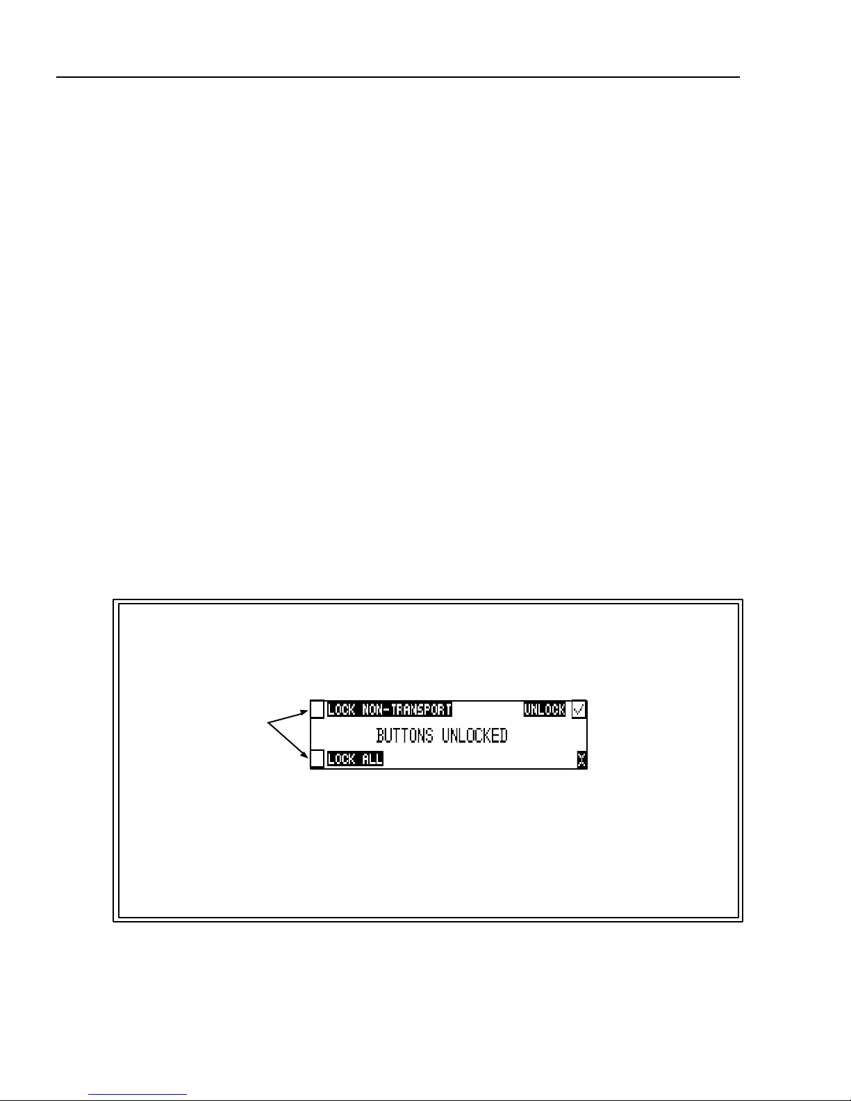
Panel Lock
Press and hold the backlight key then thetone key to bring up the front panel Button Lock Screen.
Button lock prevents unintentional changing of settings or record status.The 744T displays any but-
ton lock options enabled.
select the soft buttons to
activate theappropriate
button lock mode
There are three modes:
•Unlocked – all buttons are accessibleand operatenormally.
•Non-Transport Lock –Allfront panelcontrols are locked except the Record, Stop, Play, Re-
wind and Fast Forward.
•Lock All –All front panel keys are locked except the Record key. TheRecord key is kept ac-
tive so the user can initiate recording after entering this modeand enter cue markers. To stop
recording in this mode, you must disengage the panel lock and hit the stop key.
Other manuals for 552
3
Table of contents
Other Sound Devices Music Mixer manuals

Sound Devices
Sound Devices 633 User manual

Sound Devices
Sound Devices 664 Manual

Sound Devices
Sound Devices MixPre-10M User manual

Sound Devices
Sound Devices 664 User manual

Sound Devices
Sound Devices 552 Manual

Sound Devices
Sound Devices 633 Manual

Sound Devices
Sound Devices 664 User manual

Sound Devices
Sound Devices 664 Manual

Sound Devices
Sound Devices 633 User manual

Sound Devices
Sound Devices 664 Manual


