JEHNERT SOUND DESIGN 75151 User manual

SoundSound
D E S I G N
JEHNERT
AUDI A 4 Cabrio
Garantie
2003/by.AJ/FH - 15 -
Montageanleitung
Montageanl.Art. 75151/FH07.03
Artikel-Nr. 75151
Jehnert Sound Design
Entwicklung und
Produktion von
Car-Audio-Systemen
Heinrich-Hertz-Str. 11
70794 Filderstadt
Tel.: 0711-77 97 87- 87
Fax: 0711-77 78 921
www.jehnert.com
Als Hersteller übernehmen wir für diese Türpaneele bzw. Soundsystem eine
Garantie für 2 Jahre, gerechnet ab dem Kaufdatum beim Händler.
Innerhalb dieser Garantiezeit beheben wir nach unserer Wahl durch Reparatur
oder Austausch unentgeltlich alle Mängel, die auf Material- oder Herstellungs-
fehlern beruhen.
Von der Garantie ausgenommen sind Schäden, die auf unsachgemäßen Gebrauch,
auf Verschleiß oder auf Eingriffe durch Dritte zurückzuführen sind. Die Garantie
umfasst keine Folgeschäden und auch nicht diejenigen Mängel, die den
Wert oder die Gebrauchstauglichkeit der Paneele / Soundsystem nur unerheblich
beeinträchtigen. Eine Garantiepflicht wird nicht ausgelöst bei Schäden die durch
äußere Einwirkungen verursacht wurden.
Vom Umtausch ausgeschlossen sind Paneele mit zusätzlichen oder falschen
Montagebohrlöcher. Dies sind Beschädigungen am Paneel, die nicht wieder
Instand gesetzt werden können.
�
installation instruction
convertible
prod. code
Production of
Car-Audio-Systems
Porsche Str. 15
70794 Filderstadt
Tel. 00 49 71 58 / 9 56 99-0
Fax 00 49 71 58 / 9 56 99-10
e-mail: [email protected]
www.jehnert.com

Packliste ..............................................................................
1. Demontage der Türverkleidung...............................................
2. Montage des Hochtöners .......................................................
3. Paneelanpassung ..................................................................
4. Bearbeiten der Türverkleidung / Montage der Türpaneele..........
5. Frequenzweichenmontage + Lautsprecherleitungen .................
6. Dämmung der Türverkleidung / Fahrzeugtüren ........................
7. Montage der Türverkleidung ..................................................
8. Lautsprecheranschluss ..........................................................
Lautsprecheranschluss - Schaltbild ........................................
9. Montage der Lautsprecher-Abdeckblenden .............................
Technische Informationen .....................................................
Service / Fehlersuche............................................................
Garantie .............................................................................
Steffen Kretzschmar
Sattlerei / Produktionsablauf
Durchwahl: - 69
Seite
2
3
4
5
6
7
8
9
10
11
12
13
14
15
75151 - Audi A 4 Cabrio - 14 - © JEHNERT SOUND DESIGN75151 - Audi A 4 Cabrio - 1 - © JEHNERT SOUND DESIGN
Technische Fragen: Info-Hotline: 0711 - 77 97 87 - 87
Wir danken für Ihre Unterstützung !
Mirko Schwarz
Produktentwicklung / Qualität
Durchwahl: - 67
Wir helfen Ihnen gerne weiter!
Sehr geehrter Kunde,
Wir haben uns sehr bemüht unsere neuen Montageanleitungen ausführlicher und
“Schritt für Schritt”zu erklären.
Ihre Tipps und Anregungen helfen uns künftige Unklarheiten oder Fehlinter-
pretationen weiter auszuschließen.
Teilen Sie uns deshalb mit, was Ihnen nicht gefällt oder was wir noch ändern sollten.
Marc Sitter
Versand / Service
Durchwahl: - 68
Marc Sitter
Versand / Service
Durchwahl: - 68
Die folgenden Hinweise sollen Ihnen dabei helfen, Fehler oder Störungen selbst zu
beheben. Wenn folgende Abhilfemaßnahmen nicht greifen, rufen Sie uns bitte an:
Was kann es sein ... mögliche Ursache / Lösung
wenn’s nicht richtig klingt Tieftöner verpolt ( Seite 10)
Frequenzweichen falsch angeschlossen ( Seite 11)
Türverkleidung und Regenschutzfolie
nicht ausgeschnitten ( Seite 7+9)
Verstärker zu wenig Leistung ( Seite 13)
Verstärker-Anschluss
wenn’s nicht richtig passt Fixpunkte Türpaneelanpassung ( Seite 6)
Montage der Paneele auf die TV ( Seite 7)
Abdeckungen nicht haften Hinweise Seite 12 beachten!
Vibrationsgeräusche Dämmung s. Hinweise Seite 8
Selbsthilfe und Fehlersuche
Inhaltsverzeichnis
Besonders wichtige Hinweise enthalten folgende Markierung:
�
Bitte folgen Sie den Anweisungen der Montageanleitung
“Schritt für Schritt”
und prüfen Sie den Packungsinhalt
Packing list .......................................................................... 2
1. Disassembly of the door lining .............................................. 3
2. Installation midrange and tweeter in the dashboard ................ 4
3. Panel alignment ................................................................... 5
4. Handling of doorlining / Installation door panel ..................... 6
5. speaker cables / Handling of car doors .................................. 7
6. Insulation of the door lining / car doors ................................. 8
7. Installation of the door lining onto the car doors .................... 9
8. Crossover circuit - Speaker connection .................................. 10
Lodspeaker wiring diagram .................................................. 11
9. Installation of the speaker-grills ............................................ 12
Technical Information .......................................................... 13
Service / fault diagnoses ....................................................... 14
Guarantee .......................................................................... 15
page
75110 VW Bus T 4 - 1 - © JEHNERT SOUND DESIGN
Contents
Particularly important notes contain the following remarks:
Please follow the installation instructions
“step by step”
and check the package contents
Steffen Kretzschmar
Saddlery / Completion
75110 VW Bus T 4 - 14 - © JEHNERT SOUND DESIGN
Technical questions Hotline: 0049-711-77 97 87-87
We thank you for your support!
Mirko Schwarz
Development
It is our pleasure to help you!
Dear customer,
We have taken great care to explain the procedures in our installation instructions
more detailed and “step by step”.
Your tips and suggestions help us for the future to eliminate uncertainties and
misinterpretation. Therefore, please inform us. what you would like to be improved
or what we should still change.
Marc Sitter
Export / Service
Marc Sitter
Export / Service
The following notes serve to help troubleshoot and eliminate faults or malfunctions
on your own. If the following measures are not effective, please call us.
What can it be if ... possible cause/ solution
..it doesn’t sound right. wrong polarity on the subwoofers ( page 10)
crosover circuit attached wrong ( page 11)
Doorlining and moisture protection foil
not cut out ( page 6+9)
amplifier doesn’t have enough power ( page 13)
amplifier connection
...it doesn’t fit correctly. door panel customization ( page 5)
installation of the panels on the door lining (page 6)
.....grills do not hold. observe notes on page 12!
vibrations insulation, see notes on page 8
Self-help and fault diagnosis
Technical questions: Hotline 00 49 71 58 / 9 56 99-0

Verpackungseinheit Checkliste
Türpaneele, bezogen (rechts / links) 2
Abdeck-Blenden, bezogen (rechts / links) 4
Hochtöner 26 mm 2
Mitteltöner 100 mm Q (jeweils mit 2 Blechschrauben am Paneel montiert) 2
Tieftöner 160 mm (jeweils mit 2 Blechschrauben am Paneel montiert) 8
Frequenzweichen (rechts / links) 2
serieller Kabelsatz für Tieftöner (rechts / links) je 1
Kleinteile-Beutel:
Schrauben-Senkkopf, M 4 x 20 4
Schrauben-Senkkopf, M 4 x 30 6
6-Ktn.Mutter M 4 22
Unterlagscheiben Ø20mm 22
Unterlagscheiben Ø20mm als Distanzhilfe für Klettverschlüsse 4
Blechschrauben, schwarz 3,9x13(f. Tieftöner) 8
Klettband à2,5 cm (Reserve) 4
Kleinteile-bereits montiert:
Klettverschlüsse + Klettband 16
Schrauben-Senkkopf, M 4 x 20 2
Schrauben-Senkkopf, M 4 x 30 2
Schrauben-Senkkopf, M 4 x 40 2
Schrauben-Senkkopf, M 4 x 50 4
Blechschrauben, schwarz 3,9 x 13 (für Tieftöner) 8
Blechschrauben, schwarz 3,5 x 13 (4xMT+16xKlettv.) 20
Die Ware wurde sorgfältig verpackt und auf ihre Vollständigkeit geprüft. Bei Fehlmengen, Schäden oder Mängel
beachten Sie bitte unsere Garantieleistungen auf der Rückseite dieser Montageanleitung.
Kleinteile-Beutel:
Packliste Art. 75151
75151 - Audi A 4 Cabrio - 13 - © JEHNERT SOUND DESIGN 75151 - Audi A 4 Cabrio - 2 - © JEHNERT SOUND DESIGN
Technische Information
Fahrzeugausstattung: elektrische Fensterheber
Modell/ Modelljahr: A4 Cabrio
Dämmung der Türen: empfohlen
Einstell-Hinweis: Um den optimalen Raumklang zu erzielen,
sollten am Radiogerät sämtliche Einstellungen
(Bass, Höhen, Loudness usw.) auf Null bzw.
neutral eingestellt werden
empfohlene
Verstärkerleistung: ab 2x 200 - 360 Watt sinus / 4 Ohm
Blechschneidearbeiten: entfallen
Lautsprecherausschnitte/ 4 x 144mm (max.AußenmaßTieftöner 165 mm)
pro Seite (max.Einbautiefe Tieftöner 65 mm)
Euro-Norm-Korb passend
1 x 92mm (max.AußenmaßMitteltöner 100 mm)
(max.Einbautiefe Mitteltöner 55 mm)
Sound-System: 3-Wege
4 x 160 mm Tieftöner / Seite
1 x 100 mm Mitteltöner / Seite
1 x 26 mm Hochtöner / Seite
fahrzeugspezifische Frequenzweiche
Belastbarkeit Dauer / Musik: 2 x 300/500Watt
Übertragungsbereich: 49-22.000 Hz
Impedanz: 4 Ohm
Einbauzeit: Einbauprofi: 3-4 Stunden
Änderungen, die dem technischen Fortschritt dienen, bleiben vorbehalten.
Packing unit Check list
door panel, covered (right / left) 2
Speaker grill, covered (right / left) 2
Tweeter 26 mm (with perforated sheet metal,6.Ktn.Screw M4x8,Washer ø 12mm) 2
Midrange 100 mm Q (each mounted on the panel with 4 Sheet metal-screws) 2
Woofer 160 mm (each mounted on the panel with 2 Sheet metal-screws) 8
Crossover (right / left) 2
standard cables for subwoofer (right / left) 2
Hardware bag:
Hexagon head screws, M 4 x 30 6
Hexagon head screws, M 4 x 40 4
Hexagon head screws, M 4 x 50 6
Spax screws 5,0 x 70 4
Spax screws 5,0 x 80 2
Hex nut M 4 16
Washer Ø 20mm (incl. 4x as spacer for Velcro fastener)18
Washer Ø 12mm 8
Sheet metal screws, black 3,9x13 (f. woofer) 16
Velcro strip à 2,5 cm (reserve) 4
Preassembled hardware:
Velcro fastener plus strips 14
Sheet metal screws, black 3,9 x 13 (f. woofer) 16
Sheet metal screws, black 3,5 x 13 (f. midrange) 8
Sheet metal screws, black 3,5 x 13 (f. Velcro fastener) 14
The product was carefully packed and checked for its completeness. If you find anything missing, damaged or
defective, please notice our guarantee services on the back of these assembly instructions.
Hardware bag:
Packing list 75149
75149 - BMW Z 3 - 13 - © JEHNERT SOUND DESIGN 75149 - BMW Z 3 - 2 - © JEHNERT SOUND DESIGN
Technical information
Equipment: electric window control
Model/ year : Roadster / Coupé / M3
Insulation:
is absolutely necessary !
Note about setting: To obtain optimal stereoscopic sound, all settings
on the radio (bass, treble, loudness etc) should be
set to zero or neutral.
Recommended
amplifier power : from 2x 200 - 360 Watt RMS / 4 Ohm
Metal cutwork : not necessary
Cut-outs for loudspeaker/ 4 x 144mm (max.outer dimensions subwoofer 165 mm)
each side (max.installation depth subwoofer 65 mm)
DIN-Euro-Norm-standard basket ø6“made it fit
1 x 92mm (max.outer dimensions midrange 100 mm)
(max.installation depth midrange 50 mm)
Sound-System: 3-ways
4 x 160 mm subwoofer/ side
1 x 100 mm midrange / side
1 x 26 mm tweeter / side
car-customized crossover network
max.continuous Watt/RMS: 2 x 300/500Watt
car specific frequency range: 49-22.000 Hz
Total impedance: 4 Ohm
Time for Installation car hifi-specialist: 3,5 hours
We reserve the right to make technical changes, as well as development.
(with perforated sheet metal, hex nut M4, washer Ø 12 mm)
4
165
4
Packing unit Check list
door panel, covered (right / left) 2
Speaker grill, covered (right / left) 2
Tweeter 26 mm (with perforated sheet metal,6.Ktn.Screw M4x8,Washer ø 12mm) 2
Midrange 100 mm Q (each mounted on the panel with 4 Sheet metal-screws) 2
Woofer 160 mm (each mounted on the panel with 2 Sheet metal-screws) 8
Crossover (right / left) 2
standard cables for subwoofer (right / left) 2
Hardware bag:
Hexagon head screws, M 4 x 30 6
Hexagon head screws, M 4 x 40 4
Hexagon head screws, M 4 x 50 6
Spax screws 5,0 x 70 4
Spax screws 5,0 x 80 2
Hex nut M 4 16
Washer Ø 20mm (incl. 4x as spacer for Velcro fastener)18
Washer Ø 12mm 8
Sheet metal screws, black 3,9x13 (f. woofer) 16
Velcro strip à 2,5 cm (reserve) 4
Preassembled hardware:
Velcro fastener plus strips 14
Sheet metal screws, black 3,9 x 13 (f. woofer) 16
Sheet metal screws, black 3,5 x 13 (f. midrange) 8
Sheet metal screws, black 3,5 x 13 (f. Velcro fastener) 14
The product was carefully packed and checked for its completeness. If you find anything missing, damaged or
defective, please notice our guarantee services on the back of these assembly instructions.
Hardware bag:
Packing list 75149
75149 - BMW Z 3 - 13 - © JEHNERT SOUND DESIGN 75149 - BMW Z 3 - 2 - © JEHNERT SOUND DESIGN
Technical information
Equipment: electric window control
Model/ year : Roadster / Coupé / M3
Insulation:
is absolutely necessary !
Note about setting: To obtain optimal stereoscopic sound, all settings
on the radio (bass, treble, loudness etc) should be
set to zero or neutral.
Recommended
amplifier power : from 2x 200 - 360 Watt RMS / 4 Ohm
Metal cutwork : not necessary
Cut-outs for loudspeaker/ 4 x 144mm (max.outer dimensions subwoofer 165 mm)
each side (max.installation depth subwoofer 65 mm)
DIN-Euro-Norm-standard basket ø6“made it fit
1 x 92mm (max.outer dimensions midrange 100 mm)
(max.installation depth midrange 50 mm)
Sound-System: 3-ways
4 x 160 mm subwoofer/ side
1 x 100 mm midrange / side
1 x 26 mm tweeter / side
car-customized crossover network
max.continuous Watt/RMS: 2 x 300/500Watt
car specific frequency range: 49-22.000 Hz
Total impedance: 4 Ohm
Time for Installation car hifi-specialist: 3,5 hours
We reserve the right to make technical changes, as well as development.
Packing unit Check list
door panel, covered (right / left) 2
Speaker grill, covered (right / left) 2
Tweeter 26 mm (with perforated sheet metal,6.Ktn.Screw M4x8,Washer ø 12mm) 2
Midrange 100 mm Q (each mounted on the panel with 4 Sheet metal-screws) 2
Woofer 160 mm (each mounted on the panel with 2 Sheet metal-screws) 8
Crossover (right / left) 2
standard cables for subwoofer (right / left) 2
Hardware bag:
Hexagon head screws, M 4 x 30 6
Hexagon head screws, M 4 x 40 4
Hexagon head screws, M 4 x 50 6
Spax screws 5,0 x 70 4
Spax screws 5,0 x 80 2
Hex nut M 4 16
Washer Ø 20mm (incl. 4x as spacer for Velcro fastener)18
Washer Ø 12mm 8
Sheet metal screws, black 3,9x13 (f. woofer) 16
Velcro strip à 2,5 cm (reserve) 4
Preassembled hardware:
Velcro fastener plus strips 14
Sheet metal screws, black 3,9 x 13 (f. woofer) 16
Sheet metal screws, black 3,5 x 13 (f. midrange) 8
Sheet metal screws, black 3,5 x 13 (f. Velcro fastener) 14
The product was carefully packed and checked for its completeness. If you find anything missing, damaged or
defective, please notice our guarantee services on the back of these assembly instructions.
Hardware bag:
Packing list 75149
75149 - BMW Z 3 - 13 - © JEHNERT SOUND DESIGN 75149 - BMW Z 3 - 2 - © JEHNERT SOUND DESIGN
Technical information
Equipment: electric window control
Model/ year : Roadster / Coupé / M3
Insulation:
is absolutely necessary !
Note about setting: To obtain optimal stereoscopic sound, all settings
on the radio (bass, treble, loudness etc) should be
set to zero or neutral.
Recommended
amplifier power : from 2x 200 - 360 Watt RMS / 4 Ohm
Metal cutwork : not necessary
Cut-outs for loudspeaker/ 4 x 144mm (max.outer dimensions subwoofer 165 mm)
each side (max.installation depth subwoofer 65 mm)
DIN-Euro-Norm-standard basket ø6“made it fit
1 x 92mm (max.outer dimensions midrange 100 mm)
(max.installation depth midrange 50 mm)
Sound-System: 3-ways
4 x 160 mm subwoofer/ side
1 x 100 mm midrange / side
1 x 26 mm tweeter / side
car-customized crossover network
max.continuous Watt/RMS: 2 x 300/500Watt
car specific frequency range: 49-22.000 Hz
Total impedance: 4 Ohm
Time for Installation car hifi-specialist: 3,5 hours
We reserve the right to make technical changes, as well as development.
20
Packing unit Check list
door panel, covered (right / left) 2
Speaker grill, covered (right / left) 2
Tweeter 26 mm (with perforated sheet metal,6.Ktn.Screw M4x8,Washer ø 12mm) 2
Midrange 100 mm Q (each mounted on the panel with 4 Sheet metal-screws) 2
Woofer 160 mm (each mounted on the panel with 2 Sheet metal-screws) 8
Crossover (right / left) 2
standard cables for subwoofer (right / left) 2
Hardware bag:
Hexagon head screws, M 4 x 30 6
Hexagon head screws, M 4 x 40 4
Hexagon head screws, M 4 x 50 6
Spax screws 5,0 x 70 4
Spax screws 5,0 x 80 2
Hex nut M 4 16
Washer Ø 20mm (incl. 4x as spacer for Velcro fastener)18
Washer Ø 12mm 8
Sheet metal screws, black 3,9x13 (f. woofer) 16
Velcro strip à 2,5 cm (reserve) 4
Preassembled hardware:
Velcro fastener plus strips 14
Sheet metal screws, black 3,9 x 13 (f. woofer) 16
Sheet metal screws, black 3,5 x 13 (f. midrange) 8
Sheet metal screws, black 3,5 x 13 (f. Velcro fastener) 14
The product was carefully packed and checked for its completeness. If you find anything missing, damaged or
defective, please notice our guarantee services on the back of these assembly instructions.
Hardware bag:
Packing list 75149
75149 - BMW Z 3 - 13 - © JEHNERT SOUND DESIGN 75149 - BMW Z 3 - 2 - © JEHNERT SOUND DESIGN
Technical information
Equipment: electric window control
Model/ year : Roadster / Coupé / M3
Insulation:
is absolutely necessary !
Note about setting: To obtain optimal stereoscopic sound, all settings
on the radio (bass, treble, loudness etc) should be
set to zero or neutral.
Recommended
amplifier power : from 2x 200 - 360 Watt RMS / 4 Ohm
Metal cutwork : not necessary
Cut-outs for loudspeaker/ 4 x 144mm (max.outer dimensions subwoofer 165 mm)
each side (max.installation depth subwoofer 65 mm)
DIN-Euro-Norm-standard basket ø6“made it fit
1 x 92mm (max.outer dimensions midrange 100 mm)
(max.installation depth midrange 50 mm)
Sound-System: 3-ways
4 x 160 mm subwoofer/ side
1 x 100 mm midrange / side
1 x 26 mm tweeter / side
car-customized crossover network
max.continuous Watt/RMS: 2 x 300/500Watt
car specific frequency range: 49-22.000 Hz
Total impedance: 4 Ohm
Time for Installation car hifi-specialist: 3,5 hours
We reserve the right to make technical changes, as well as development.
Packing unit Check list
door panel, covered (right / left) 2
Speaker grill, covered (right / left) 2
Tweeter 26 mm (with perforated sheet metal,6.Ktn.Screw M4x8,Washer ø 12mm) 2
Midrange 100 mm Q (each mounted on the panel with 4 Sheet metal-screws) 2
Woofer 160 mm (each mounted on the panel with 2 Sheet metal-screws) 8
Crossover (right / left) 2
standard cables for subwoofer (right / left) 2
Hardware bag:
Hexagon head screws, M 4 x 30 6
Hexagon head screws, M 4 x 40 4
Hexagon head screws, M 4 x 50 6
Spax screws 5,0 x 70 4
Spax screws 5,0 x 80 2
Hex nut M 4 16
Washer Ø 20mm (incl. 4x as spacer for Velcro fastener)18
Washer Ø 12mm 8
Sheet metal screws, black 3,9x13 (f. woofer) 16
Velcro strip à 2,5 cm (reserve) 4
Preassembled hardware:
Velcro fastener plus strips 14
Sheet metal screws, black 3,9 x 13 (f. woofer) 16
Sheet metal screws, black 3,5 x 13 (f. midrange) 8
Sheet metal screws, black 3,5 x 13 (f. Velcro fastener) 14
The product was carefully packed and checked for its completeness. If you find anything missing, damaged or
defective, please notice our guarantee services on the back of these assembly instructions.
Hardware bag:
Packing list 75149
75149 - BMW Z 3 - 13 - © JEHNERT SOUND DESIGN 75149 - BMW Z 3 - 2 - © JEHNERT SOUND DESIGN
Technical information
Equipment: electric window control
Model/ year : Roadster / Coupé / M3
Insulation:
is absolutely necessary !
Note about setting: To obtain optimal stereoscopic sound, all settings
on the radio (bass, treble, loudness etc) should be
set to zero or neutral.
Recommended
amplifier power : from 2x 200 - 360 Watt RMS / 4 Ohm
Metal cutwork : not necessary
Cut-outs for loudspeaker/ 4 x 144mm (max.outer dimensions subwoofer 165 mm)
each side (max.installation depth subwoofer 65 mm)
DIN-Euro-Norm-standard basket ø6“made it fit
1 x 92mm (max.outer dimensions midrange 100 mm)
(max.installation depth midrange 50 mm)
Sound-System: 3-ways
4 x 160 mm subwoofer/ side
1 x 100 mm midrange / side
1 x 26 mm tweeter / side
car-customized crossover network
max.continuous Watt/RMS: 2 x 300/500Watt
car specific frequency range: 49-22.000 Hz
Total impedance: 4 Ohm
Time for Installation car hifi-specialist: 3,5 hours
We reserve the right to make technical changes, as well as development.
26
Packing unit Check list
door panel, covered (right / left) 2
Speaker grill, covered (right / left) 2
Tweeter 26 mm (with perforated sheet metal,6.Ktn.Screw M4x8,Washer ø 12mm) 2
Midrange 100 mm Q (each mounted on the panel with 4 Sheet metal-screws) 2
Woofer 160 mm (each mounted on the panel with 2 Sheet metal-screws) 8
Crossover (right / left) 2
standard cables for subwoofer (right / left) 2
Hardware bag:
Hexagon head screws, M 4 x 30 6
Hexagon head screws, M 4 x 40 4
Hexagon head screws, M 4 x 50 6
Spax screws 5,0 x 70 4
Spax screws 5,0 x 80 2
Hex nut M 4 16
Washer Ø 20mm (incl. 4x as spacer for Velcro fastener)18
Washer Ø 12mm 8
Sheet metal screws, black 3,9x13 (f. woofer) 16
Velcro strip à 2,5 cm (reserve) 4
Preassembled hardware:
Velcro fastener plus strips 14
Sheet metal screws, black 3,9 x 13 (f. woofer) 16
Sheet metal screws, black 3,5 x 13 (f. midrange) 8
Sheet metal screws, black 3,5 x 13 (f. Velcro fastener) 14
The product was carefully packed and checked for its completeness. If you find anything missing, damaged or
defective, please notice our guarantee services on the back of these assembly instructions.
Hardware bag:
Packing list 75149
75149 - BMW Z 3 - 13 - © JEHNERT SOUND DESIGN 75149 - BMW Z 3 - 2 - © JEHNERT SOUND DESIGN
Technical information
Equipment: electric window control
Model/ year : Roadster / Coupé / M3
Insulation:
is absolutely necessary !
Note about setting: To obtain optimal stereoscopic sound, all settings
on the radio (bass, treble, loudness etc) should be
set to zero or neutral.
Recommended
amplifier power : from 2x 200 - 360 Watt RMS / 4 Ohm
Metal cutwork : not necessary
Cut-outs for loudspeaker/ 4 x 144mm (max.outer dimensions subwoofer 165 mm)
each side (max.installation depth subwoofer 65 mm)
DIN-Euro-Norm-standard basket ø6“made it fit
1 x 92mm (max.outer dimensions midrange 100 mm)
(max.installation depth midrange 50 mm)
Sound-System: 3-ways
4 x 160 mm subwoofer/ side
1 x 100 mm midrange / side
1 x 26 mm tweeter / side
car-customized crossover network
max.continuous Watt/RMS: 2 x 300/500Watt
car specific frequency range: 49-22.000 Hz
Total impedance: 4 Ohm
Time for Installation car hifi-specialist: 3,5 hours
We reserve the right to make technical changes, as well as development.
8
Packing unit Check list
door panel, covered (right / left) 2
Speaker grill, covered (right / left) 2
Tweeter 26 mm (with perforated sheet metal,6.Ktn.Screw M4x8,Washer ø 12mm) 2
Midrange 100 mm Q (each mounted on the panel with 4 Sheet metal-screws) 2
Woofer 160 mm (each mounted on the panel with 2 Sheet metal-screws) 8
Crossover (right / left) 2
standard cables for subwoofer (right / left) 2
Hardware bag:
Hexagon head screws, M 4 x 30 6
Hexagon head screws, M 4 x 40 4
Hexagon head screws, M 4 x 50 6
Spax screws 5,0 x 70 4
Spax screws 5,0 x 80 2
Hex nut M 4 16
Washer Ø 20mm (incl. 4x as spacer for Velcro fastener)18
Washer Ø 12mm 8
Sheet metal screws, black 3,9x13 (f. woofer) 16
Velcro strip à 2,5 cm (reserve) 4
Preassembled hardware:
Velcro fastener plus strips 14
Sheet metal screws, black 3,9 x 13 (f. woofer) 16
Sheet metal screws, black 3,5 x 13 (f. midrange) 8
Sheet metal screws, black 3,5 x 13 (f. Velcro fastener) 14
The product was carefully packed and checked for its completeness. If you find anything missing, damaged or
defective, please notice our guarantee services on the back of these assembly instructions.
Hardware bag:
Packing list 75149
75149 - BMW Z 3 - 13 - © JEHNERT SOUND DESIGN 75149 - BMW Z 3 - 2 - © JEHNERT SOUND DESIGN
Technical information
Equipment: electric window control
Model/ year : Roadster / Coupé / M3
Insulation:
is absolutely necessary !
Note about setting: To obtain optimal stereoscopic sound, all settings
on the radio (bass, treble, loudness etc) should be
set to zero or neutral.
Recommended
amplifier power : from 2x 200 - 360 Watt RMS / 4 Ohm
Metal cutwork : not necessary
Cut-outs for loudspeaker/ 4 x 144mm (max.outer dimensions subwoofer 165 mm)
each side (max.installation depth subwoofer 65 mm)
DIN-Euro-Norm-standard basket ø6“made it fit
1 x 92mm (max.outer dimensions midrange 100 mm)
(max.installation depth midrange 50 mm)
Sound-System: 3-ways
4 x 160 mm subwoofer/ side
1 x 100 mm midrange / side
1 x 26 mm tweeter / side
car-customized crossover network
max.continuous Watt/RMS: 2 x 300/500Watt
car specific frequency range: 49-22.000 Hz
Total impedance: 4 Ohm
Time for Installation car hifi-specialist: 3,5 hours
We reserve the right to make technical changes, as well as development.

1.5. Torx-Schraube (D) unter der Abdeckung der Schalterleiste/Fahrerseite
bzw. Fensterheberschalter/Beifahrerseite entfernen.
1.6. Schraube (E) am unteren Türverkleidungsrand entfernen.
1.7. Türverkleidung vorsichtig nach vorne abnehmen und nach oben wegziehen.
1.8. Türentriegelungsbowdenzug aushängen.
1.9. Elektrischen Anschlußfür Schaltleiste abstecken.
1.10. Original-Lautsprecheranschluss abstecken und werkseitiger Tieftöner demontieren.
1.11. Werkseitiges Kartenfach und Original-Lautsprecher entfernen:
Befestigungsnieten gebm. Abb. auf der Türverkleidungs-Rückseite abhebeln und
komplette Einheit abnehmen.
Abnehmen der Abdeckblenden:
Die Abdeckblenden können durch vorsichtiges Lösen der Klettverschlüsse
jederzeit abgenommen werden.
VORSICHT:
Bitte jede Art von »gewaltsamem Reißen «an den Blenden
vermeiden (Bruchgefahr !)
Abb.: Türverkleidungsrückseite- Demontage werkseitiges Kartenfach
1 . Demontage der Türverkleidung
75151 - Audi A 4 Cabrio - 12 - © JEHNERT SOUND DESIGN75151 - Audi A 4 Cabrio - 3 - © JEHNERT SOUND DESIGN
Die Klettverschlüsse sind ab Werk bereits komplett auf den Abdeckblenden
montiert.
WICHTIG :
Die Klettverschlüsse haften sehr stark!
Die Abdeckblenden deshalb erst nach kompletter Montage der Türpaneele
und Soundsystem fest aufdrücken !
Tipp:
... wenn sich die Abdeckblende an manchen Stellen nicht auf dem
Paneel festdrücken läßt ...
Ursache: Die besondere Formgebung der Türpaneele an dieser Stelle
und die daraus resultierende unterschiedliche Materialstärken
der Abdeckblenden.
Lösung: Mit einer M 4-Unterlagscheibe ø20mm (3) unter dem
Klett-Teller wird dieser Abstand einfach und schnell ausgeglichen:
9. Montage der Abdeckblenden :
�
�
�
Abdeckblende
2 selbstklebendes Klettband
1 Klett-Druckverschluss
3 Unterlagscheibe M4 ø20 als Distanzhilfe
Türpaneel
B
A
1.1. Fensterscheibe komplett herunterlassen.
1.3. Darunterliegende 4 Schrauben (B1+2: Torxschr. / B3+4: Kreuzkopfschr.) entfernen.
D
1.2. Demontage der Holzleiste
(am Fixpunkt A beginnend!)
•Seitenkanten (Abb. A+B) mit
einem Keil vorsichtig nach vorne
abdrücken.
•in Richtung Türschloss schieben
und abziehen.
1.4. Die Abdeckung der Schalter-
leiste/Fahrerseite und Fenster-
heberschalter/Beifahrerseite
durch die Öffnung unterhalb
des Türgriffes herausdrücken.
E
D
C1C2
C3C4
Roll down window completely.1.1.
Remove the Bowden pull wire of the door latch lever.1.8.
Disconnect the original loudspeaker plugs and dismount the original speaker.1.10.
1. Disassembly of the door lining
Disassambly of the wooden ledge
(start on xing point A!)
• Carefully squeeze away the side
edges ( see g. A+B) with a key.
• Move it in direction of the
door lock and lift it off.
1.2.
Disassambly of the wooden ledge
(start on xing point A!)
• Carefully squeeze away the side
edges ( see g. A+B) with a key.
• Move it in direction of the
door lock and lift it off.
1.4.
Remove the 4 screws (B1+2 torx screw, B3+4 crosshead screw).1.3.
Remove the torx screw (D) under the grill of the switch board / driver’s side,
respectively the switch for the window lifter / co-driver’s side.
1.5.
Remove the screw (E) on the lower edge of the door card.1.6.
Carefully take the door card forward away and pull it upward away.1.7.
Unplug the switch board.1.9.
Remove the original tray and the original speakers: pry out the rivets on the
backside of the door card and take away the whole unit (see g.).
1.11.
g.: disassembly original tray – backside of the door card

Lautsprecheranschluss - Schaltbild
Alle Lautsprecher und Frequenzweichen anschließen:
H
i
g
h
P
e
r
f
o
r
m
a
n
c
e
D E S I G N
JEHNERT
SoundSound
Midrange
Speaker
MADE INGERMANY
2.1. Plastikrahmen des Hochton-Gitters mit einem Keil ausklipsen und
abnehmen.
2.2. Werkseitiger Hochtöner entfernen und Lautsprecher-Anschlußabstecken.
2.3. JEHNERT-Hochtöner mit Lautsprecherkabel (1,5 - 4mm ) verkabeln
Kabellänge: bis zur Frequenzweiche
Montage unterhalb des Armaturenbrettes
2.4. Das Langlochblech am Hochtöner mittels Unterlagscheibe und 6Ktn.
Schraube befestigen.
2.5. Hochtöner mit dem Langlochblech in die werkseitige Einbauöffnung
einsetzen, Lautsprecherkabel zum Frequenzweichen-Montageort führen,
Langlochblech befestigen.
.
Akustische Empfehlung:
Hochtöner angewinkelt zum Innen-Rückspiegel justieren.
(Nicht zur Fahrer - oder Beifahrerseite!)
H
i
g
h
P
e
r
f
o
r
m
a
n
c
e
DE S I G N
JEHNERT
SoundSound
Tweeter
Speaker
MADE INGERMANY
75151 - Audi A 4 Cabrio - 11 - © JEHNERT SOUND DESIGN 75151 - Audi A 4 Cabrio - 4 - © JEHNERT SOUND DESIGN
Schaltbild 3-Wege Frequenzweiche / 4x Tieftöner
H
i
g
h
P
e
r
f
o
r
m
a
n
c
e
D E S I G N
JEHNERT
SoundSound
WOOFER
Speaker
MADE IN GERMANY
H
i
g
h
P
e
r
f
o
r
m
a
n
c
e
D E S I G N
JEHNERT
SoundSound
WOOFER
Speaker
MADE IN GERMANY
H
i
g
h
P
e
r
f
o
r
m
a
n
c
e
D E S I G N
JEHNERT
SoundSound
WOOFER
Speaker
MADE IN GERMANY
H
i
g
h
P
e
r
f
o
r
m
a
n
c
e
D E S I G N
JEHNERT
SoundSound
WOOFER
Speaker
MADE IN GERMANY
2 . Montage des Hochtöners im Armaturenbrett
�
HochtönerTieftöner
SoundSound
D E S I G N
JEHNERT
MitteltönerEingang
3-Wege fahrzeugspezifische Frequenzweiche
Audi A 4 Cabrio - 75151
= mitgelieferter Kabelstrang
Verstärker
ab 200 Watt RMS / 4 Ohm
empf.Leistung
Acoustic recommendation:
Adjust the tweeter in an angular position to the inner review
mirror --> not in direction of the driver‘s or co-driver‘s side!
Dismount the original speaker grill and the tweeter in the original
mount of the dashboard. Unplug the cable (original tweeter and cable
will not be used any more).
2.1.
Adapt the JEHNERT-tweeter cable with the speaker cable (1,5 - 4 qmm),
length of cable up to where the crossover is installed under the dash-
board.
2.2.
2. Tweeter installation in the dashboard
Afx the perforated sheet with washer and hexagon screw on the
tweeter.
2.3.
Insert the tweeter with perforated sheet in the original place, lead the
speaker cable to the mounting position of the crossover and afx the
perforated sheet.
2.4.

8. Frequenzweichenmontage und Lautsprecheranschluss
5.1.1 Frequenzweichen vorverkabeln - vgl. Abb. Seite 11.
5.2.1 Gehäuse entfernen und hinter dem Steg des Türpaneels zwischen
Türverkleidung und Türpaneel einschieben und sicheren Sitz
befestigen.
Tief- und Mitteltöner einsetzen und alle Lautsprecher mit der
Frequenzweiche verkabeln (Paralell-Schaltung):
Hinweis: Bevor alle Tieftöner an die Frequenzweiche angeschlossen werden,
sollte die Polarität aller Tieftöner an einer 9 Volt-Batterie
überprüft werden:
Pol des FW-Eingang an von 9 V Batterie
Pol des FW-Eingang an von 9 V Batterie
Alle Tieftöner müssen bei dieser Überprüfung gleichmäßig ausschwingen!
Ein verpolter Tieftöner kann die gesamte Basswiedergabe
aufheben!
3.1. Türverkleidung auf eine ebene Fläche legen.
3.2. Die auf dem Paneel zur Transportsicherung befestigten Lautsprecher
demontieren. (Schrauben zur späteren Montage aufbewahren).
3.3. Das Paneel ohne Lautsprecher auf die Türverkleidung legen und ausrichten:
Fixpunktlinien zur Anpassung:
Nur die exakte Anpassung des Paneeles auf die Türverkleidung
gewährleistet eine optimale Passgenauigkeit
1. Fixpunktlinie 1:
Paneeloberkante direkt unterhalb der Armlehne anpassen.
2. Fixpunktlinie 2:
Die Paneelunterkante und Unterkante der Türverkleidung schließen paralell ab.
75151 - Audi A 4 Cabrio - 10 - © JEHNERT SOUND DESIGN75151 - Audi A 4 Cabrio - 5- © JEHNERT SOUND DESIGN
3 . Paneelanpassung
�
�
✚ ✚
Fixpunktlinie 1:
Paneeloberkante direkt unterhalb
der Armlehne anpassen
Fixpunktlinie 2:
Unterkante Türverkleidung und
Panelunterkante verlaufen paralell
8. Crossover circuit - Speaker connection
8.1. precable crossovers - see fig. page 11.
8.2. Insert the crossover in the hollow space between door build and door lining
mount of crossover •between the two front and rear subwoofers
•vertically, coil down, connection in direction of the
rear subwoofers
•fasten sheet bar with 2 sheet metal screws 3,9x13 onto
the door lining
8.3. Insert subwoofer and midrange and connect all loudspeakers
with the included standard cables for subwoofer to the crossover circuit:
parallel wiring see diagram on page 11.
Notice: You should check the polarity of all subwoofers
before connecting them to the crossover circuit
with a 9 volt battery:
pole of the crossover circuit input to of a 9 Volt battery
pole of the crossover circuit input to of a 9 Volt battery
All subwoofers must move uniformly!
Wrong polarity of a subwoofer can totally
equalize the bass sound!
fig.2: lower edge of panel
IMPORTANT!
installation of crossover
vertically, coil down connection
line in direction of the back
subwoofers
75156 - Audi A 4 - 10 - © JEHNERT SOUND DESIGN75156 - Audi A 4 - 5- © JEHNERT SOUND DESIGN
3 . Panel alignment
3.1. Place the door lining on a plane surface.
3.2. Dismount the loudspeakers attached to the panel for transport protection.
Retain the screws for later assembly.
3.3. Place the panel without loudspeakers and grill on the door lining and align it:
Reference points for fitting:
Only precise alignment of the panel with the door
lining warrants optimal fit.
Reference line 1: the lower edge of the panel is parallel
to the lower edge of the door lining. (see fig.2)
Reference line 2: the front edge of the panel must be inline with
the design line of the door lining.
end of panel is in line with the door lining
�
�
Design line of the door lining
reference point 2:
panel edge and lateral
edge of the design line
are in line
reference point 1:
lower edge of panel is
parallel to the lower edge
of the door lining
Hochtöner
Tieftöner
Sound
Sound
DESIGN
JEHNERT
Mitteltöner
Eingang
3-WegefahrzeugspezifischeFrequenzweiche
GolfIV
✚ ✚
8. Crossover circuit - Speaker connection
8.1. precable crossovers - see fig. page 11.
8.2. Insert the crossover in the hollow space between door build and door lining
mount of crossover •between the two front and rear subwoofers
•vertically, coil down, connection in direction of the
rear subwoofers
•fasten sheet bar with 2 sheet metal screws 3,9x13 onto
the door lining
8.3. Insert subwoofer and midrange and connect all loudspeakers
with the included standard cables for subwoofer to the crossover circuit:
parallel wiring see diagram on page 11.
Notice: You should check the polarity of all subwoofers
before connecting them to the crossover circuit
with a 9 volt battery:
pole of the crossover circuit input to of a 9 Volt battery
pole of the crossover circuit input to of a 9 Volt battery
All subwoofers must move uniformly!
Wrong polarity of a subwoofer can totally
equalize the bass sound!
fig.2: lower edge of panel
IMPORTANT!
installation of crossover
vertically, coil down connection
line in direction of the back
subwoofers
75156 - Audi A 4 - 10 - © JEHNERT SOUND DESIGN75156 - Audi A 4 - 5- © JEHNERT SOUND DESIGN
3 . Panel alignment
3.1. Place the door lining on a plane surface.
3.2. Dismount the loudspeakers attached to the panel for transport protection.
Retain the screws for later assembly.
3.3. Place the panel without loudspeakers and grill on the door lining and align it:
Reference points for fitting:
Only precise alignment of the panel with the door
lining warrants optimal fit.
Reference line 1: the lower edge of the panel is parallel
to the lower edge of the door lining. (see fig.2)
Reference line 2: the front edge of the panel must be inline with
the design line of the door lining.
end of panel is in line with the door lining
�
�
Design line of the door lining
reference point 2:
panel edge and lateral
edge of the design line
are in line
reference point 1:
lower edge of panel is
parallel to the lower edge
of the door lining
Hochtöner
Tieftöner
Sound
Sound
DESIGN
JEHNERT
Mitteltöner
Eingang
3-WegefahrzeugspezifischeFrequenzweiche
GolfIV
✚ ✚
8. Crossover circuit - Speaker connection
8.1. precable crossovers - see fig. page 11.
8.2. install crossover –without housing; covered with foamed material-
in the hollow space between door build and door-lining ( behind the small
bar in the panel - see fig ). Check precise fit .
8.3. Insert subwoofer and midrange and connect all loudspeakers
with the included standard cables for subwoofer to the crossover circuit:
parallel wiring see diagram on page 11.
Notice:
You should check the polarity of all subwoofers
before connecting them to the crossover circuit
with a 9 volt battery:
pole of the crossover circuit input to of a 9 Volt battery
pole of the crossover circuit input to of a 9 Volt battery
All subwoofers must move uniformly!
Wrong polarity of a subwoofer can totally
equalize the bass sound!
3.1. Place the door lining on a plane surface.
3.2. Dismount the loudspeakers attached to the panel for transport protection.
Retain the screws for later assembly.
3.3. Place the panel without loudspeakers and grill on the door lining and align it:
Ref. point 2 :
align the “nose”of the
door build directly to
the notch of the door
lining
Ref. point 3 :
align the “nose”of the
door build directly to
the notch of the door
lining
Ref. point line 1:
align the upper edge of
the panel directly below
the door handle
ref.point line 4:
the lower edge of the
panel is parallel to the
lower edge of the door
lining
2
1
75160 - BMW 3 E 46 Coupé/ Convertible - 10 - © JEHNERT SOUND DESIGN75160 - BMW 3 E 46 Coupé/ Convertible - 5- © JEHNERT SOUND DESIGN
3 . Panel alignment
Reference points for fitting:
Only precise alignment of the panel with the door
lining warrants optimal fit.
In order to align the panel exactly the original tray has to be plane
(work the surface of the tray accordingly)
1.
Reference line 1:
align the upper edge of the door build directly below the door handle
2.
Reference point 2- directly on the notch of the door lining:
align the “nose”on the front side of the panel back directly to the notch
of the door lining between fabrics and leather
3.
Reference point 3- directly on the notch of the door lining:
align the “nose”on the back side of the panel back directly to the notch
of the door lining between fabrics and leather
4.
Reference line 4
:
the lower edge of the panel is parallel to the lower edge of the door lining
☞
☞
Hochtöner
Tieftöner
Sound
Sound
DESIGN
JEHNERT
Mitteltöner
Eingang
3-Wegef ahrzeugspezifische Frequenzweiche
GolfIV
✚ ✚
Reference line 2:
the lower edge of the panel is parallel
to the lower edge of the door lining
Reference line 1:
align the upper edge of the door build
directly below the door handle

7. Montage der Türverkleidung
7.1. Türverkleidung oben in die Türschachtleiste einhängen
7.2. In umgekehrter Reihenfolge wie auf Seite 3 beschrieben wieder befestigen.
7.3. Regenschutzfolie für die Tieftöner u-förmig einschneiden und seitliche
Schnittkanten zur Vermeidung von Vibrationsgeräuschen der Folie
stabilisieren (z.B. mit Packband)
1. Zur Positionierung der Befestigungspunkte 1-11 das passgenau ausgerichtete
Paneel als Schablone verwenden:
•Markierung Befestigungspunkt 1-6_ bereits im Paneel montiert:
durch Aufdrücken des Paneels auf der Türververkleidung - Abdruck sichtbar
•Markierung der Befestigungspunkte 7-11:
mit einem dünnen Vorstecher auf der Türverkleidung markieren.
2. Die Lautsprecheröffnungen auf der Türverkleidung anzeichnen.
3. Paneel wieder abnehmen. Die angezeichneten Lautsprecheröffnungen
auf der Türverkleidung mit einer Stichsäge ausschneiden.
4. Für die einzusetzenden Schrauben die Bohrungen gemäß Markierungen
mit einem 6mm-Bohrer vornehmen.
5. Mitgelieferte M4-Schrauben eindrehen. Türpaneel mit der Türver-
kleidung durch leichtes Festschrauben aller 11x M4-Schrauben fixieren.
Alle Schrauben mit den Unterlagscheiben und Muttern sichern.
6. Nochmals Passgenauigkeit überprüfen und Schrauben festziehen:
Alle Schnittkanten des Paneels müssen umlaufend ohne Spalt
auf der Türverkleidung anliegen.
4. Bearbeitung der Türverkleidung / Montage der Türpaneele
75151 - Audi A 4 Cabrio - 9 - © JEHNERT SOUND DESIGN 75151 - Audi A 4 Cabrio - 6 - © JEHNERT SOUND DESIGN
�
M4 x30
montiert M4 x50
montiert M4 x50
montiert
M4 x50
montiert
M4 x40
montiert
M4 x20
montiert
✍
✍
1
2345
7
9
10 8
M 4 x 20 M 4 x 20 M 4 x 30 M 4 x 30
6
M 4 x 30
11
7. installation of the door-lining onto the car doors
7.1. put the door-lining into the upper sealing of the car door
7.2. fit it in contrary order of succession as described on page no. 3
7.3. cut out the moisture protection foil (u-form) and stabilize the lateral cutting
edges in order to avoid vibration noise ( e.g. use a packing tape)
1. use the precisely aligned panel as template in order to mark fastening points 1- 11:
•
marking of fixing points 1-3_ premounted in the panel:
Press the panel to the door lining makes the screw points visible
•marking of fixing points 4-11:
use a thin awl to set the marks on the door-lining
2. draw the speakers’cut-outs onto the door-lining.
3. remove the panel again.
cut out holes for loudspeakers along the marking with a compass saw (see fig.)
4. use a 6mm drill for the screws according to the marks set before
5. Screw in the screws supplied with. Affix the door build to the door-lining.
Screw all 8 x screws only hand-tight .
Secure all screws with the washers and nuts.
6. check again for precise fitting and tighten screws.
check all screw connections:
In order to avoid damages to the car door, check
the length of the staybolts on the backside of the door lining once again and
possibly shorten them.
All cutting edges of the panel must fit to the door lining snugly
all around without gap
4. Handling of door lining / Panel installation - Fastening
75160 - BMW 3 E 46 Coupé/ Convertible - 9 - © JEHNERT SOUND DESIGN 75160 - BMW 3 E 46 Coupé/ Convertible - 6 - © JEHNERT SOUND DESIGN
☞
✍
✍✍✍✍
✍
1
2
3
4
567
8
9
10
11
M4 x 40
M 4 x 50
already
mounted
M 4 x40
already
mounted
M 4 x40
already
mounted
Spax 5,0 x 70
M4 x 30
M4 x 50
M4 x 50
M4 x 40
M4 x 40
1-6,
7-11:
7. installation of the door-lining onto the car doors
7.1. put the door-lining into the upper sealing of the car door
7.2. fit it in contrary order of succession as described on page no. 3
7.3. cut out the moisture protection foil (u-form) and stabilize the lateral cutting
edges in order to avoid vibration noise ( e.g. use a packing tape)
1. use the precisely aligned panel as template in order to mark fastening points 1- 11:
•
marking of fixing points 1-3_ premounted in the panel:
Press the panel to the door lining makes the screw points visible
•marking of fixing points 4-11:
use a thin awl to set the marks on the door-lining
2. draw the speakers’cut-outs onto the door-lining.
3. remove the panel again.
cut out holes for loudspeakers along the marking with a compass saw (see fig.)
4. use a 6mm drill for the screws according to the marks set before
5. Screw in the screws supplied with. Affix the door build to the door-lining.
Screw all 8 x screws only hand-tight .
Secure all screws with the washers and nuts.
6. check again for precise fitting and tighten screws.
check all screw connections:
In order to avoid damages to the car door, check
the length of the staybolts on the backside of the door lining once again and
possibly shorten them.
All cutting edges of the panel must fit to the door lining snugly
all around without gap
4. Handling of door lining / Panel installation - Fastening
75160 - BMW 3 E 46 Coupé/ Convertible - 9 - © JEHNERT SOUND DESIGN 75160 - BMW 3 E 46 Coupé/ Convertible - 6 - © JEHNERT SOUND DESIGN
☞
✍
✍✍✍✍
✍
1
2
3
4
567
8
9
10
11
M4 x 40
M 4 x 50
already
mounted
M 4 x40
already
mounted
M 4 x40
already
mounted
Spax 5,0 x 70
M4 x 30
M4 x 50
M4 x 50
M4 x 40
M4 x 40

6. Dämmung der Türverkleidung
Abb. Beispiel Türverkleidungs-Rückseite - Dämmung mit Dämmvlies Art. 27000
Wichtige Empfehlung:
Durch den Einsatz von 4 x 160mm Mid-Woofer / pro Seite
entstehen durch die Schwingungen der Bässe
Vibrationen, die zu Klappergeräuschen in der Fahrzeugtüre
führen können:
Maßnahmen gegen Vibrationsgeräusche:
- Türverkleidungsrückseite mit Dämmvlies (Best.Nr. 27000) oder Schaumstoff bekleben,
(s.Abb. oben) oder
- Türverkleidungsrückseite mit Versteifungsmasse (GFK-Faserspachtel o.ä.) stabilisieren
WICHTIG: Ausschnitte für Tür-Airbag und Lautsprecher unbedingt freilassen!
- Die *Rückseite des Türblechs innen (=Türaußenhaut) mit selbstklebenden Bitumenmatten /
Teermatten bekleben (Beispiel s.Abb.unten).
- Durch Abklopfen der Fahrzeugtür, Vibrationsgeräusche von Türmechanik-Teilen
(z.B. Bowdenzüge etc.) und Kabelstränge lokalisieren und diese mit Schaumstoff / Filz,
Moosgummi o.ä. umwickeln.
-Überstehende Kabelbinder (Klappergeräusche!) abschneiden
- Unter den Originalkabelbaum Filz oder Schaumstoff kleben
!
WICHTIG:
Kein Dämm-Material hinter
- Lautsprecher
- Türentriegelungen
- Loch für den Befestigungsclip
(Abb.”A”) ausarbeiten
5. Lautsprecherleitungen
Lautsprecherkabel in die Fahrzeugtüren führen:
5.1 Regenschutzfolie vorsichtig entfernen (s.Abb. Seite 8)
5.2 Dämmung der Fahrzeugtüren - Maßnahmen Vibrationsgeräusche (s.S.8)
5.3 Lautsprecherkabel verlegen:
1 x Lautsprecherkabel (1,5 - 4 mm2) in die Fahrzeugtüre führen
5.4 Regenschutzfolie wieder passgenau anbringen
Regenschutzfolie
Vorderseite
Türblech innen
*Türaußenhaut =
Rückseite Türblech innen
ACHTUNG / Gefahr !!!
Kein Dämm-Material hinter
Seiten-Airbags anbringen
(Abb. “B”)
Abb.: Beispiel einer Fahrzeugtür - Dämmung mit Bitumenmatten / Teermatten
75151 - Audi A 4 Cabrio - 7 - © JEHNERT SOUND DESIGN 75151 - Audi A 4 Cabrio - 8 - © JEHNERT SOUND DESIGN
�
�
5 . Crossover circuit / Loudspeaker cables
5.1. installation of crossover
5.1.1 precable crossovers –see fig. on page 11
5.2.1 remove housing and install it on the backside of the door lining above
the rear speaker cut-out.
tighten the blank with the original screw and additional washer (see fig.).
Additionally affix the edge of the blank with hot melt adhesive or silicone.
use original fastening
screw under the arm
rest and secure with
20mm washer
affix blank on the plastic clips
fig.: installation of crossover. Backside of door-lining
under the arm rest
75153 - Audi A 4 models from 2001 - 7 - © JEHNERT SOUND DESIGN 75153 - Audi A 4 models from 2001 - 8 - © JEHNERT SOUND DESIGN
6. insulation of the door lining
Important tip:
the use of 2x16mm mid-woofer /side may cause vibrations which lead to
annoying rattle noises in the car door
some helpful tips:
•use our self-adhesive insulation fleece (art.no.: 27000) or a foam material for
the backside of the door lining (see fig. above) or
•stabilize the backside of the door lining by means of a special material
(Glass Fibre Filler or stiffening material)
important: keep the cut-outs for the door-airbags and speakers open
•affix the *backside of the inner door metal with self-adhesive asphalt mats (see fig. * )
•by knocking on the car door, vibrations caused by mechanic parts (e.g. Bowden pull wire etc. )
and wiring harness may be found out. Cover these parts with foamed material, felt or
something like that
•cut off overlapping cable tie (rattle noise)
•adhere felt or foamed material under the original wiring harness
!
Important:
No insulation material behind
- loudspeaker
- door latch lever
- (fig. A): drill a hole for the
installation clip
fig.: backside of the door lining –insulation with our article no.: 27000
moisture protection foil
front side of
inner door metal
*door metal outside
= back side of the
inner door metal
attention –danger !!
No insulation behind the
side-airbags (fig. B)
�
�
5.2. Installation of loudspeaker cables
5.1. carefully remove the moisture protection foil
5.2. insulation of the door lining - Important tips against vibration-noise (s.page.8)
5.3. install cables:
Lead 1 speaker cable (1,5 - 2,5 m 2) from amplifier into the door.
5.4. reinstall the moisture protection foil
5. Loudspeaker cables
75151
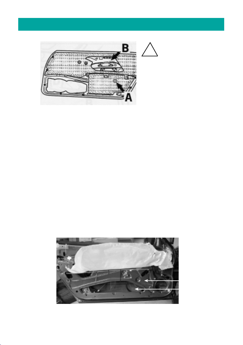
5 . Crossover circuit / Loudspeaker cables
5.1. installation of crossover
5.1.1 precable crossovers –see fig. on page 11
5.2.1 remove housing and install it on the backside of the door lining above
the rear speaker cut-out.
tighten the blank with the original screw and additional washer (see fig.).
Additionally affix the edge of the blank with hot melt adhesive or silicone.
use original fastening
screw under the arm
rest and secure with
20mm washer
affix blank on the plastic clips
fig.: installation of crossover. Backside of door-lining
under the arm rest
75153 - Audi A 4 models from 2001 - 7 - © JEHNERT SOUND DESIGN 75153 - Audi A 4 models from 2001 - 8 - © JEHNERT SOUND DESIGN
6. insulation of the door lining
Important tip:
the use of 2x16mm mid-woofer /side may cause vibrations which lead to
annoying rattle noises in the car door
some helpful tips:
•use our self-adhesive insulation fleece (art.no.: 27000) or a foam material for
the backside of the door lining (see fig. above) or
•stabilize the backside of the door lining by means of a special material
(Glass Fibre Filler or stiffening material)
important: keep the cut-outs for the door-airbags and speakers open
•affix the *backside of the inner door metal with self-adhesive asphalt mats (see fig. * )
•by knocking on the car door, vibrations caused by mechanic parts (e.g. Bowden pull wire etc. )
and wiring harness may be found out. Cover these parts with foamed material, felt or
something like that
•cut off overlapping cable tie (rattle noise)
•adhere felt or foamed material under the original wiring harness
!
Important:
No insulation material behind
- loudspeaker
- door latch lever
- (fig. A): drill a hole for the
installation clip
fig.: backside of the door lining –insulation with our article no.: 27000
moisture protection foil
front side of
inner door metal
*door metal outside
= back side of the
inner door metal
attention –danger !!
No insulation behind the
side-airbags (fig. B)
�
�
5.2. Installation of loudspeaker cables
5.1. carefully remove the moisture protection foil
5.2. insulation of the door lining - Important tips against vibration-noise (s.page.8)
5.3. install cables:
Lead 1 speaker cable (1,5 - 2,5 m 2) from amplifier into the door.
5.4. reinstall the moisture protection foil

7. Montage der Türverkleidung
7.1. Türverkleidung oben in die Türschachtleiste einhängen
7.2. In umgekehrter Reihenfolge wie auf Seite 3 beschrieben wieder befestigen.
7.3. Regenschutzfolie für die Tieftöner u-förmig einschneiden und seitliche
Schnittkanten zur Vermeidung von Vibrationsgeräuschen der Folie
stabilisieren (z.B. mit Packband)
1. Zur Positionierung der Befestigungspunkte 1-11 das passgenau ausgerichtete
Paneel als Schablone verwenden:
•Markierung Befestigungspunkt 1-6_ bereits im Paneel montiert:
durch Aufdrücken des Paneels auf der Türververkleidung - Abdruck sichtbar
•Markierung der Befestigungspunkte 7-11:
mit einem dünnen Vorstecher auf der Türverkleidung markieren.
2. Die Lautsprecheröffnungen auf der Türverkleidung anzeichnen.
3. Paneel wieder abnehmen. Die angezeichneten Lautsprecheröffnungen
auf der Türverkleidung mit einer Stichsäge ausschneiden.
4. Für die einzusetzenden Schrauben die Bohrungen gemäß Markierungen
mit einem 6mm-Bohrer vornehmen.
5. Mitgelieferte M4-Schrauben eindrehen. Türpaneel mit der Türver-
kleidung durch leichtes Festschrauben aller 11x M4-Schrauben fixieren.
Alle Schrauben mit den Unterlagscheiben und Muttern sichern.
6. Nochmals Passgenauigkeit überprüfen und Schrauben festziehen:
Alle Schnittkanten des Paneels müssen umlaufend ohne Spalt
auf der Türverkleidung anliegen.
4. Bearbeitung der Türverkleidung / Montage der Türpaneele
75151 - Audi A 4 Cabrio - 9 - © JEHNERT SOUND DESIGN 75151 - Audi A 4 Cabrio - 6 - © JEHNERT SOUND DESIGN
�
M4 x30
montiert M4 x50
montiert M4 x50
montiert
M4 x50
montiert
M4 x40
montiert
M4 x20
montiert
✍
✍
1
2345
7
9
10 8
M 4 x 20 M 4 x 20 M 4 x 30 M 4 x 30
6
M 4 x 30
11
7. Installation of the door lining onto car door
7.1. Put in the door lining in the sealing above.
7.2. Fit the door lining in contrary order (described on page 3).
7.3. Cut (like a U) the moisture protection foil and stabilize
the edges of the foil against vibrations.
(for example with packing tape)
1. use the precisely aligned panel as template in order to mark fastening points 1- 9:
marking of fixing points 1-9:
use a thin awl to set the marks on the door-lining
2. draw the speakers’cut-outs onto the door-lining.
3. remove the panel again.
cut out holes for loudspeakers along the marking with a compass saw (see fig.)
4. use a 6mm drill for the screws according to the marks set before
5. Screw in the M4-screws supplied with. Affix the door build to the door-lining.
Screw all 9 x M4-screws only hand-tight .
Secure all screws with the washers and nuts.
6. check again for precise fitting and tighten screws.
All cutting edges of the panel must fit to the door lining snugly
all around without gap
cutout for subwoofer
and midrange
4. Handling of door lining / Panel installation - Fastening
75153 - Audi A 4 models from 2001 - 9 - © JEHNERT SOUND DESIGN 75153 - models from 2001 - 6 - © JEHNERT SOUND DESIGN
�
✍
✍
✍
1
M 4 x 30
2345
6
8
9
7
M 4 x 30 M 4 x 40 M 4 x 50 M 4 x 30
M 4 x 30 M 4 x 30 M 4 x 30
M 4 x 30
door lining:
original cutout
evtl. enlarged
zusätzlicher
Ausschnitt für
Tieftöner

8. Frequenzweichenmontage und Lautsprecheranschluss
5.1.1 Frequenzweichen vorverkabeln - vgl. Abb. Seite 11.
5.2.1 Gehäuse entfernen und hinter dem Steg des Türpaneels zwischen
Türverkleidung und Türpaneel einschieben und sicheren Sitz
befestigen.
Tief- und Mitteltöner einsetzen und alle Lautsprecher mit der
Frequenzweiche verkabeln (Paralell-Schaltung):
Hinweis: Bevor alle Tieftöner an die Frequenzweiche angeschlossen werden,
sollte die Polarität aller Tieftöner an einer 9 Volt-Batterie
überprüft werden:
Pol des FW-Eingang an von 9 V Batterie
Pol des FW-Eingang an von 9 V Batterie
Alle Tieftöner müssen bei dieser Überprüfung gleichmäßig ausschwingen!
Ein verpolter Tieftöner kann die gesamte Basswiedergabe
aufheben!
3.1. Türverkleidung auf eine ebene Fläche legen.
3.2. Die auf dem Paneel zur Transportsicherung befestigten Lautsprecher
demontieren. (Schrauben zur späteren Montage aufbewahren).
3.3. Das Paneel ohne Lautsprecher auf die Türverkleidung legen und ausrichten:
Fixpunktlinien zur Anpassung:
Nur die exakte Anpassung des Paneeles auf die Türverkleidung
gewährleistet eine optimale Passgenauigkeit
1. Fixpunktlinie 1:
Paneeloberkante direkt unterhalb der Armlehne anpassen.
2. Fixpunktlinie 2:
Die Paneelunterkante und Unterkante der Türverkleidung schließen paralell ab.
75151 - Audi A 4 Cabrio - 10 - © JEHNERT SOUND DESIGN75151 - Audi A 4 Cabrio - 5- © JEHNERT SOUND DESIGN
3 . Paneelanpassung
�
�
✚ ✚
Fixpunktlinie 1:
Paneeloberkante direkt unterhalb
der Armlehne anpassen
Fixpunktlinie 2:
Unterkante Türverkleidung und
Panelunterkante verlaufen paralell
Nachdem alle Tieftöner an die Frequenzweiche angeschlossen
sind, sollte die Polarität aller Tieftöner an einer 9-Volt-Batterie
überprüft werden (an Weicheneingangskabel auf Endstufenseite).
8. Crossover circuit - Speaker connection
8.1. precable crossovers - see fig. page 11.
8.2. install crossover –without housing; covered with foamed material-
in the hollow space between in the door-lining above the two front woofers and
the original tweeter mount –see fig.).
Check precise fit.
8.3. Insert subwoofer and midrange and connect all loudspeakers
with the included standart cables for subwoofer to the crossover circuit:
parallel wiring see diagram on page 11.
Notice:
You should check the polarity of all subwoofers
before connecting them to the crossover circuit
with a 9 volt battery:
pole of the crossover circuit input to of a 9 Volt battery
pole of the crossover circuit input to of a 9 Volt battery
All subwoofers must move uniformly!
Wrong polarity of a subwoofer can totally
equalize the bass sound!
75152 - Audi TT - 10 - © JEHNERT SOUND DESIGN75152 - Audi TT - 5- © JEHNERT SOUND DESIGN
3 . Panel alignment
3.1. Place the door lining on a plane surface.
3.2. Dismount the loudspeakers attached to the panel for transport protection.
Retain the screws for later assembly.
3.3. Place the panel without loudspeakers and grill on the door lining and align it:
Reference points for fitting:
Only precise alignment of the panel with the door
lining warrants optimal fit.
Reference line 1:
align the ”nose”on the back side of the door build directly
to the notch of the original laudspeaker grill (dismounted)
Reference line 2:
the lower edge of the panel is parallel
to the lower edge of the door lining. (see fig.2)
�
�
✚ ✚
reference line 2:
panel ”nose”has to be aligned directly
to the notch of the original grill
disassembled
reference line 1:
lower edge of panel is
parallel to the lower edge
of the door lining
You should check the polarity of all woofers after having
connected them to the crossover circuit with a 9 volt battery
(input cable on the side of the amplier
install crossover – without housing, covered with foamed material –
in the hollow space between doorboard and doorlining (see g.)
and ensure precise t.

Lautsprecheranschluss - Schaltbild
Alle Lautsprecher und Frequenzweichen anschließen:
H
i
g
h
P
e
r
f
o
r
m
a
n
c
e
D E S I G N
JEHNERT
SoundSound
Midrange
Speaker
MADE INGERMANY
2.1. Plastikrahmen des Hochton-Gitters mit einem Keil ausklipsen und
abnehmen.
2.2. Werkseitiger Hochtöner entfernen und Lautsprecher-Anschlußabstecken.
2.3. JEHNERT-Hochtöner mit Lautsprecherkabel (1,5 - 4mm ) verkabeln
Kabellänge: bis zur Frequenzweiche
Montage unterhalb des Armaturenbrettes
2.4. Das Langlochblech am Hochtöner mittels Unterlagscheibe und 6Ktn.
Schraube befestigen.
2.5. Hochtöner mit dem Langlochblech in die werkseitige Einbauöffnung
einsetzen, Lautsprecherkabel zum Frequenzweichen-Montageort führen,
Langlochblech befestigen.
.
Akustische Empfehlung:
Hochtöner angewinkelt zum Innen-Rückspiegel justieren.
(Nicht zur Fahrer - oder Beifahrerseite!)
H
i
g
h
P
e
r
f
o
r
m
a
n
c
e
DE S I G N
JEHNERT
SoundSound
Tweeter
Speaker
MADE INGERMANY
75151 - Audi A 4 Cabrio - 11 - © JEHNERT SOUND DESIGN 75151 - Audi A 4 Cabrio - 4 - © JEHNERT SOUND DESIGN
Schaltbild 3-Wege Frequenzweiche / 4x Tieftöner
H
i
g
h
P
e
r
f
o
r
m
a
n
c
e
D E S I G N
JEHNERT
SoundSound
WOOFER
Speaker
MADE IN GERMANY
H
i
g
h
P
e
r
f
o
r
m
a
n
c
e
D E S I G N
JEHNERT
SoundSound
WOOFER
Speaker
MADE IN GERMANY
H
i
g
h
P
e
r
f
o
r
m
a
n
c
e
D E S I G N
JEHNERT
SoundSound
WOOFER
Speaker
MADE IN GERMANY
H
i
g
h
P
e
r
f
o
r
m
a
n
c
e
D E S I G N
JEHNERT
SoundSound
WOOFER
Speaker
MADE IN GERMANY
2 . Montage des Hochtöners im Armaturenbrett
�
HochtönerTieftöner
SoundSound
D E S I G N
JEHNERT
MitteltönerEingang
3-Wege fahrzeugspezifische Frequenzweiche
Audi A 4 Cabrio - 75151
= mitgelieferter Kabelstrang
Verstärker
ab 200 Watt RMS / 4 Ohm
empf.Leistung
Loudspeaker wiring diagram
Connect all loudspeakers and crossover circuits:
Loudspeaker wiring diagram
Connect all loudspeakers and crossover circuits:
H
i
g
h
P
e
r
f
o
r
m
a
n
c
e
D E S I G N
JEHNERT
SoundSound
Midrange
Speaker
MADE INGERMANY
TIP:
For a wider stage image we recommend tweeter installation next to the release
lever in the car door:
Tweeter installation above the original mount:
1. mark the outlines of the assembly ring supplied with ( approx. 1cm next
to the release lever) and cut them out exactly by means of a compass saw
( see fig. )
2. Insert the assembly ring and affix with hot melt adhesive
3. clip the tweeter in the ring and secure with washer and hexagon head screw
M4x8. Connect tweeter to loudspeaker cable (1,5 - 2,5 m 2).
(length of cable to crossover in the door-lining above the two front woofers and
the original tweeter mount –see page 10).
Original mount of tweeter
will not be used
H
i
g
h
P
e
r
f
o
r
m
a
n
c
e
DE S I G N
JEHNERT
SoundSound
Tweeter
Speaker
MADE INGERMANY
75152 - Audi TT - 11 - © JEHNERT SOUND DESIGN 75152 - Audi TT - 4 - © JEHNERT SOUND DESIGN
2 . Installation tweeter
mount of tweeter
Circuit diagram of 3-way crossover / 4x subwoofer
H
i
g
h
P
e
r
f
o
r
m
a
n
c
e
D E S I G N
JEHNERT
SoundSound
WOOFER
Speaker
MADE IN GERMANY
H
i
g
h
P
e
r
f
o
r
m
a
n
c
e
D E S I G N
JEHNERT
SoundSound
WOOFER
Speaker
MADE IN GERMANY
H
i
g
h
P
e
r
f
o
r
m
a
n
c
e
D E S I G N
JEHNERT
SoundSound
WOOFER
Speaker
MADE IN GERMANY
H
i
g
h
P
e
r
f
o
r
m
a
n
c
e
D E S I G N
JEHNERT
SoundSound
WOOFER
Speaker
MADE IN GERMANY
�
tweetersubwoofer
SoundSound
D E S I G N
JEHNERT
midrange
input
3-way crossover circuit
Aud i TT - 75 152
= set of cables supplied with
amplifier
from 200 Watt RMS / 4 Ohm
recommended power
distance ca.
1cm
Loudspeaker wiring diagram
Connect all loudspeakers and crossover circuits:
Loudspeaker wiring diagram
Connect all loudspeakers and crossover circuits:
H
i
g
h
P
e
r
f
o
r
m
a
n
c
e
D E S I G N
JEHNERT
SoundSound
Midrange
Speaker
MADE INGERMANY
TIP:
For a wider stage image we recommend tweeter installation next to the release
lever in the car door:
Tweeter installation above the original mount:
1. mark the outlines of the assembly ring supplied with ( approx. 1cm next
to the release lever) and cut them out exactly by means of a compass saw
( see fig. )
2. Insert the assembly ring and affix with hot melt adhesive
3. clip the tweeter in the ring and secure with washer and hexagon head screw
M4x8. Connect tweeter to loudspeaker cable (1,5 - 2,5 m 2).
(length of cable to crossover in the door-lining above the two front woofers and
the original tweeter mount –see page 10).
Original mount of tweeter
will not be used
H
i
g
h
P
e
r
f
o
r
m
a
n
c
e
DE S I G N
JEHNERT
SoundSound
Tweeter
Speaker
MADE INGERMANY
75152 - Audi TT - 11 - © JEHNERT SOUND DESIGN 75152 - Audi TT - 4 - © JEHNERT SOUND DESIGN
2 . Installation tweeter
mount of tweeter
Circuit diagram of 3-way crossover / 4x subwoofer
H
i
g
h
P
e
r
f
o
r
m
a
n
c
e
D E S I G N
JEHNERT
SoundSound
WOOFER
Speaker
MADE IN GERMANY
H
i
g
h
P
e
r
f
o
r
m
a
n
c
e
D E S I G N
JEHNERT
SoundSound
WOOFER
Speaker
MADE IN GERMANY
H
i
g
h
P
e
r
f
o
r
m
a
n
c
e
D E S I G N
JEHNERT
SoundSound
WOOFER
Speaker
MADE IN GERMANY
H
i
g
h
P
e
r
f
o
r
m
a
n
c
e
D E S I G N
JEHNERT
SoundSound
WOOFER
Speaker
MADE IN GERMANY
�
tweetersubwoofer
SoundSound
D E S I G N
JEHNERT
midrange
input
3-way crossover circuit
Aud i TT - 75 152
= set of cables supplied with
amplifier
from 200 Watt RMS / 4 Ohm
recommended power
distance ca.
1cm

1.5. Torx-Schraube (D) unter der Abdeckung der Schalterleiste/Fahrerseite
bzw. Fensterheberschalter/Beifahrerseite entfernen.
1.6. Schraube (E) am unteren Türverkleidungsrand entfernen.
1.7. Türverkleidung vorsichtig nach vorne abnehmen und nach oben wegziehen.
1.8. Türentriegelungsbowdenzug aushängen.
1.9. Elektrischen Anschlußfür Schaltleiste abstecken.
1.10. Original-Lautsprecheranschluss abstecken und werkseitiger Tieftöner demontieren.
1.11. Werkseitiges Kartenfach und Original-Lautsprecher entfernen:
Befestigungsnieten gebm. Abb. auf der Türverkleidungs-Rückseite abhebeln und
komplette Einheit abnehmen.
Abnehmen der Abdeckblenden:
Die Abdeckblenden können durch vorsichtiges Lösen der Klettverschlüsse
jederzeit abgenommen werden.
VORSICHT:
Bitte jede Art von »gewaltsamem Reißen «an den Blenden
vermeiden (Bruchgefahr !)
Abb.: Türverkleidungsrückseite- Demontage werkseitiges Kartenfach
1 . Demontage der Türverkleidung
75151 - Audi A 4 Cabrio - 12 - © JEHNERT SOUND DESIGN75151 - Audi A 4 Cabrio - 3 - © JEHNERT SOUND DESIGN
Die Klettverschlüsse sind ab Werk bereits komplett auf den Abdeckblenden
montiert.
WICHTIG :
Die Klettverschlüsse haften sehr stark!
Die Abdeckblenden deshalb erst nach kompletter Montage der Türpaneele
und Soundsystem fest aufdrücken !
Tipp:
... wenn sich die Abdeckblende an manchen Stellen nicht auf dem
Paneel festdrücken läßt ...
Ursache: Die besondere Formgebung der Türpaneele an dieser Stelle
und die daraus resultierende unterschiedliche Materialstärken
der Abdeckblenden.
Lösung: Mit einer M 4-Unterlagscheibe ø20mm (3) unter dem
Klett-Teller wird dieser Abstand einfach und schnell ausgeglichen:
9. Montage der Abdeckblenden :
�
�
�
Abdeckblende
2 selbstklebendes Klettband
1 Klett-Druckverschluss
3 Unterlagscheibe M4 ø20 als Distanzhilfe
Türpaneel
B
A
1.1. Fensterscheibe komplett herunterlassen.
1.3. Darunterliegende 4 Schrauben (B1+2: Torxschr. / B3+4: Kreuzkopfschr.) entfernen.
D
1.2. Demontage der Holzleiste
(am Fixpunkt A beginnend!)
•Seitenkanten (Abb. A+B) mit
einem Keil vorsichtig nach vorne
abdrücken.
•in Richtung Türschloss schieben
und abziehen.
1.4. Die Abdeckung der Schalter-
leiste/Fahrerseite und Fenster-
heberschalter/Beifahrerseite
durch die Öffnung unterhalb
des Türgriffes herausdrücken.
E
D
C1C2
C3C4
Removing the grills:
The Velcro fasteners stick together very strongly!
The grills can be removed anytime by carefully lifting them off.
Please, avoid any way of forceful yanking at the grills.
It could break!
9.3.
9.2. Our Tip:
If the panel cannot be pressed on completely at some points. . .
Cause: the special form at these points and the resulting differences in
material cross section of the grill.
Solution: the distance can be levelled out with spacers 3 under the
Velcro disc.
(Spacers included with the screw kit)
1.1. Roll down window completely.
1.2. Unscrew the head cap screws at the inner door latch lever (A) and pull away
upward. Remove the head cap screws D1 + D2 underneath.
1.3. Remove the head cap srews C1 + C2 from both sides of the door lining.
1.4. Carefully squeeze the door panel out of the sealing above and simultaneously
move it horizontally and forward away from the inner door metal.
1.5. Unlook door lock Bowden pull wire.
1.6. Pull off the switch of the electric window control.
1.7. Unplug the original cables and remove the original subwoofer.
9.1. Precisely align and carefully press grill into the Velcro fasteners.
The Velcro fastener makes a crackling sound
when it is closed correctly.
A
1 . Disassembly of the door lining
75156 - Audi A 4 - 3 - © JEHNERT SOUND DESIGN 75156 - Audi A 4 - 12 - © JEHNERT SOUND DESIGN
C1
D1D2
C2
�
9. Installation of the speaker’s grill:
grill
2 self-adhesive Velcro-strip
1 Velcro fastener
3 Washer M4 ø20 as spacer
doorpanel

Verpackungseinheit Checkliste
Türpaneele, bezogen (rechts / links) 2
Abdeck-Blenden, bezogen (rechts / links) 4
Hochtöner 26 mm 2
Mitteltöner 100 mm Q (jeweils mit 2 Blechschrauben am Paneel montiert) 2
Tieftöner 160 mm (jeweils mit 2 Blechschrauben am Paneel montiert) 8
Frequenzweichen (rechts / links) 2
serieller Kabelsatz für Tieftöner (rechts / links) je 1
Kleinteile-Beutel:
Schrauben-Senkkopf, M 4 x 20 4
Schrauben-Senkkopf, M 4 x 30 6
6-Ktn.Mutter M 4 22
Unterlagscheiben Ø20mm 22
Unterlagscheiben Ø20mm als Distanzhilfe für Klettverschlüsse 4
Blechschrauben, schwarz 3,9x13(f. Tieftöner) 8
Klettband à2,5 cm (Reserve) 4
Kleinteile-bereits montiert:
Klettverschlüsse + Klettband 16
Schrauben-Senkkopf, M 4 x 20 2
Schrauben-Senkkopf, M 4 x 30 2
Schrauben-Senkkopf, M 4 x 40 2
Schrauben-Senkkopf, M 4 x 50 4
Blechschrauben, schwarz 3,9 x 13 (für Tieftöner) 8
Blechschrauben, schwarz 3,5 x 13 (4xMT+16xKlettv.) 20
Die Ware wurde sorgfältig verpackt und auf ihre Vollständigkeit geprüft. Bei Fehlmengen, Schäden oder Mängel
beachten Sie bitte unsere Garantieleistungen auf der Rückseite dieser Montageanleitung.
Kleinteile-Beutel:
Packliste Art. 75151
75151 - Audi A 4 Cabrio - 13 - © JEHNERT SOUND DESIGN 75151 - Audi A 4 Cabrio - 2 - © JEHNERT SOUND DESIGN
Technische Information
Fahrzeugausstattung: elektrische Fensterheber
Modell/ Modelljahr: A4 Cabrio
Dämmung der Türen: empfohlen
Einstell-Hinweis: Um den optimalen Raumklang zu erzielen,
sollten am Radiogerät sämtliche Einstellungen
(Bass, Höhen, Loudness usw.) auf Null bzw.
neutral eingestellt werden
empfohlene
Verstärkerleistung: ab 2x 200 - 360 Watt sinus / 4 Ohm
Blechschneidearbeiten: entfallen
Lautsprecherausschnitte/ 4 x 144mm (max.AußenmaßTieftöner 165 mm)
pro Seite (max.Einbautiefe Tieftöner 65 mm)
Euro-Norm-Korb passend
1 x 92mm (max.AußenmaßMitteltöner 100 mm)
(max.Einbautiefe Mitteltöner 55 mm)
Sound-System: 3-Wege
4 x 160 mm Tieftöner / Seite
1 x 100 mm Mitteltöner / Seite
1 x 26 mm Hochtöner / Seite
fahrzeugspezifische Frequenzweiche
Belastbarkeit Dauer / Musik: 2 x 300/500Watt
Übertragungsbereich: 49-22.000 Hz
Impedanz: 4 Ohm
Einbauzeit: Einbauprofi: 3-4 Stunden
Änderungen, die dem technischen Fortschritt dienen, bleiben vorbehalten.
Packing unit Check list
door panel, covered (right / left) 2
Speaker grill, covered (right / left) 4
Tweeter 26 mm 2
Tweeter mounting bowl (with 6Ktn.Screw M4x8 u. Washer ø12mm) 2
Midrange 100 mm Q (each mounted on the panel with 4 Sheet metal-screws) 2
Subwoofer 160 mm (each mounted on the panel with 2 Sheet metal-screws) 8
Crossover (right / left) 2
standart cables for subwoofer (right / left) 2
Hardware bag:
Flat head screws, M 4 x 30 12
Flat head screws, M 4 x 40 8
Flat head screws, M 4 x 50 2
Hex nut M 4 22
Washer Ø 20mm 22
Washer Ø 20mm as spacer for Velcro fastener 4
Sheet metal screws, black 3,9x13(f. subwoofer) 16
Velcro strip à 2,5 cm (reserve) 4
Preassembled hardware:
Velcro fastener plus strips 14
Sheet metal screws, black 3,9x13(f. subwoofer) 16
Sheet metal screws, black 3,5x13 (8xMR+14xVelcro.) 22
The product was carefully packed and checked for its completeness. If you find anything missing, damaged or
defective, please notice our guarantee services on the back of these assembly instructions.
standart cables for subwoofer (right / left)
Packing list 75152
75152 - Audi TT - 13 - © JEHNERT SOUND DESIGN 75152 - Audi TT - 2 - © JEHNERT SOUND DESIGN
Technical information
Equipment: electric window control
Model/ year : coupé / roadster
Insulation: Insulation not necessary
Note about setting: To obtain optimal stereoscopic sound, all settings
on the radio (bass, treble, loudness etc) should be
set to zero or neutral.
Recommended
amplifier power : from 2x 200 - 360 Watt RMS / 4 Ohm
Metal cutwork : not necessary
Cut-outs for loudspeaker/ 4 x 144mm (max.outer dimensions subwoofer 165 mm)
each side (max.installation depth subwoofer 65 mm)
DIN-Euro-Norm-standard basket ø6“-
panel modification necessary
1 x 92mm (max.outer dimensions midrange 100 mm)
(max.installation depth midrange 60 mm)
Sound-System: 3-ways
4 x 160 mm subwoofer/ side
1 x 100 mm midrange / side
1 x 26 mm tweeter / side
car-customized crossover network
max.continuous Watt/RMS: 2 x 300/500Watt
car specific frequency range: 49-22.000 Hz
Total impedance: 4 Ohm
Time for Installation car hifi-specialist: 3 hours
We reserve the right to make technical changes, as well as development.
55 mm)
is recommended
A4 Convertible

Packliste ..............................................................................
1. Demontage der Türverkleidung...............................................
2. Montage des Hochtöners .......................................................
3. Paneelanpassung ..................................................................
4. Bearbeiten der Türverkleidung / Montage der Türpaneele..........
5. Frequenzweichenmontage + Lautsprecherleitungen .................
6. Dämmung der Türverkleidung / Fahrzeugtüren ........................
7. Montage der Türverkleidung ..................................................
8. Lautsprecheranschluss ..........................................................
Lautsprecheranschluss - Schaltbild ........................................
9. Montage der Lautsprecher-Abdeckblenden .............................
Technische Informationen .....................................................
Service / Fehlersuche............................................................
Garantie .............................................................................
Steffen Kretzschmar
Sattlerei / Produktionsablauf
Durchwahl: - 69
Seite
2
3
4
5
6
7
8
9
10
11
12
13
14
15
75151 - Audi A 4 Cabrio - 14 - © JEHNERT SOUND DESIGN75151 - Audi A 4 Cabrio - 1 - © JEHNERT SOUND DESIGN
Technische Fragen: Info-Hotline: 0711 - 77 97 87 - 87
Wir danken für Ihre Unterstützung !
Mirko Schwarz
Produktentwicklung / Qualität
Durchwahl: - 67
Wir helfen Ihnen gerne weiter!
Sehr geehrter Kunde,
Wir haben uns sehr bemüht unsere neuen Montageanleitungen ausführlicher und
“Schritt für Schritt”zu erklären.
Ihre Tipps und Anregungen helfen uns künftige Unklarheiten oder Fehlinter-
pretationen weiter auszuschließen.
Teilen Sie uns deshalb mit, was Ihnen nicht gefällt oder was wir noch ändern sollten.
Marc Sitter
Versand / Service
Durchwahl: - 68
Marc Sitter
Versand / Service
Durchwahl: - 68
Die folgenden Hinweise sollen Ihnen dabei helfen, Fehler oder Störungen selbst zu
beheben. Wenn folgende Abhilfemaßnahmen nicht greifen, rufen Sie uns bitte an:
Was kann es sein ... mögliche Ursache / Lösung
wenn’s nicht richtig klingt Tieftöner verpolt ( Seite 10)
Frequenzweichen falsch angeschlossen ( Seite 11)
Türverkleidung und Regenschutzfolie
nicht ausgeschnitten ( Seite 7+9)
Verstärker zu wenig Leistung ( Seite 13)
Verstärker-Anschluss
wenn’s nicht richtig passt Fixpunkte Türpaneelanpassung ( Seite 6)
Montage der Paneele auf die TV ( Seite 7)
Abdeckungen nicht haften Hinweise Seite 12 beachten!
Vibrationsgeräusche Dämmung s. Hinweise Seite 8
Selbsthilfe und Fehlersuche
Inhaltsverzeichnis
Besonders wichtige Hinweise enthalten folgende Markierung:
�
Bitte folgen Sie den Anweisungen der Montageanleitung
“Schritt für Schritt”
und prüfen Sie den Packungsinhalt
Packliste ..............................................................................
1. Demontage der Türverkleidung...............................................
2. Montage des Hochtöners .......................................................
3. Paneelanpassung ..................................................................
4. Bearbeiten der Türverkleidung / Montage der Türpaneele..........
5. Frequenzweichenmontage + Lautsprecherleitungen .................
6. Dämmung der Türverkleidung / Fahrzeugtüren ........................
7. Montage der Türverkleidung ..................................................
8. Lautsprecheranschluss ..........................................................
Lautsprecheranschluss - Schaltbild ........................................
9. Montage der Lautsprecher-Abdeckblenden .............................
Technische Informationen .....................................................
Service / Fehlersuche............................................................
Garantie .............................................................................
Steffen Kretzschmar
Sattlerei / Produktionsablauf
Durchwahl: - 69
Seite
2
3
4
5
6
7
8
9
10
11
12
13
14
15
75151 - Audi A 4 Cabrio - 14 - © JEHNERT SOUND DESIGN75151 - Audi A 4 Cabrio - 1 - © JEHNERT SOUND DESIGN
Technische Fragen: Info-Hotline: 0711 - 77 97 87 - 87
Wir danken für Ihre Unterstützung !
Mirko Schwarz
Produktentwicklung / Qualität
Durchwahl: - 67
Wir helfen Ihnen gerne weiter!
Sehr geehrter Kunde,
Wir haben uns sehr bemüht unsere neuen Montageanleitungen ausführlicher und
“Schritt für Schritt”zu erklären.
Ihre Tipps und Anregungen helfen uns künftige Unklarheiten oder Fehlinter-
pretationen weiter auszuschließen.
Teilen Sie uns deshalb mit, was Ihnen nicht gefällt oder was wir noch ändern sollten.
Marc Sitter
Versand / Service
Durchwahl: - 68
Marc Sitter
Versand / Service
Durchwahl: - 68
Die folgenden Hinweise sollen Ihnen dabei helfen, Fehler oder Störungen selbst zu
beheben. Wenn folgende Abhilfemaßnahmen nicht greifen, rufen Sie uns bitte an:
Was kann es sein ... mögliche Ursache / Lösung
wenn’s nicht richtig klingt Tieftöner verpolt ( Seite 10)
Frequenzweichen falsch angeschlossen ( Seite 11)
Türverkleidung und Regenschutzfolie
nicht ausgeschnitten ( Seite 7+9)
Verstärker zu wenig Leistung ( Seite 13)
Verstärker-Anschluss
wenn’s nicht richtig passt Fixpunkte Türpaneelanpassung ( Seite 6)
Montage der Paneele auf die TV ( Seite 7)
Abdeckungen nicht haften Hinweise Seite 12 beachten!
Vibrationsgeräusche Dämmung s. Hinweise Seite 8
Selbsthilfe und Fehlersuche
Inhaltsverzeichnis
Besonders wichtige Hinweise enthalten folgende Markierung:
�
Bitte folgen Sie den Anweisungen der Montageanleitung
“Schritt für Schritt”
und prüfen Sie den Packungsinhalt
Technische Fragen: Info-Hotline 0 71 58 / 9 56 99-0
Technical questions: Hotline 00 49 71 58 / 9 56 99-0
Packing list ..........................................................................
1. Disassembly of the door lining ..............................................
2. Installation tweeter ..............................................................
3. Panel alignment / reference points ........................................
4. Handling of door lining / Panel installation - Fastening ...........
5. Loudspeaker cables .............................................................
6. Insulation of the door lining / car doors .................................
7. Installation of the door lining ................................................
8. Crossover circuit - Speaker connection ..................................
Loudspeaker wiring diagram .................................................
9. Installation of the speaker-grills .............................................
Technical information ...........................................................
Service / fault diagnoses .......................................................
Guarantee ...........................................................................
Steffen Kretzschmar
Saddlery / Completion
page
2
3
4
5
6
7
8
9
10
11
12
13
14
15
75153 - Audi A 4 models from 2001 - 14 - © JEHNERT SOUND DESIGN75153 - Audi A 4 models from 2001 - 1 - © JEHNERT SOUND DESIGN
Technical questions Hotline: 0049-711-77 97 87-87
We thank you for your support!
Mirko Schwarz
Development
It is our pleasure to help you!
Dear customer,
We have taken great care to explain the procedures in our installation instructions
more detailed and “step by step”.
Your tips and suggestions help us for the future to eliminate uncertainties and
misinterpretation. Therefore, please inform us. what you would like to be improved
or what we should still change.
Marc Sitter
Export / Service
Marc Sitter
Export / Service
The following notes serve to help troubleshoot and eliminate faults or malfunctions
on your own. If the following measures are not effective, please call us.
What can it be if ... possible cause/ solution
..it doesn’t sound right. wrong polarity on the subwoofers ( page 10)
crosover circuit attached wrong ( page 11)
Doorlining and moisture protection foil
not cut out ( page 5+10)
amplifier doesn’t have enough power( page 13)
amplifier connection
...it doesn’t fit correctly. door panel customization ( page 8)
installation of the panels on the door lining (page 9)
.....grills do not hold. observe notes on page 12!
vibrations insulation, see notes on page 7
Self-help and fault diagnosis
Contents
Particularly important notes contain the following remarks:
�
Please follow the installation instructions
“step by step”
and check the package contents
6)
7)
8
7 + 9)
Packing list ..........................................................................
1. Disassembly of the door lining ..............................................
2. Installation tweeter ..............................................................
3. Panel alignment / reference points ........................................
4. Handling of door lining / Panel installation - Fastening ...........
5. Loudspeaker cables .............................................................
6. Insulation of the door lining / car doors .................................
7. Installation of the door lining ................................................
8. Crossover circuit - Speaker connection ..................................
Loudspeaker wiring diagram .................................................
9. Installation of the speaker-grills .............................................
Technical information ...........................................................
Service / fault diagnoses .......................................................
Guarantee ...........................................................................
Steffen Kretzschmar
Saddlery / Completion
page
2
3
4
5
6
7
8
9
10
11
12
13
14
15
75153 - Audi A 4 models from 2001 - 14 - © JEHNERT SOUND DESIGN75153 - Audi A 4 models from 2001 - 1 - © JEHNERT SOUND DESIGN
Technical questions Hotline: 0049-711-77 97 87-87
We thank you for your support!
Mirko Schwarz
Development
It is our pleasure to help you!
Dear customer,
We have taken great care to explain the procedures in our installation instructions
more detailed and “step by step”.
Your tips and suggestions help us for the future to eliminate uncertainties and
misinterpretation. Therefore, please inform us. what you would like to be improved
or what we should still change.
Marc Sitter
Export / Service
Marc Sitter
Export / Service
The following notes serve to help troubleshoot and eliminate faults or malfunctions
on your own. If the following measures are not effective, please call us.
What can it be if ... possible cause/ solution
..it doesn’t sound right. wrong polarity on the subwoofers ( page 10)
crosover circuit attached wrong ( page 11)
Doorlining and moisture protection foil
not cut out ( page 5+10)
amplifier doesn’t have enough power( page 13)
amplifier connection
...it doesn’t fit correctly. door panel customization ( page 8)
installation of the panels on the door lining (page 9)
.....grills do not hold. observe notes on page 12!
vibrations insulation, see notes on page 7
Self-help and fault diagnosis
Contents
Particularly important notes contain the following remarks:
�
Please follow the installation instructions
“step by step”
and check the package contents

SoundSound
D E S I G N
JEHNERT
AUDI A 4 mod.from 2001
Guarantee
�
2001/by.AJ/FH - 15 -
Installation instructions
Montageanl.Art. 75153/FH07.01
item-no. 75153
Jehnert Sound Design
development and
production of
Car-Audio-Systems
Heinrich-Hertz-Str. 11
70794 Filderstadt
Tel.: 0711-77 97 87- 87
Fax: 0711-77 78 921
www.jehnert.com
We grant a manufacturers guarantee of 2 years starting from the date of purchase
of the door panels or sound system from the dealer.
Within this guarantee period to our choice we either repair or replace free of
charge all defects due to material or workmanship.
Exempt from this guarantee are damages due to improper use, wear and tear or
damages which have to be led back on wear or interventions by third parties.
The guarantee does not cover subsequent damages or such defects that only
insignificantly impair the value or the usability of the panels/sound system.
The guarantee does not cover damages due to external influences.
Panels with additional or wrong assembly drill holes cannot be returned.
These are damages to the panel which cannot be repaired again.
Table of contents
Other JEHNERT SOUND DESIGN Car Speakers manuals

JEHNERT SOUND DESIGN
JEHNERT SOUND DESIGN AUDI 80 convertible User manual

JEHNERT SOUND DESIGN
JEHNERT SOUND DESIGN 75170 User manual

JEHNERT SOUND DESIGN
JEHNERT SOUND DESIGN 68501 User manual

JEHNERT SOUND DESIGN
JEHNERT SOUND DESIGN VW T5 User manual

JEHNERT SOUND DESIGN
JEHNERT SOUND DESIGN 65740 User manual


