JEKKO SPX532 User manual
1
SPX532 – QUICKSTART GUIDE
REVISION
1
ISSUED BY
ENRICO P.
DATE OF RELEASE
13/03/2020
REVISIONED BY
IGOR P.
DATE OF REVISION
13/03/2020
APPLIED TO
MODELS
SPD-SERIES
SPD265
SPD360
SPD500
JF-SERIES
JF30 JF40 JF365 JF545 JF990
SPX-JUNIOR
SPB209 SPX312 SPX424 SPX429
SPX-SENIOR
SPX527 SPX536 SPX1040 SPX1275
MPK-SERIES
MPK20 MPK50
NEW SERIE
SPX532 SPX1280
OTHERS
SPK 60 OTHER TOOLS INSTRUMENT
SPX532
Quickstart Guide

2
SPX532 – QUICKSTART GUIDE
INDEX
1. TURN ON THE POWER ....................................................................................................................................................................................... 3
2. RELEASE THE EMERGENCY BUTTON ................................................................................................................................................................... 4
3. POWER UNIT SELECTION.................................................................................................................................................................................... 5
4. TURN ON THE REMOTE CONTROL ...................................................................................................................................................................... 6
5. START/STOP DIESEL ENGINE (OR POWER PACK)................................................................................................................................................. 7
6. CONFIRM LMI CONFIGURATION ........................................................................................................................................................................ 8
7. MODIFY LMI CONFIGURATION........................................................................................................................................................................... 9
8. WORKING MODE SELECTION ............................................................................................................................................................................11
9. TRACKS ............................................................................................................................................................................................................13
10. OUTRIGGERS UP & DOWN ................................................................................................................................................................................16
11. CRANE..............................................................................................................................................................................................................23
12. PICK & CARRY...................................................................................................................................................................................................26
13. MACHINE STABILITY (NO FUNCTIONS AVAILABLE) ............................................................................................................................................30
14. ENGINE POWER MODE SELECTOR .....................................................................................................................................................................32
15. WINCH SPEED REDUCTION SELECTOR ...............................................................................................................................................................33
16. CRANE SPEED REDUCTION SELECTOR................................................................................................................................................................34
17. ALARMS & WARNINGS .....................................................................................................................................................................................35

3
SPX532 – QUICKSTART GUIDE
1. TURN ON THE POWER
Go to the right side of the machine’s central frame, where the
main switch is placed.
On the right side panel there are the following devices:
•main power switch (1);
•main power led indicator (2);
•emergency button (3);
•power unit switch selector (4);
•hour counter (5).
Turn on the Main power switch to energize the machine (the Main
power led indicator will turn on).
RIGHT SIDE PANEL
4
SPX532 – QUICKSTART GUIDE
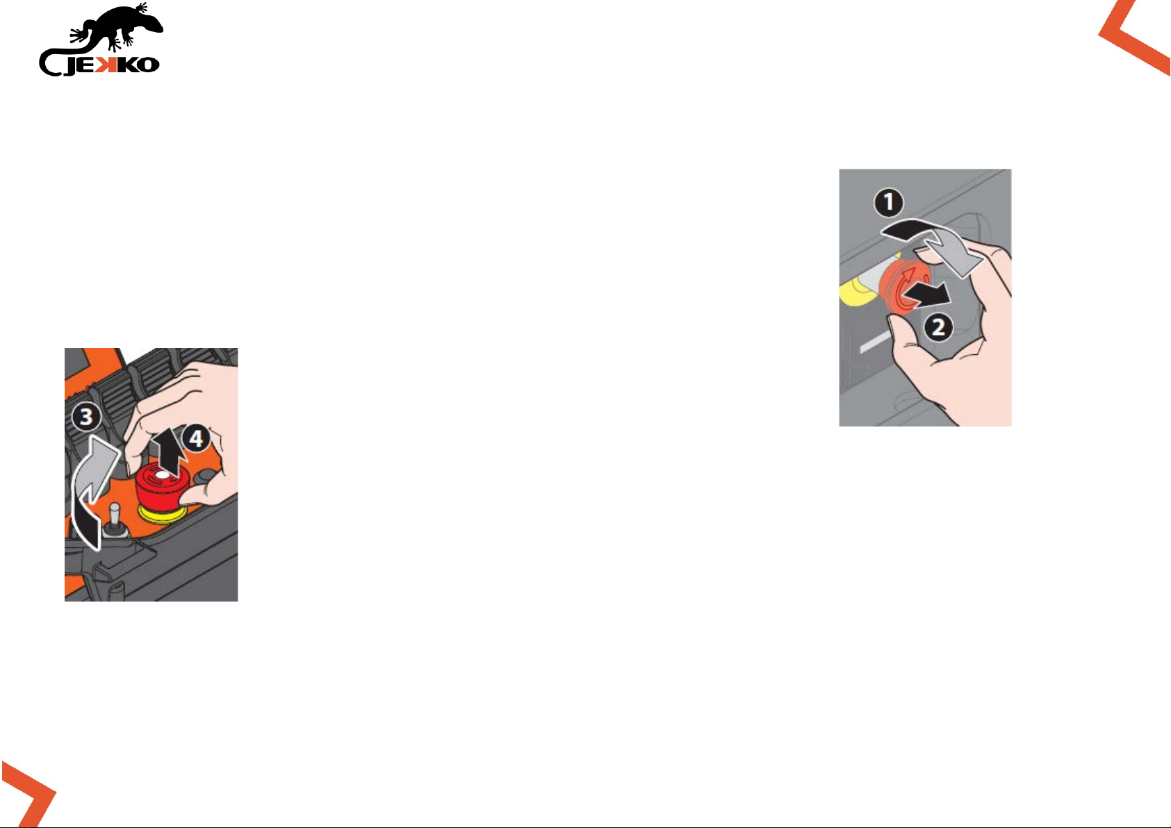
2. RELEASE THE EMERGENCY BUTTON
Check and release the emergency button on the right side panel of the
machine.
Check and release the emergency button on the remote control.
5
SPX532 – QUICKSTART GUIDE
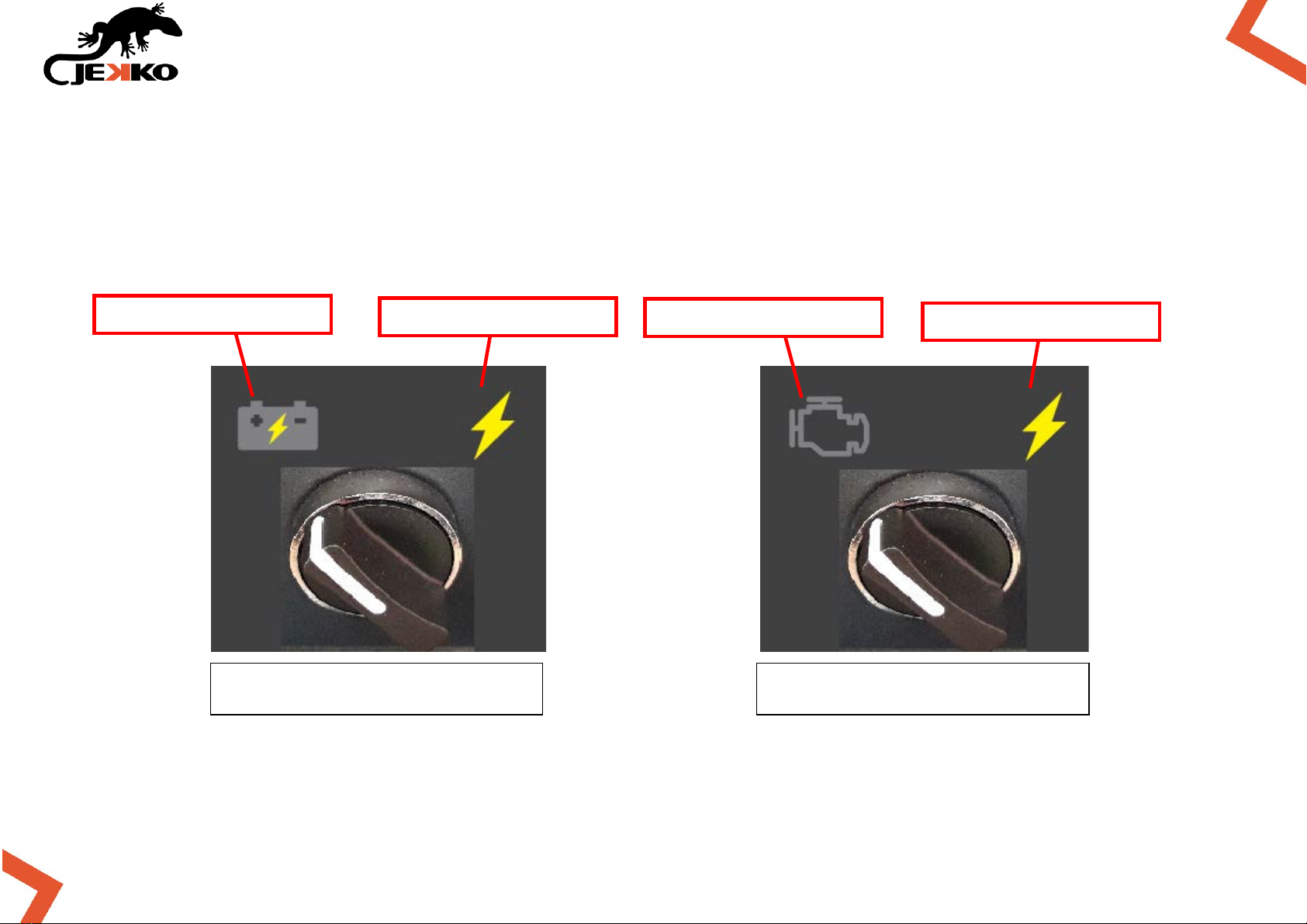
3. POWER UNIT SELECTION
By rotating the Power unit switch selector (located on right side panel) it will be possible to engage
the desired power unit:
*if power pack is present.
SPX532CL version
SPX532CDH version
LITHIUM BATTERY PACK
POWER PACK *
DIESEL ENGINE
POWER PACK *
6
SPX532 – QUICKSTART GUIDE
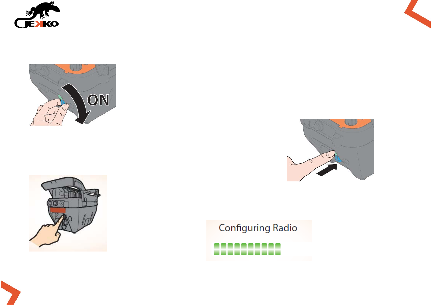
4. TURN ON THE REMOTE CONTROL
Turn on the remote control key.
Press once the Start button on the left side of the remote control
and wait for “Loading HMI …” (about 5 sec.)
When requested on the screen, press again the Start button and wait for
“Configuring Radio”.

7
SPX532 – QUICKSTART GUIDE
5. START/STOP DIESEL ENGINE (OR POWER PACK)
To start the diesel engine on SPX532CDH version (or the power pack electric motor), use the Engine
start/stop selector on the remote control:
START DIESEL ENGINE / POWER PACK
TURN OFF DIESEL ENGINE / POWER PACK
OR PRE-HEAT THE PLUGS (IF DIESEL ENGINE IS SELECTED AND IS OFF)
NOTE FOR SPX532CL MODEL ONLY:
The lithium battery pack power unit doesn’t need to be started/stopped using the Engine selector:
as soon as one or more functions are operated from the remote control, the electric motor is
activated and the pump starts/stops running automatically.
8
SPX532 – QUICKSTART GUIDE
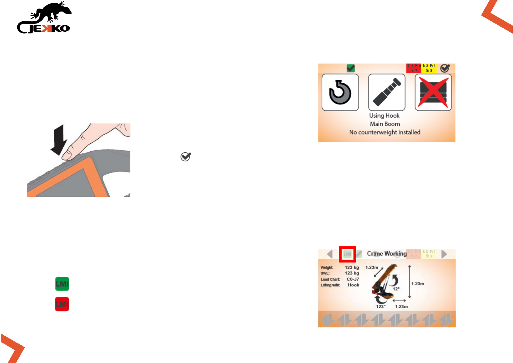
6. CONFIRM LMI CONFIGURATION
The LMI configuration page will be displayed automatically (see
the picture beside).
Press the button (on top of the screen to the right) to confirm the LMI
configuration.
IMPORTANT:
Always check the congruity between the LMI configuration on the display and the real
configuration of the machine!
Once the LMI settings are confirmed, the LMI icon on top of the
screen will become green:
LMI CONFIGURATION CONFIRMED
LMI CONFIGURATION NOT CONFIRMED

9
SPX532 – QUICKSTART GUIDE
7. MODIFY LMI CONFIGURATION
Only if needed, use the Line falls selector to modify the LMI configuration and set the correct
number of rope lines/falls or the hook mode:
INCREASE THE ROPE LINE FALLS NUMBER
PRESS ONCE TO GO BACK TO HOOK MODE IMMEDIATELY
7.1. LMI possible configurations
NOTE:
The machine recognizes automatically the tool installed, thanks to the Plug&Play feature.
The operator is responsible to properly set the rope line falls or hook mode.
MAIN BOOM:
Hook mode
1 line
2lines
3 lines
4 lines
JIB1000.2HL1MX:
Hook mode
1 line

10
SPX532 – QUICKSTART GUIDE
7.2. SELECTION JIB ON BOARD
From LMI configuration page it is possible to select jib
on board by pressing Button 3.
Jib on board icon legend
JIB PARKED ON BOARD: the LMI takes in count
the weight of the jib parked on the boom
JIB NOT ON BOARD: the LMI doesn’t take in
count the weight of the jib
NOTE:
On SPX532 the counterweight is not removable!

11
SPX532 – QUICKSTART GUIDE
8. WORKING MODE SELECTION
Turn the Working mode selector to select the desired working mode:
Pick & Carry
Tracks
Crane
Outriggers Up & Down
Machine stability (no functions available)
IMPORTANT:
BY ROTATING THE WORKING MODE SELECTOR THE MACHINE’S FUNCTIONS WILL BE DISABLED!
Each time that the working mode changes by rotating the selector, the functions must be enabled
again BY PRESSING THE START BUTTON ON THE REMOTE CONTROL!
PAY ATTENTION! TURRET ROTATION ENABLED!
12
SPX532 – QUICKSTART GUIDE
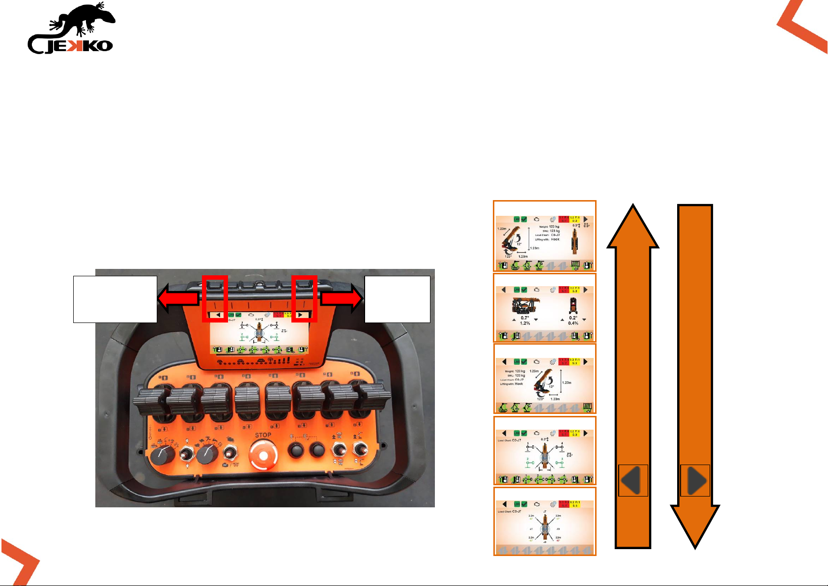
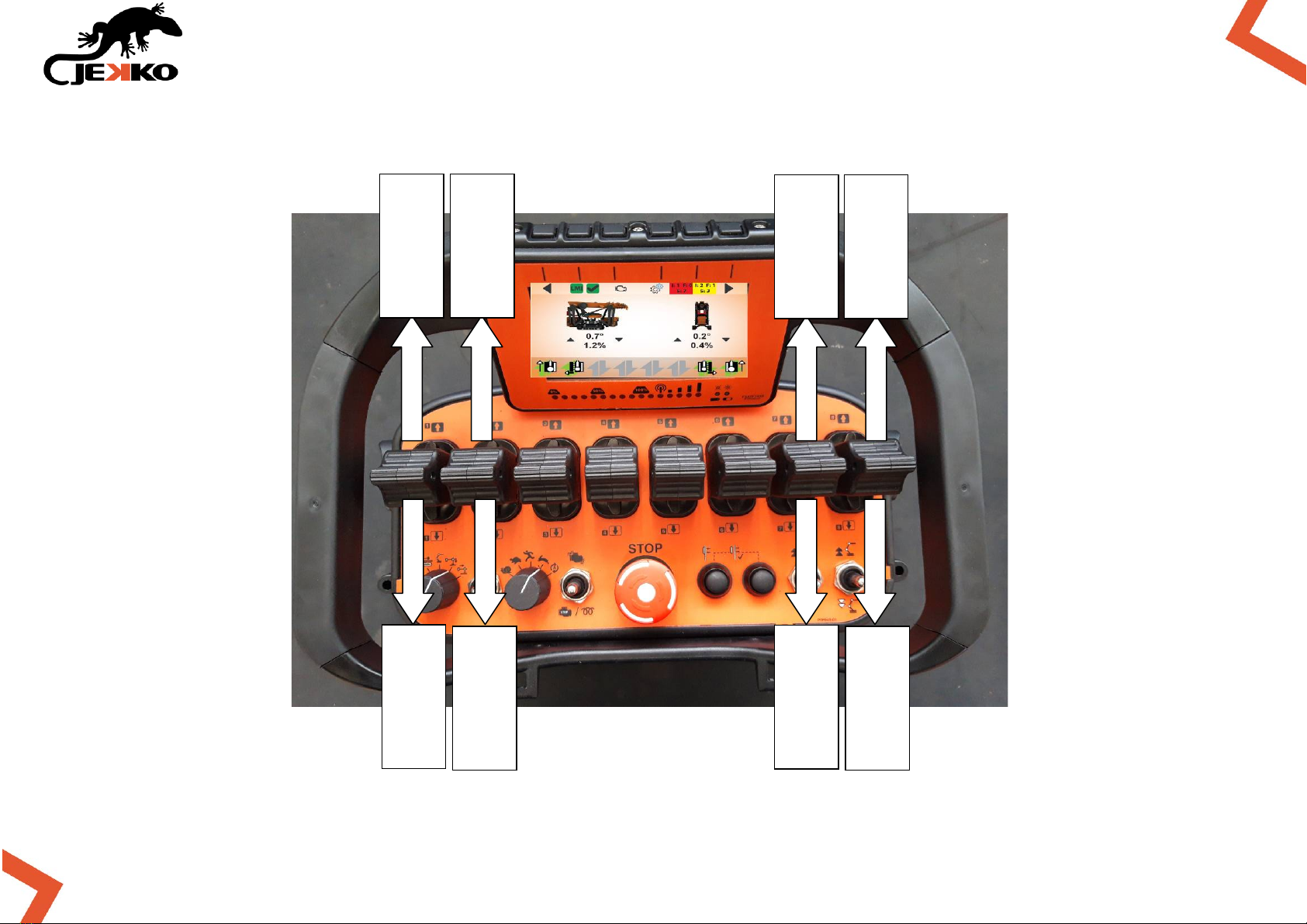
8.1.HOW TO SCROLL WORKING MODE’S PAGES
IMPORTANT:
AVOID TO ROTATE THE WORKING MODE ROTARY SWITCH TO VISUALIZE THE WORKING PAGES!
YOU WILL DISABLE THE MACHINE FUNCTIONS AND IF THE CONDITIONS TO ENABLE THE WORKING
MODE AGAIN ARE NOT SATISFIED, THIS CAN LEAD TO A LOCKED SITUATION!
It’s warmly suggested to scroll the working pages by pressing
the Arrows buttons on top of the screen, so the machine
remains enabled and the working mode doesn’t change.
Previous
page
Next
page
Pick&Carry page
Tracks page
Crane page
Outriggers page
Stability page
P
R
E
S
S
B
U
T
T
O
N
P
R
E
S
S
B
U
T
T
O
N
13
SPX532 – QUICKSTART GUIDE
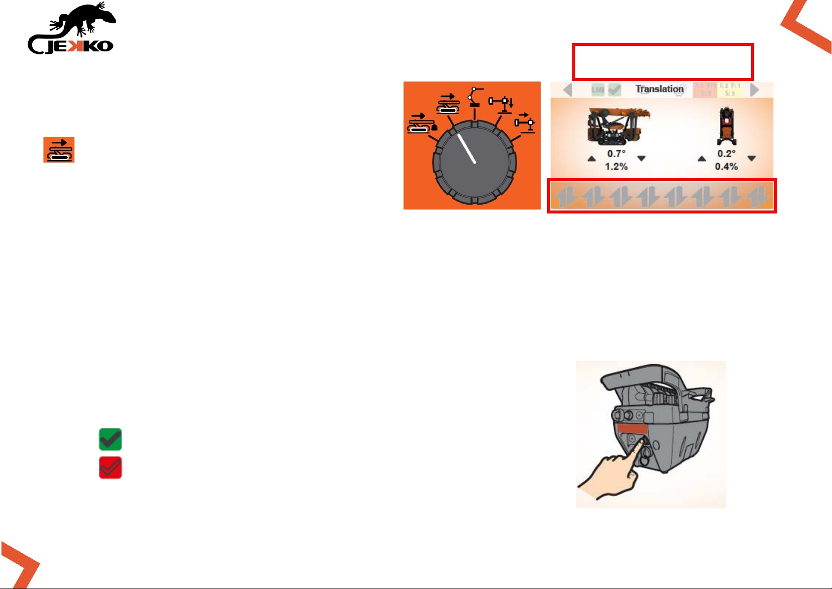
9. TRACKS
Rotate the Working mode selector in position
and the Tracks page will be displayed on
the screen (see the picture beside).
IMPORTANT:
If the icons of the levers are not displayed on bottom of the screen, the working mode needs to be
enabled!
9.1.ENABLE TRACKS FUNCTIONS
To enable the translation functions press once the Start button on the remote control.
The conditions to enable tracks functions are in the next page.
Once the functions are enabled, the Machine enabled icon (on top of
the screen) will become green and the icons of the levers will appear
(on the bottom of the screen).
MACHINE WORKING MODE ENABLED
MACHINE WORKING MODE NOT ENABLED
NO ICONS = WORKING MODE
NOT ENABLED
14
SPX532 – QUICKSTART GUIDE
9.2.CONDITIONS TO ENABLE TRACKS
The following conditions must be respected to enable the tracks functions:
•All 4 outriggers lifted from the ground;
•Crane must be in parking position (0° or 180° ±3°);
•Main boom telescopic FULLY RETRACTED;
•Main boom angle ≤ 45°;
•NO LOAD on tip of the boom;
•If hydraulic jib is installed, it must be fully retracted.
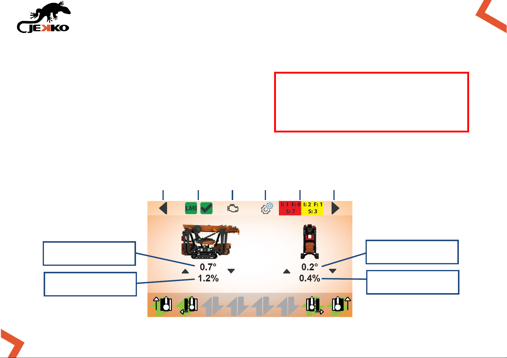
9.3.TRACKS SCREEN APPEREANCE
If these conditions are not respected,
the icons of the levers won’t appear on
bottom of the screen and it won’t be
possible to operate the functions.
Previous
page
LMI config
page
Engine
page
Settings
page
Warning &
alarms page
Next
page
FRONT/BACK INCLINATION
[ ° ]
FRONT/BACK INCLINATION
[ % ]
LEFT/RIGHT INCLINATION
[ ° ]
LEFT/RIGHT INCLINATION
[ % ]
15
SPX532 – QUICKSTART GUIDE
9.4.TRACKS FUNCTIONS
LEFT TRACK
FORWARD
EXTEND LEFT
TRACK
EXTEND RIGHT
TRACK
RIGHT TRACK
FORWARD
RETRACT RIGHT
TRACK
RIGHT TRACK
BACKWARD
LEFT TRACK
BACKWARD
RETRACT LEFT
TRACK
16
SPX532 – QUICKSTART GUIDE
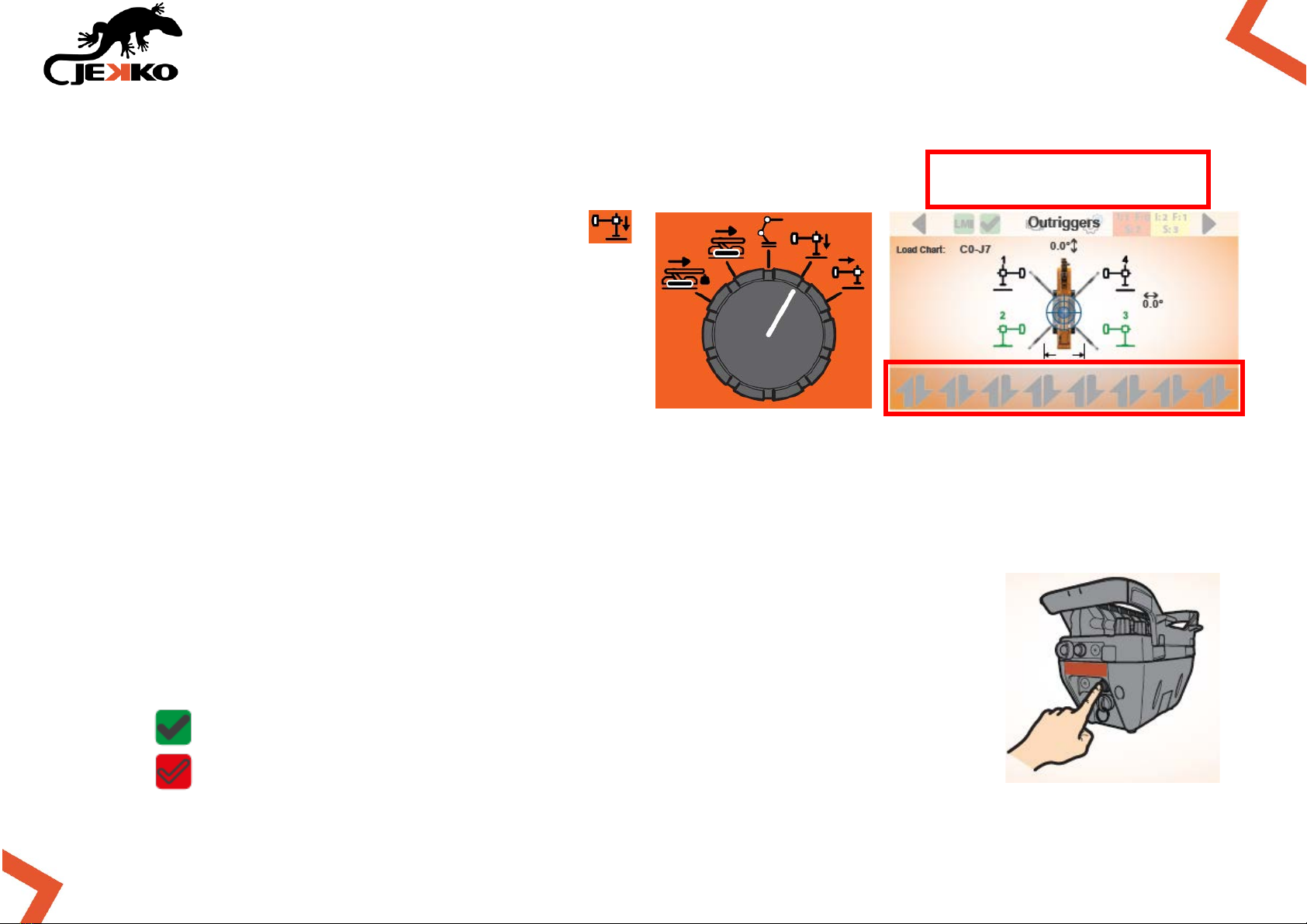
10. OUTRIGGERS UP & DOWN
Rotate the Working mode selector in position
and the Outriggers page will be displayed (see
picture beside).
IMPORTANT:
If the icons of the levers are not displayed on
bottom of the screen, the working mode needs to
be enabled!
10.1. ENABLE OUTRIGGERS FUNCTIONS
To enable the outriggers functions press once the Start button on the remote control.
The conditions to enable outriggers up & down functions are in the next page.
Once the functions are enabled, the Machine enabled icon (on top of the screen)
will become green and the icons of the levers will appear (on the bottom of the
screen).
MACHINE WORKING MODE ENABLED
MACHINE WORKING MODE NOT ENABLED
NO ICONS = WORKING MODE
NOT ENABLED

17
SPX532 – QUICKSTART GUIDE
10.2. CONDITIONS TO ENABLE OUTRIGGERS UP & DOWN
The following conditions must be respected to enable the outriggers up & down functions:
•Crane must be in parking position (0° or 180° ±3°);
•Main boom telescopic FULLY RETRACTED;
•Main boom angle ≤ 45°;
•NO LOAD on tip of the boom;
•If hydraulic jib is installed, it must be fully retracted.
10.3. OUTRIGGERS UP & DOWN SCREEN APPEREANCE
If these conditions are not respected, the
icons of the levers won’t appear on bottom
of the screen and it won’t be possible to
operate the functions.
LMI config
page
Engine
page
Settings
page
Warning &
alarms page
Next
page
ACTUAL CONFIG. AND
LOAD CHART
C = CONFIGURATION
J = LOAD CHART
FRONT/BACK INCLINATION
ON THE GROUND
CLEAR FROM GROUND
LEFT/RIGHT INCLINATION
TRACKS EXTENDED
TRACKS RETRACTED
Previous
page
ON THE GROUND
CLEAR FROM GROUND
ON THE GROUND
CLEAR FROM GROUND
ON THE GROUND
CLEAR FROM GROUND

18
SPX532 – QUICKSTART GUIDE
10.4. OUTRIGGERS UP & DOWN FUNCTIONS
LEFT TRACK
FORWARD
EXTEND LEFT
TRACK
EXTEND RIGHT
TRACK
RIGHT TRACK
FORWARD
RETRACT RIGHT
TRACK
RIGHT TRACK
BACKWARD
LEFT TRACK
BACKWARD
RETRACT LEFT
TRACK
OUTRIGGER 1
DOWN
OUTRIGGER 1 UP
OUTRIGGER 2
DOWN
OUTROIGGER 2 UP
OUTRIGGER 3
DOWN
OUTRIGGER 3 UP
OUTRIGGER 4
DOWN
OUTRIGGER 4 UP
WARNING!
The tracks drive and tracks
extension are always enabled
when the outriggers mode is
enabled!

19
SPX532 – QUICKSTART GUIDE
10.5. OUTRIGGERS OPENING ANGLES (SWING FUNCTION)
Possible outriggers opening angles: 0° - 20° - 47° - 68° - 90°.
All outriggers at 0°
All outriggers at 20°
All outriggers at 47°
The machine can work with
differentiated areas and in
many different outriggers
configurations.
NOTE:
For further details about the
overall dimensions check the
Technical data.
All outriggers at 68°
All outriggers at 90°
20
SPX532 – QUICKSTART GUIDE
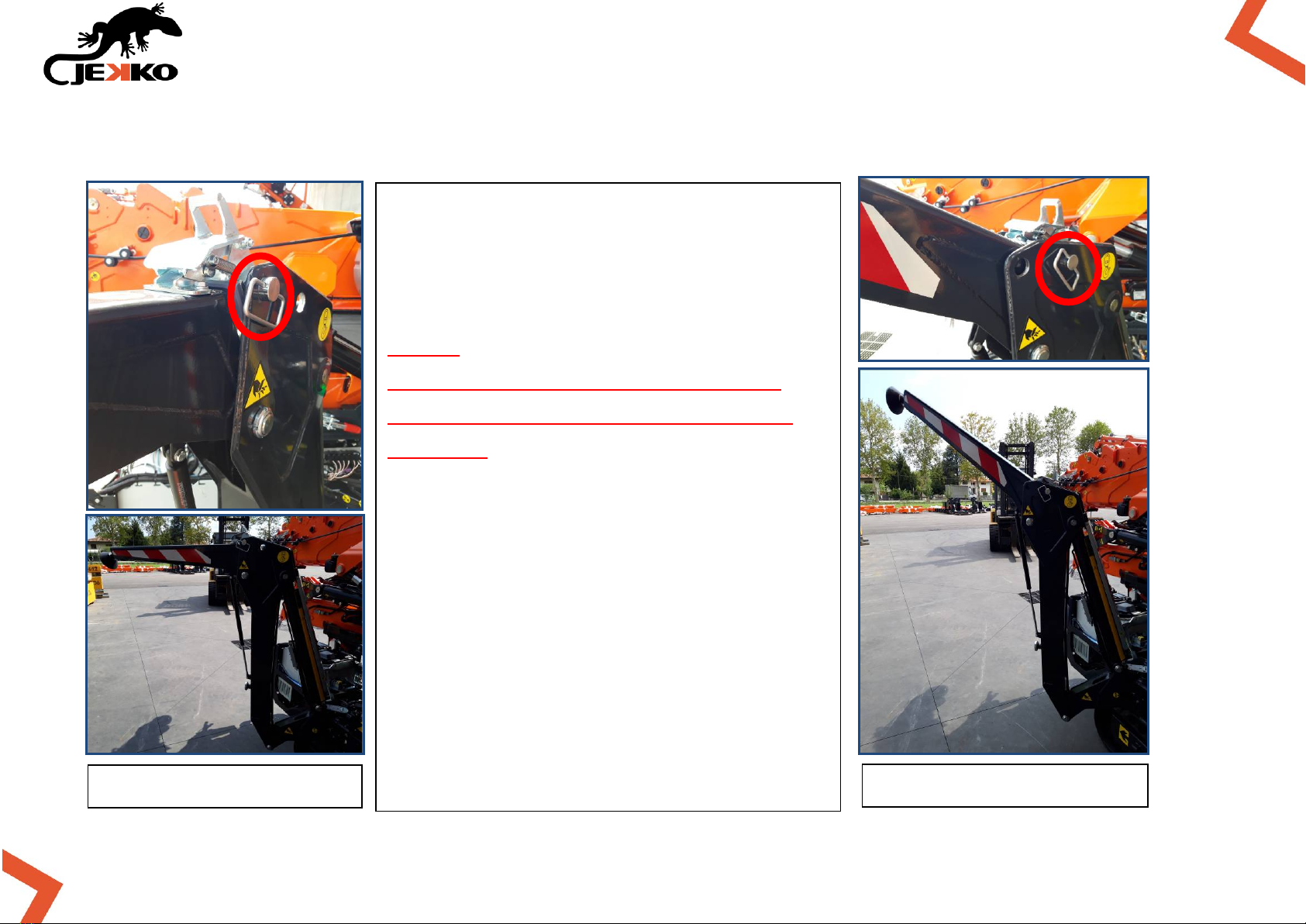
10.6. OUTRIGGERS EXTENSION
Possible outriggers extension positions: 2.15m or 2.62m.
Outrigger retracted
Outrigger extended
The load charts are calculated
according to the outriggers opening
angles (swing) and extension.
NOTE:
When the outrigger is in retracted
position, the lifting capacity will be
de-rated
(less stability = less capacity)
Each outrigger has got two sensors:
•on ground position sensor;
•outrigger extension sensor.
The machine can be operated in
differentiated lifting capacity areas
applying different load charts
according to the stability conditions.
Table of contents
Other JEKKO Construction Equipment manuals


Popular Construction Equipment manuals by other brands


Jancy Engineering
Jancy Engineering JB2400 Operator's manual

Komatsu
Komatsu XT430-2 Operation & maintenance manual

Auto Crane
Auto Crane HC-6 NEXSTAR owner's manual

ROKAMAT
ROKAMAT CV C Series Original instructions

HYVA
HYVA HA15 WARNING, OPERATING AND MAINTENANCE MANUAL

Turbosol
Turbosol UNI 30 E Use and maintenance manual


