Jeld-Wen Siteline Glider Brio User manual

1
Installation Instructions
for Siteline®Low-Friction Glider™Wall System Brio®Pleated
Screens Distributed by JELD-WEN®(JII-90048)
Table of Contents
Materials, Tools and Components ............................3
Installing Screen ..........................................4
Handle Bar Adjustment ....................................7
Screen Adjustment ........................................8
Commissioning & Final Fittings ..............................9
Double Screens ...........................................9
Limited Warranty ........................................11
For more Brio screen information, please call 855-586-6251


MATERIALS, TOOLS AND COMPONENTS
Installation Instructions
for Siteline®Low-Friction Glider™Wall System Brio®Pleated Screens
Distributed by JELD-WEN®(JII-90048)
3
Recommended Tools
• Phillips Screwdriver
• Pencil
• Tape Measure
• Utility Knife
• Drill
• Blue Painters/Low Adhesive Tape
Screen Kit (Parts List)
(Quantity of parts supplied as required per system)
Part Description
WS-MS-3 (2) *
WS-PK-T (1)
WS-PK-B (1)
WS-CS (2) *
WS-GR-2 (2) *
WS-AB-A (4) *
WS-FB-3 (2) *
WS-CEIN (2)
WS-AK (1)
Tek620620CX (2)
3CS3GX7S (9)
(Double & Zero Post Corner Screens)
Part Description
WS-MP (3)
(Double Screens)
WS-MST (1)
(Double & Zero Post Corner Screens)
PB48850 (1)
(Weatherseal)
WS-COVEXP
(Dust Cover (1, 2, 3 or 4))
WS-HDDEX (2)
(Handle Bar Trim)
WS-HDCEX8 (1)
(Handle Bar Cover)
Screen Assembly (1) *
*These components may already be installed on your screen.

INSTALLING SCREEN
1
Apply
A
B A
B A
CASSETTE
ASSEMBLY
CORDS
BA
B
A
SCREEN
ASSEMBLY
CASSETTE
ASSEMBLIES
MASKING
TAPE
ii. SNAP
i. INSERT
Installation Instructions
for Siteline®Low-Friction Glider™Wall System Brio®Pleated Screens
Distributed by JELD-WEN®(JII-90048)
4
Note: Unwrap cables and stretch out cassette assemblies and cables
being careful to avoid tangling of cords.
Note: Carefully remove wrapping. Ensure that the screen assembly is
tightly compressed.
a. Wrap Screen
Using low adhesive tape, wrap the screen tightly against the jamb. Tape
may be factory applied. Do NOT remove until after screen has been
installed in step “B”.
b. Insert and Snap
Insert screen assembly into screen sill and snap into place in the jamb
mount. Assembly is non-handed.
c. Align Cords
Stretch out cassette assemblies and cords, ensuring cords are tracking on
end rollers.
NOTE: Ensure the cords are not twisted or tangled.
Ensure cords
are aligned
on individual
rollers.
Align cords
on rollers.
d. Cassette Assembly

INSTALLING SCREEN (CONTINUED)
1
i.
CASSETTE
ASSEMBLY
INSERT
B
A
ii.
ROTATE
PIVOT
B
A
JAMB
B
iii.
JAMB
SLIDE
CORDS
A
B
iv.
62020CX
Installation Instructions
for Siteline®Low-Friction Glider™Wall System Brio®Pleated Screens
Distributed by JELD-WEN®(JII-90048)
5
e. Fitting Bottom Channel Cassette - Low Friction Glider
NOTE: Ensure the cords are on top of the cassette.
i. Insert cassette assembly (plastic part “A”) into sill channel.
ii. Rotate 90° to snap in place. Tabs on “A” will hold the end of the
cassette assembly in place. Lower cassette assembly into sill.
iii. Slide cassette assembly towards jamb until plastic part “A” lines
up with the end of the sill frame extrusion. Make sure this part “A” is
contained in the sill and is not pushed past end of the screen frame.
iv. Screw cassette into place.

INSTALLING SCREEN (CONTINUED)
1
B A
CASSETTE
ASSEMBLY
WS-CEIN
CASSETTE
ASSEMBLY
WS-CEIN
WS-CEIN
WS-CEIN
B
A
ADJUSTABLE
ANCHORS
CORD ANCHOR - SLIDE
TIGHTEN
B
B
CASSETTE
ASSEMBLY
KEEP COMPRESSED
A
A
A
A
ADJUSTABLE
ANCHORS
TIGHTEN
ADJUST
SCREEN
ASSEMBLY
ii. INSERT
WS-HDCEXP
iii. SNAP
HANDLEBAR WS-HDCEXP
iii. SNAP
Align Cords
on individual
rollers
Align all
Cords on
end rollers
Align all
Cords on
end rollers
Installation Instructions
for Siteline®Low-Friction Glider™Wall System Brio®Pleated Screens
Distributed by JELD-WEN®(JII-90048)
6
INSERT
INSERT
WS-HDCEXP WS-PK-TWS-PK-B
Align all cords on
end rollers
Align cords on
individual rollers
Align all cords on
end rollers
f. Fitting Top Track Cassette
The top track cassette installation is the same as the sill, with the
exception of using the WS-CEIN parts to hold the cassette in the track
before installing the screen.
<144 (3657) x1 per cassette assembly
>144 (3657) x2 per cassette assembly
NOTE: Fit WS-CEIN before tting cassette into the top track.
g. Cord Tensioning
Using an Allen wrench, loosen set screw in anchor and tension each cable
starting with the anchor closest to the center of the door.
Note: Ensure that the screen assembly is tightly compressed. Slide cord
anchors to take up the slack and stretch a further 9/16".
h. Cut Tape and Check Tension
Cut tape at the jambs and test
operation of screen.
Note: If adjustments are
needed, go to Step 2- Handle
Bar Adjustment.
i. Preparing Handlebar
See page 9 for Double Screens. Ensure the cords are aligned around each
roller and all cords are aligned around end rollers. Insert weatherseal into
end of handlebar and cut to length. Insert plastic inserts into ends of
handlebar to contain weatherseal.
j. Fitting the Handlebar Cover
Center the handlebar vertically
on the screen.
NOTE: The handlebar is 11/16"
shorter than the screen.
NOTE: Before tting handlebar
cover, ensure the cords are not
twisted or tangled.
NOTE: Ensure sticker is completely
removed after checking.

HANDLE BAR ADJUSTMENT
2
gap at TOP gap at BOTTOM
ADJUSTABLE
ANCHORS
CORD ANCHOR - SLIDE
TIGHTEN
ADJUST
release tension
ADJUSTABLE
ANCHORS
CORD ANCHOR - SLIDE
TIGHTEN
ADJUST
increase tension
ADJUSTABLE
ANCHORS
CORD ANCHOR - SLIDE
TIGHTEN
ADJUST
release tension
ADJUSTABLE
ANCHORS
CORD ANCHOR - SLIDE
TIGHTEN
ADJUST
increase tension
Installation Instructions
for Siteline®Low-Friction Glider™Wall System Brio®Pleated Screens
Distributed by JELD-WEN®(JII-90048)
7
Sightlines can be adjusted by loosening the screw and tightening the
cords. Cords in sill track adjust upper cords and cords in the head track
adjust lower cords.

SCREEN ADJUSTMENT
3
H
+1/4"MAX
H
+1/4"MAX
H
+3/16"MAX
-3/16"MAX
H
ADJUST A TOUCH
AT HIGHEST POINT
ADJUST
AND LEVEL
ADJUST A TOUCH
TO WHICH EVER
SIDE IS GREATER
LO
iiii
LO
i.
ii.
L
T
IG
iii
N
SEN
.ii
iiii
i. iii.
ii.
N
iiii
i. iii.
ii.
LOOSENLOOSEN TIGHTEN TIGHTEN
ADJUST A TOUCH
TO WHICH EVER
SIDE IS GREATER
ADJUST A TOUCH
AT HIGHEST POINT
ADJUST A TOUCH
AT HIGHEST POINT
i. iii.
iii.
Installation Instructions
for Siteline®Low-Friction Glider™Wall System Brio®Pleated Screens
Distributed by JELD-WEN®(JII-90048)
8
The vertical slop in the screen should be between 1/4" (max) at any point
in its travel. If it is more or less than this, you should adjust as needed.
NOTE: Adjustments need to be made on both interior and exterior sides
of the screen cassette at the top and the bottom.

COMMISSIONING & FINAL FITTINGS
4
DOUBLE SCREENS
5
ii. SQUEEZE
iii. SNAP
WS-COVEXP
CORDS Pass Above
COVER Extrusion
iv. SLIDE UNDERNEATH
HANDLEBAR (approx 9/16")
CORDS
i. LIFT
HANDLEBAR
i. SQUEEZE
ii. INSERT
WS-HDPEX
NOTE: REPEAT OTHER SIDE NOTE: REPEAT OTHER SIDE
i. ALIGN
HANDLEBARHANDLEBAR
WS-MST
WS-MST
i. INSERT
ii. CUT FULL
LENGTH
HANDLEBAR
COVER
(WS-HDCEX)
MAGNET
(WS-MST)
Installation Instructions
for Siteline®Low-Friction Glider™Wall System Brio®Pleated Screens
Distributed by JELD-WEN®(JII-90048)
9
Commissioning
1. Ensure sill is free from dirt and debris.
2. Ensure screen slides freely from side to side.
3. Ensure screen meets at the jamb or meeting screen without any gaps.
(If not refer to page 7 for adjustments).
4. Once screen is operating correctly t the remaining components (as
shown below).
a. Fitting Cassettes
NOTE: Refer to pages 5-6 for securing the cassette before repeating Step
for sill and head.
b. Fitting Magnet & Magnet Plates
ASSEMBLY
ROTATE
PIVOT
SLIDE TO
MEETING POINT
i. ii.
CASSETTE
INSERT
iii.
meeting point*
TRACK
ANCHOR BLOCKS
meeting
point
CHANNEL
JAMB MOUNT
JAMB MOUNT
ANCHOR
BLOCKS
CASSETTE
ASSEMBLY
CASSETTE
ASSEMBLY
iv.
MEE T I N G P O I N T
SL I DE SLIDE
SC3GX7S
WS- MP
Center
4"
4"
Bottom
Top
x3
WS-MP
HANDLEBAR COVER
PRE-DRILL
1/16"HOLES

SCREEN REPLACEMENT
6
SCREEN
ASSEMBLY
CHANNEL
CASSETTE
ASSEMBLIES
MASKING
TAPE
ii. REMOVE
iii. LIFT
JAMB MOUNT
i. WEDGE BETWEEN
ii. REMOVE
JAMB
JAMB
SLIDE
B
A
B
B
REMOVE
CASSETTE
ASSEMBLY
B
A
ROTATE
PIVOT
A
iv.
iii.
i. ii.
SILL
JAMB
HEAD
WS-COVEXP
PIVOT
JAMB
WS-COVEXP
SLIDE
JAMB
WS-COVEXP
i. ii.
REMOVE
Installation Instructions
for Siteline®Low-Friction Glider™Wall System Brio®Pleated Screens
Distributed by JELD-WEN®(JII-90048)
10
a. Remove Channel Covers
b. Remove Cassettes
c. Remove Screen Assembly
Wrap in masking tape to prevent nish damage
Tightly wrap assembly with masking tape

LIMITED WARRANTY
Installation Instructions
for Siteline®Low-Friction Glider™Wall System Brio®Pleated Screens
Distributed by JELD-WEN®(JII-90048)
11
Brio USA (the supplier) warrants that the Brio 612 Retractable Pleated
Insect Screen is supplied free of manufacturing defects and material aws.
Should any defect in materials and/or workmanship become apparent
within 5 years from the date of purchase, the supplier will, at its option,
repair or replace the product free of charge.
The Warranty Does Not Cover:
• Improper screen assembly, installation and /or adjustment provided by
others
• Damage as a result of environmental conditions, strong winds, natural
disasters or other events beyond the control or the Supplier
• Damage to the screen mesh, tensioning cords and / or channels caused
by deliberate or accidental misuse, abuse or neglect
• Damage caused by humans or pets accidentally running or walking into
the screen when in use
• Damage caused to the screen components by inadequate maintenance,
i.e. failure to routinely remove dirt, dust and debris from the channel
and mesh
• General deterioration in appearance or performance that occurs as a
result of normal operation and normal wear and tear
• Progressive deterioration of nishes and materials due to exposure to
sun, rain, abrasion, heat and /or cold
• Damage caused by the contamination of the screen mesh due to
excessive moisture, construction dust or debris, and aggressive cleaning
agents
• Damage to the mesh caused by contact with excessive heat surfaces
including, but not limited to construction equipment, cigarette ash,
matches, cigarette lighters, sparks or hot cooking utensils
• Damage caused by any third party
The supplier’s liability shall be limited to the repair or replacement (at the
Suppliers option) of the defective product. The Supplier will not be liable
for any other direct or indirect costs, loss or damage to person or property,
except as required by law, or any consequential losses or loss of prot.
The Supplier excludes, to the extent permitted by law, all other warranties,
whether expressed, implied or statutory.
Care & Maintenance
Cleaning The Top And Bottom Channels
Dust and debris can collect in the guide channels overtime. Removal of
such build up is easy and important to the screen’s smooth movement.
While the screen is retracted, remove any debris with a soft cloth or a
vacuum cleaner with a soft brush nozzle. Dusty or coastal environments
will require regular cleaning.
Cleaning The Screen Mesh
The Screen Mesh should be lightly dusted to maintain an unobstructed
view and air ow. While the screen is extended, remove any build up with
a vacuum cleaner with a soft brush nozzle, care should be taken not to
tear or rip the mesh.
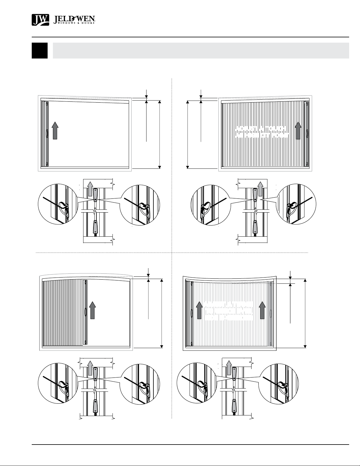
Wind & Operation Tips
The screen is tted with ‘tensioning’ cords located within the guide
channel & track that not only provide stability to the screen, but control
the vertical orientation of the handlebar and help prevent the mesh from
blowing out of the in windy conditions. Should the blow out gently retract
the screen and the mesh should self-feed back into the, if not simply pop
the mesh back by hand.
On large openings the screen mesh acts like a sail. In gusty or windy
conditions it is recommended to keep the screen retracted to reduce
possibility of damage occurring. If the mesh is damaged or a tension cord
breaks, the screen will need to be replaced. The screen has been designed
to be interchangeable with a replacement. It is recommended you contact
the original installer.
Servicing
If the mesh is damage or a tension cord breaks, the screen will need to
be replaced. The screen has been designed to be interchangeable with
a replacement screen assembly which is reinstalled into the existing
channels. We recommend contacting the original installer to have the
screen cut to size and retted.

Installation Instructions
for Siteline®Low-Friction Glider™Wall System Brio®Pleated Screens Distributed by
JELD-WEN®(JII-90048)
©2020 JELD-WEN, Inc. This publication and its contents are owned by or licensed to JELD-WEN, Inc. or its afliates or third parties, and are protected by copyright, trademark, and other laws. Unauthorized use
or duplication is prohibited. JELD-WEN reserves the right to change product specications without notice. Please visit our website at jeld-wen.com for current information.
All rights reserved.
JII-90048 3/20
Distributed by:
This manual suits for next models
1
Table of contents
Popular Projection Screen manuals by other brands

Stewart Filmscreen
Stewart Filmscreen C installation instructions

Contro l4
Contro l4 C4-TSWMC5-EG-WH installation guide

Grandview
Grandview GVFA100V installation manual

LG
LG LAA015FL7B1 installation guide

Celexon
Celexon HomeCinema Electric Tension screen Operation manual

Grandview
Grandview Edge R2 Series user manual