Grizzly G0640X User manual

MODEL G0640X
17" WOOD/METAL BANDSAW
OWNER'S MANUAL
COPYRIGHT © JANUARY, 2008 BY GRIZZLY INDUSTRIAL, INC.
WARNING: NO PORTION OF THIS MANUAL MAY BE REPRODUCED IN ANY SHAPE
OR FORM WITHOUT THE WRITTEN APPROVAL OF GRIZZLY INDUSTRIAL, INC.
#TR9556 PRINTED IN TAIWAN


Table of Contents
INTRODUCTION ............................................... 2
Foreword ........................................................ 2
Contact Info ................................................... 2
Functional Overview ...................................... 2
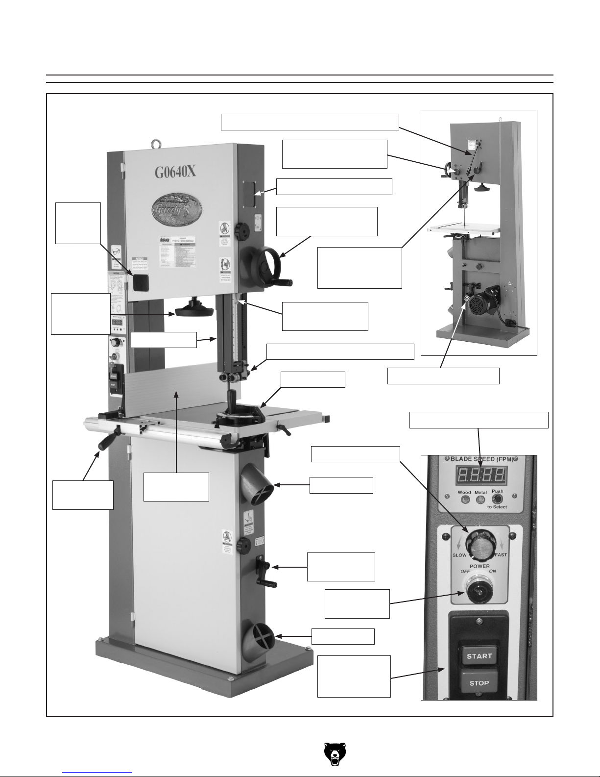
Identification ................................................... 3
Machine Data Sheet ...................................... 4
SECTION 1: SAFETY ....................................... 6
Safety Instructions for Machinery .................. 6
Additional Safety Instructions for Bandsaws . 8
SECTION 2: CIRCUIT REQUIREMENTS ........ 9
220V Operation .............................................. 9
SECTION 3: SETUP ....................................... 10
Setup Safety ................................................ 10
Items Needed for Setup ............................... 10
Unpacking .................................................... 10
Inventory ...................................................... 11
Clean Up ...................................................... 12
Site Considerations ...................................... 12
Moving & Placing Bandsaw ......................... 13
Mounting ...................................................... 13
Assembly ..................................................... 14
Blade Tracking ............................................. 17
Test Run ...................................................... 18
Blade Tensioning ......................................... 19
Adjusting Blade Guides ............................... 20
Adjusting Support Bearings ......................... 21
Adjusting Positive Stop ................................ 22
Aligning Table .............................................. 23
Aligning Fence ............................................. 24
Miter Gauge ................................................. 24
SECTION 4: OPERATIONS ........................... 25
Operation Safety .......................................... 25
Guide Post ................................................... 25
Quick Release Blade Tension ..................... 26
Table Tilt ...................................................... 26
Blade Terminology ....................................... 27
Blade Selection ............................................ 27
Blade Breakage ........................................... 29
Blade Care & Break-In ................................. 29
Blade Changes ............................................ 30
Blade Speed ................................................ 31
SECTION 5: WOOD CUTTING ...................... 32
Workpiece Inspection .................................. 32
Cutting Tips .................................................. 32
Ripping ......................................................... 33
Crosscutting ................................................. 33
Resawing ..................................................... 34
Stacked Cuts ............................................... 35
Cutting Curves ............................................. 35
Cutting Circles ............................................. 35
SECTION 6: METAL CUTTING ...................... 36
Workpiece Inspection .................................. 36
Cutting Tips .................................................. 36
Choosing Blades and Speeds ..................... 37
Metal Chip Inspection Chart ........................ 38
SECTION 7: ACCESSORIES ......................... 39
SECTION 8: MAINTENANCE ......................... 41
Schedule ...................................................... 41
Cleaning ....................................................... 41
Wheel Brush ................................................ 41
Lubrication ................................................... 41
Redressing Rubber Tires ............................. 43
SECTION 9: SERVICE ................................... 44
Troubleshooting ........................................... 44
Replacing V-Belts ........................................ 46
Adjusting Wheel Brush ................................ 46
Wheel Alignment .......................................... 47
Shimming Table ........................................... 49
Blade Lead ................................................... 49
Adjusting Tension Lever .............................. 50
Electrical Component Wiring ....................... 51
Wiring Diagram ............................................ 52
Main Parts .................................................... 53
Fence & Blade Guides ................................. 54
Parts List ...................................................... 55
Labels .......................................................... 58
WARRANTY AND RETURNS ........................ 61

-2- G0640X 17" Wood/Metal Bandsaw
INTRODUCTION
Foreword
We are proud to offer the Model G0640X 17"
Wood/Metal Bandsaw. This machine is part of a
growing Grizzly family of fine machinery. When
used according to the guidelines set forth in this
manual, you can expect years of trouble-free,
enjoyable operation and proof of Grizzly’s com-
mitment to customer satisfaction.
The specifications, drawings, and photographs
illustrated in this manual represent the Model
G0640X as supplied when the manual was pre-
pared. However, owing to Grizzly’s policy of con-
tinuous improvement, changes may be made at
any time with no obligation on the part of Grizzly.
For your convenience, we always keep current
Grizzly manuals available on our website at
www.grizzly.com. Any updates to your machine
will be reflected in these manuals as soon as they
are complete.
If you have any comments regarding this manual,
please write to us at the address below:
Grizzly Industrial, Inc.
C/O Technical Documentation Manager
P.O. Box 2069
Bellingham, WA 98227-2069
Email: [email protected]
We stand behind our machines. If you have any
service questions or parts requests, please call or
write us at the location listed below.
Grizzly Industrial, Inc.
1203 Lycoming Mall Circle
Muncy, PA 17756
Phone: (570) 546-9663
Fax: (800) 438-5901
E-Mail: [email protected]
Web Site: http://www.grizzly.com
Contact Info
The bandsaw is one of the most versatile cutting
tools in the shop and is capable of the following
cuts:
• Miters and angles
• Compound Angles
• Resaw Cuts
• Rip and Crosscuts
• Curves and Circles
• Stacked Cuts for Duplicate Parts
The blade is a flexible steel band with teeth on
one edge that fits around two aligned wheels with
slightly crowned rubber tires, which help the blade
track in the center of the wheels during opera-
tion.
One wheel stays in a fixed position and is driven
by a motor. The other wheel spins freely and
adjusts toward or away from the fixed wheel,
which controls the tension of the installed blade.
This wheel usually also features a tracking control
that tilts the wheel forward or backward to ensure
the blade rides in the center of the wheel. The
rotation of both wheels pulls the blade downward
toward the table.
When a workpiece is pushed against the mov-
ing blade, the downward force of the blade teeth
scrape across the workpiece and, in effect, cut
it. Blade guides on both sides of the cutting area
keep the blade from flexing or being pushed off
the wheels from the horizontal pressure of the
workpiece while cutting.
Since the purpose of the blade guides is to
provide support while cutting, they should be
as close as possible to the blade; however, the
blade guides should only touch the blade while a
workpiece is being cut, or the constant friction will
reduce the life of the blade. Also the upper blade
guide assembly should be adjusted as close as
possible to the workpiece to provide maximum
support and cover any unused area of the blade
with the blade guard.
Functional Overview

G0640X 17" Wood/Metal Bandsaw -3-
Identification
Blade
Tension
Window
Blade
Tension
Handwheel
Fence Lock
Handle
Blade Tension Window
Blade Guide Height
Handwheel
Upper Blade Guide Assembly
Miter Gauge
4" Dust Port
4" Dust Port
Belt Tension
Crank
Rip Fence
Attachment
Blade Guard
Blade Guide
Height Indicator
Quick Release Blade Tension Lever
Blade Guide
Elevation Lock Knob
Blade Tracking
Knob with Lock
Lever
Belt Engagement Disc
Digital Blade Speed Display
Blade Speed Dial
Main Power
Key Switch
Motor
START/STOP
Switch

-4- G0640X 17" Wood/Metal Bandsaw
Machine Data Sheet

G0640X 17" Wood/Metal Bandsaw -5-

-6- G0640X 17" Wood/Metal Bandsaw
Safety Instructions for Machinery

G0640X 17" Wood/Metal Bandsaw -7-

-8- G0640X 17" Wood/Metal Bandsaw
Additional Safety Instructions for Bandsaws
9. BLADE SPEED. Allow blade to reach full
speed before cutting.
10. MAINTENANCE/SERVICE. All inspec-
tions, adjustments, and maintenance are
to be done with the power OFF and the
plug removed from the outlet. Wait for all
moving parts to come to a complete stop.
11. BLADE CONTROL. Do not attempt to
stop or slow the blade with your hand or
a workpiece. Allow the blade to stop on its
own, unless your machine is equipped with
a brake.
12. UNSTABLE WORKPIECES. Workpieces
that cannot be supported or stablized with-
out a vise should not be cut on a verti-
cal metal-cutting bandsaw, because they
can unexpectedly move while cutting and
entangle the operator's hands into the
blade. Examples are chains, cables, round
or oblong-shaped workpieces, workpieces
with internal or built-in moving or rotating
parts, etc.
13. DUST COLLECTION. Mixing metal cut-
tings with wood dust greatly increases the
risk of fire. Wood dust collectors are not
designed to collect metal. Instead use a
wet/dry vacuum or Shop•Vac to collect
metal cuttings from the bandsaw.
14. WOOD/METAL CONVERSION. Wood
dust on or in the bandsaw may catch fire
if exposed to hot metal cuttings. To reduce
this risk, thoroughly vacuum any wood dust
from inside and outside the bandsaw when
converting bandsaw for metal cutting.
15. EXPERIENCING DIFFICULTIES. If at
any time you are experiencing difficulties
performing the intended operation, stop
using the machine! Contact our Technical
Support Department at (570) 546-9663.
1. BLADE CONDITION. Do not operate with
a dull, cracked, or badly worn blade. Dull
blades require more effort to use and are
difficult to control. Inspect blades for cracks
and missing teeth before each use.
2. HAND PLACEMENT. Never position hands
in line with the cut. Serious personal injury
could occur.
3. GUARDS. Do not operate this bandsaw
without the blade guard in place or with the
doors open.
4. BLADE REPLACEMENT. When replacing
blades, make sure teeth face down toward
the table and the blade is properly ten-
sioned before operating.
5. WORKPIECE HANDLING. Never hold
small workpieces with your fingers during
a cut. Always support/feed the workpiece
with push stick, table support, vise, or
some type of clamping fixture.
6. CUTTING TECHNIQUES. Plan your cuts
so you always cut out of the wood. DO
NOT back the workpiece away from the
blade while the saw is running. If you need
to back the work out, turn the bandsaw
OFF and wait for the blade to come to a
complete stop, and DO NOT twist or put
excessive stress on the blade while back-
ing work away.
7. LEAVING WORK AREA. Never leave the
machine running and unattended. Allow the
bandsaw to come to a complete stop be-
fore you leave it unattended.
8. FEED RATE. Always feed stock evenly
and smoothly. DO NOT force or twist blade
while cutting, especially when sawing small
curves.

G0640X 17" Wood/Metal Bandsaw -9-
SECTION 2: CIRCUIT REQUIREMENTS
220V Operation
Full Load Amperage Draw
This machine draws the following amps under
maximum load:
Amp Draw ................................................8 Amps
Power Supply Circuit Requirements
You MUST connect your machine to a grounded
circuit that is rated for the amperage given below.
Never replace a circuit breaker on an existing cir-
cuit with one of higher amperage without consult-
ing a qualified electrician to ensure compliance
with wiring codes. If you are unsure about the
wiring codes in your area or you plan to con-
nect your machine to a shared circuit, consult
a qualified electrician.
Minimum Circuit Size .............................15 Amps
Extension Cords
Using extension cords may reduce the life of the
motor. Instead, place the machine near a power
source. If you must use an extension cord:
• Use at least a 14 gauge cord that does not
exceed 50 feet in length!
• The extension cord must also have a ground
wire and plug pin.
• A qualified electrician MUST size cords over
50 feet long to prevent motor damage.
Figure 1. NEMA 6-15 plug and receptacle.
Serious personal injury could occur if you
connect the machine to power before com-
pleting the setup process. DO NOT connect
the machine to the power until instructed
later in this manual.
Electrocution or fire could
result if machine is not
grounded and installed in
compliance with electrical
codes. Compliance MUST
be verified by a qualified
electrician!
Power Connection Device
The type of plug required to connect your machine
to power depends on the type of service you cur-
rently have or plan to install. We recommend
using the plug shown in Figure 1.

-10- G0640X 17" Wood/Metal Bandsaw
Wear safety glasses dur-
ing the entire set up pro-
cess!
This machine presents
serious injury hazards
to untrained users. Read
through this entire manu-
al to become familiar with
the controls and opera-
tions before starting the
machine!
SECTION 3: SETUP
Some inventory compo-
nents are very heavy. DO
NOT over-exert yourself
while unpacking, moving,
or installing them—get
assistance.
Setup Safety
The following items are needed to complete the
setup process, but are not included with your
machine:
Description Qty
• Straightedge ............................................... 1
• Level ........................................................... 1
• Another Person for Lifting Help .................. 1
• Forklift ......................................................... 1
• Lifting Strap or Chain (500 lb min. cap.) .... 1
• Lifting Hook or Shackle .............................. 1
• Square ........................................................ 1
• Feeler Gauge 0.016" .................................. 1
• Safety Glasses (for each person) .............. 1
• Wet/Dry Vacuum for Dust Collection ......... 1
• Vacuum Adaptor 4" .................................... 1
• Dust Hose Y-Fitting 4" ................................ 1
• Dust Hose 4" (length as needed) ............... 2
• Hose Clamp 4" ........................................... 4
Items Needed for
Setup
The Model G0640X was carefully packed when it
left our warehouse. If you discover the machine
is damaged after you have signed for delivery,
please immediately call Customer Service at
(570) 546-9663 for advice.
Save the containers and all packing materials for
possible inspection by the carrier or its agent.
Otherwise, filing a freight claim can be difficult.
When you are completely satisfied with the condi-
tion of your shipment, you should inventory the
contents.
Unpacking
This is an extremely
heavy machine. Serious
personal injury may
occur if safe moving
methods are not fol-
lowed. To be safe, you
will need assistance and
a forklift or pallet jack
when moving the ship-
ping crate.

G0640X 17" Wood/Metal Bandsaw -11-
After all parts have been removed from the three
boxes, you should have the following items:
Main Components: (Figure 2 & 3) Qty
A. Bandsaw (not shown) ................................. 1
B. Table .......................................................... 1
C. Miter Gauge ................................................ 1
D. Fence Assembly ......................................... 1
E. Resaw Fence Attachment .......................... 1
F. Front Fence Rail ......................................... 1
G. Rear Fence Rail ......................................... 1
H. Handwheel (not shown) ............................. 1
I. V-Belt A27 (not shown) .............................. 1
J. Scale (not shown) ...................................... 1
Fasteners (and where used): Qty
Hex Bolt M8-1.25 x 100 (Positive Stop) ............ 1
Hex Nut M8-1.25 (Positive Stop) ....................... 1
Cap Screw M6-1 x 20 (Handwheel) .................. 1
Hex Bolts M8-1.25 x 16 (Table) ........................ 4
Lock Washers 8mm (Table) .............................. 4
Flat Washers 8mm (Table) ................................ 4
Cap Screws M6-1 x 25 (Rear Rail) ................... 2
Hex Bolts M6-1 x 20 (Front Rail) ....................... 2
Lock Washers 6mm (Front Rail) ....................... 2
Flat Washers 6mm (Front Rail) ......................... 2
Hex Nut M8-1.25 (Fence Lock Lever) ............... 1
Hex Nut M6-1 (Rail Pad) ................................... 1
Flat Washer 8mm (Attachment Lock Handle) ... 1
Tools & Other Miscellaneous Items: Qty
Hex Wrench 5mm .............................................. 1
Hex Wrench 8mm .............................................. 1
Open End Wrench 10/13mm ............................. 1
Table Pin ........................................................... 1
Table Insert ....................................................... 1
Rail Pad M6-1 x 18 (attaches to fence) ............ 1
Fence Lock Lever M8-1.25 x 22 ....................... 1
Fence Attachment Lock Handle M8-1.25 x 44 .. 1
Fence Attachment T-Slot Nut ............................ 1
Figure 2. Bandsaw components.
BC
D
Figure 3. Fence components.
G
E
D
F
If any nonproprietary parts are missing (e.g. a
nut or a washer), we will gladly replace them, or
for the sake of expediency, replacements can be
obtained at your local hardware store.
NOTICE
Some hardware/fasteners on the inventory
list may arrive pre-installed on the machine.
Check these locations before assuming that
any items from the inventory list are miss-
ing.
Inventory

-12- G0640X 17" Wood/Metal Bandsaw
The unpainted surfaces are coated with a waxy
oil to prevent corrosion during shipment. Remove
this protective coating with a solvent cleaner
or degreaser shown in Figure 4. For thorough
cleaning, some parts must be removed. For opti-
mum performance from your machine, clean
all moving parts or sliding contact surfaces.
Avoid chlorine-based solvents, such as acetone
or brake parts cleaner that may damage painted
surfaces. Always follow the manufacturer’s instruc-
tions when using any type of cleaning product.
Clean Up
Gasoline and petroleum
products have low flash
points and can explode
or cause fire if used to
clean machinery. DO
NOT use these products
to clean the machinery.
Many cleaning solvents
are toxic if inhaled.
Minimize your risk by only
using these products in a
well ventilated area.
G2544—Solvent Cleaner & Degreaser
A great product for removing the waxy shipping
grease from your machine during clean up.
Figure 4. Cleaner/degreaser available from
Grizzly.
Floor Load
Refer to the Machine Data Sheet for the weight
and footprint specifications of your machine.
Some residential floors may require additional
reinforcement to support both the machine and
operator.
Placement Location
Consider existing and anticipated needs, size of
material to be processed through each machine,
and space for auxiliary stands, work tables or
other machinery when establishing a location for
your new machine. See Figure 5 for the minimum
working clearances.
Children and visitors may be
seriously injured if unsuper-
vised. Lock all entrances to
the shop when you are away.
DO NOT allow unsupervised
children or visitors in your
shop at any time!
Site Considerations
Figure 5. Minimum working clearances.

G0640X 17" Wood/Metal Bandsaw -13-
Moving & Placing
Bandsaw
This is an extremely heavy machine. Serious
personal injury may occur if safe moving
methods are not followed. To be safe, you
will need assistance and a forklift or a hoist
when removing the machine from the crate.
Use a chain or a lifting strap with a minimum
of 500 lbs. lifting capacity. If the chain or
lifting strap breaks, serious personal injury
may occur.
Figure 6. Lifting the bandsaw.
Special care should be taken when moving this
bandsaw. Only use the following methods to lift or
move this bandsaw.
To move and place the bandsaw:
1. Use a forklift to move the bandsaw on the
pallet near its final location.
2. Unbolt the bandsaw from the pallet.
3. Place the lifting hook through the eye bolt
(Figure 6) that is located on top of the
machine.
4. Carefully lift the machine and place where
desired.
We recommend mounting your new machine to
the floor. Because floor materials may vary, floor
mounting hardware is not included. You may also
mount your machine to a mobile base (such as
shown in Figure 7) with wheel locking or wheel
retracting capabilities that prevent rolling when
not in use.
Mounting
Figure 8. Typical concrete mounting fasteners.
Lag Shield
Lag Bolt
Anchor Stud
Bolting to Concrete Floors
Lag shield anchors with lag bolts (Figure 8) and
anchor studs are two popular methods for anchor-
ing an object to a concrete floor. We suggest
you research the many options and methods for
mounting your machine and choose the best that
fits your specific application.
Figure 7. Model G7315 Shop Fox mobile base.

-14- G0640X 17" Wood/Metal Bandsaw
Assembly
To assemble the bandsaw:
1. Thread an M8-1.25 hex nut half way up the
length of the included M8-1.25 x 100 hex bolt
(the longest one in the hardware bag).
2. Thread the M8-1.25 x 100 hex bolt (otherwise
known as the "Positive Stop Bolt") into the
casting near the trunnion base, as shown in
Figure 9.
Note: The positive stop bolt acts as a table
stop, which makes it easy to bring the table
back to 90° after tilting it.
Figure 9. Positive stop bolt installed.
Positive
Stop
Bolt
Table Trunnion
Figure 11. Quick release tension lever.
Tighten
Loosen
4. Loosen blade tension by rotating the quick
release tension lever clockwise as shown in
Figure 11.
3. Slide the handwheel onto the shaft, as shown
in Figure 10, and thread the M6-1 x 20 cap
screw through the side of the handwheel and
against the shaft to secure the handwheel in
place.
Figure 10. Handwheel installed.
Handwheel
5. Adjust the upper and lower blade guides
away from the blade. Refer to Adjusting
Blade Guides on Page 20 for more details.
The table is heavy. To
reduce the risk of injury
when lifting, have another
person help you during
the next step.
The saw blade is very
sharp and can easily cut
bare hands. Wear heavy
leather gloves whenever
handling.
6. Open the upper and lower wheel covers, and
slide the blade off of both wheels.
7. Place the table onto the trunnion and posi-
tion it so the mounting holes in the table are
aligned with those on the trunnion.

G0640X 17" Wood/Metal Bandsaw -15-
8. Attach the table to the trunnion with four M8-
1.25 x 16 hex bolts, 8mm lock washers, and
8mm flat washers.
9. With the blade teeth pointing downward, slide
the blade through the table slot.
10. Slide the blade through the upper and lower
blade guides, and mount it over the upper
and lower wheels.
11. Tighten the quick release tension lever, then
install the table insert and table pin.
Note: Keep the upper and lower blade guides
adjusted away from the blade until the blade
tracking and tension have been adjusting
during later steps.
12. Adjust the blade tension until the mark on the
blade tension scale is between 4 and 6.
13. Attach the rear rail to the table with the two
M6-1 x 25 cap screws (see Figure 12).
15. Install an M8-1.25 hex nut on the fence lock
lever, then thread the handle into the fence
assembly (Figure 13). Tighten the hex nut
against the fence pivot block to secure the
handle.
16. Thread the M6-1 hex nut onto the rail pad,
then thread the rail pad into the underside of
the back end of the fence (see Figure 14).
17. Place the 8mm flat washer on the fence
attachment lock handle, slide it through the
hole in the fence, then thread the T-slot nut
onto the end of the lock handle threads.
14. Attach the front rail with the M6-1 x 20 hex
bolts, lock washers, and flat washers as
shown in Figure 12.
Figure 13. Handle installed on fence assembly.
Pivot Block
Fence Lock Lever
M8-1.25
Hex Nut
Figure 14. Installed rail pad on back end of
fence.
Rail Pad
M6-1
Hex Nut
Figure 12. Rail installation.
Rear View
Front View

-16- G0640X 17" Wood/Metal Bandsaw
19. Pull the fence lock lever up and place the
fence assembly on the front rail, as shown in
Figure 16.
Figure 16. Correctly installed fence.
20. Adjust the rail pad against the rear rail until
there is an even gap between the bottom of
the fence and the table, then tighten the rail
pad hex nut against the fence to secure the
rail pad in place.
21. Slide the fence against the blade.
22. Place a straightedge across the table and line
it up over the fence scale indicator line.
23. Move the fence out of the way and carefully
make a pencil mark on the front rail, using
the straightedge as a guide. This mark will be
used to line up the zero mark on the scale in
the next step.
18. Slide the resaw fence over the T-slot nut,
as shown in Figure 15, so the T-slot nut fits
inside the channel of the resaw fence, then
tighten the lock handle.
Figure 15. Attaching resaw fence to standard
fence.
T-Slot
Nut
Lock Handle
Resaw Fence
25. Fit a 4" dust hose or 4" adapter over each
dust port and secure in place with hose
clamps, as shown in Figure 17.
Note: A tight fit is necessary for proper per-
formance.
Figure 17. Dust hoses attached to dust ports.
24. Carefully install the scale on the front fence
rail, so the 0" mark on the scale lines up with
the pencil mark made in Step 23. Accuracy in
this step is extremely important.
Note: After adhering the scale, you can
adjust the position of the front rail slightly in
either direction to increase the accuracy.
This saw creates substantial amounts of fine
dust while operating. Failure to use a vacuum
system can result in respiratory illness.
26. If cutting both wood and metal, connect this
machine to a shop vacuum rather than a
dust collector. Most dust collectors are not
designed to capture metal shavings and
doing so may lead to a fire from wood dust
contacting hot metal cuttings or sparks from
metal pieces hitting a dust collector impeller.
Mixing wood dust and metal cuttings may
cause a fire. Do not collect metal shavings in
a regular wood dust collector. Instead use a
shop vacuum to collect metal cuttings.

G0640X 17" Wood/Metal Bandsaw -17-
Blade Tracking
Serious personal injury
can occur if the machine
starts while your hand
is touching the bandsaw
wheel during tracking
adjustments. Disconnect
power from the bandsaw
before performing blade
tracking adjustments.
"Blade Tracking" refers to how the blade rides on
the wheels. When tracking correctly, the blade
rides in the center of the rim part of the wheels.
Blade tracking is primarily controlled by adjust-
ing the upper wheel tilt. Tracking the blade in
this manner is referred to as "Center Tracking,"
because you tilt the wheel until the blade rides in
the center.
Another way to track the blade is known as
"Coplanar Tracking." Coplanar tracking involves
aligning the wheels so they are parallel and
aligned (see Wheel Alignment on Page 47).
When wheels are coplanar, vibration and heat are
reduced during operation.
The wheels on the Model G0640X are factory
aligned, so center tracking is the only adjustment
that needs to be performed during setup.
To center track the blade:
1. DISCONNECT BANDSAW FROM POWER!
2. Make sure the upper and lower blade guides
are adjusted away from the blade.
3. Engage the quick tension lever and turn the
blade tension handwheel until the tension
scale (Figure 18) reads between 4 and 6.
Blade Centered
on Peak of Crown
Blade
Centered
on Wheel
CENTER TRACKING
Wheel
Figure 19. Center tracking profiles.
The cast iron spokes may have sharp edges
and the blade teeth may extend beyond the
edge of the wheel, creating a laceration haz-
ard. In the next step, be careful when turn-
ing the wheel by hand.
4. Spin the upper wheel by hand at least three
times and watch how the blade rides on the
crown of the wheel. Refer to Figure 19 for an
illustration of this concept.
—If the blade rides in the center of the
upper wheel and is centered on the peak
of the wheel crown, then the bandsaw is
already tracked properly and no further
adjustments are needed at this time.
—If the blade does not ride in the center
of the upper wheel and is not centered
on the peak of the wheel crown, then
continue with the following steps.
Figure 18. Blade tensioning controls.
Blade Tension
Handwheel
Blade Tension
Scale

-18- G0640X 17" Wood/Metal Bandsaw
Figure 20. Blade tracking controls.
Blade Tracking
Knob
Lock Lever
5. Loosen the lock lever shown in Figure 20 so
that the blade tracking knob can rotate.
NOTICE
Changes in the blade tension may change
the blade tracking.
6. Spin the upper wheel with one hand and
slowly rotate the tracking control knob with
the other hand to make the blade ride in the
center of the bandsaw wheel tire.
7. Close the upper wheel cover.
8. Fine tune the blade tracking (as instructed
in the following Test Run procedure) while
the bandsaw is running, then tighten the lock
lever attached to the blade tracking knob.
If you still cannot remedy a problem, contact our
Tech Support at (570) 546-9663 for assistance.
To test run the machine:
1. Make sure you have read the safety instruc-
tions at the beginning of the manual and that
you have followed all previous setup instruc-
tions in this section.
2. Make sure all tools and objects used during
setup are cleared away from the machine
and that the wheel covers are closed and
latched.
3. Connect the machine to the power source.
4. Lower the upper blade guide assembly to
approximately 1" over the table.
5. Turn the variable speed dial counterclock-
wise (toward the SLOW side) all the way.
6. Turn the power key switch to the ON posi-
tion.
7. Press START, allow the bandsaw to run for
two seconds, then press STOP. This will give
the blade enough time to start tracking off the
wheel if the tracking is set incorrectly.
8. Look through the blade tracking window (see
Figure 21) and notice the position of the
blade on the wheel.
Figure 21. Blade tracking window.
Test Run
Once the assembly is complete, test run your
machine to make sure it runs properly and is
ready for regular operation.
The test run consists of verifying the following:
1) The motor powers up and runs correctly, and
2) the key switch shuts off power power to the
machine when in the off position.
If, during the test run, you cannot easily locate
the source of an unusual noise or vibration,
stop using the machine immediately, then review
Troubleshooting on Page 44.
Other manuals for G0640X
2
Table of contents
Other Grizzly Saw manuals

Grizzly
Grizzly G0734 User manual

Grizzly
Grizzly G0661 User manual

Grizzly
Grizzly G0478 Quick start guide

Grizzly
Grizzly G0941 User manual

Grizzly
Grizzly Extreme Series User manual

Grizzly
Grizzly G4030 User manual

Grizzly
Grizzly T10824 User manual

Grizzly
Grizzly G0502 User manual

Grizzly
Grizzly G0636X User manual

Grizzly
Grizzly EXTREME G0513X2 User manual

Grizzly
Grizzly G9742 User manual

Grizzly
Grizzly G0820 User manual

Grizzly
Grizzly G8122 User manual

Grizzly
Grizzly G1023RLX User manual

Grizzly
Grizzly T10874 User manual

Grizzly
Grizzly G0536 User manual

Grizzly
Grizzly H8145 Quick start guide

Grizzly
Grizzly G0561 User manual

Grizzly
Grizzly G0570 User manual

Grizzly
Grizzly G0665 User manual