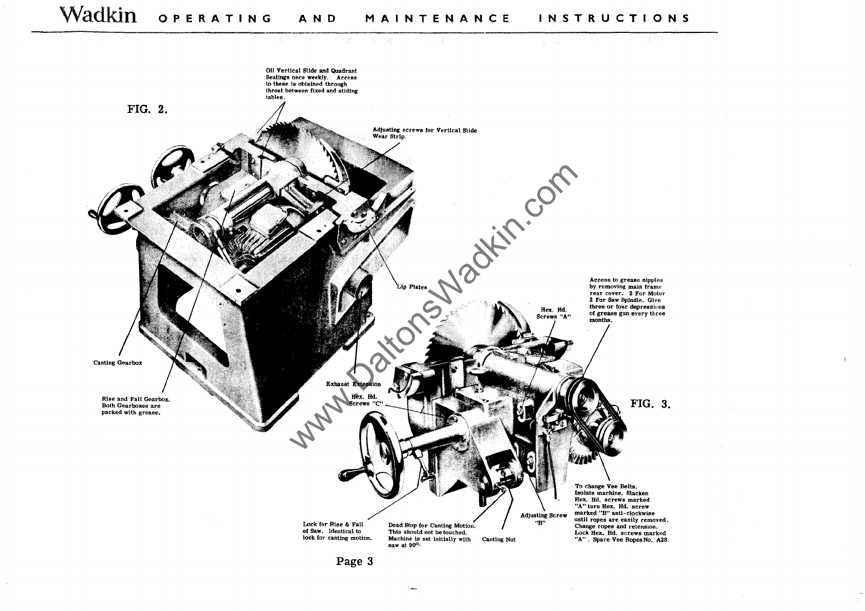
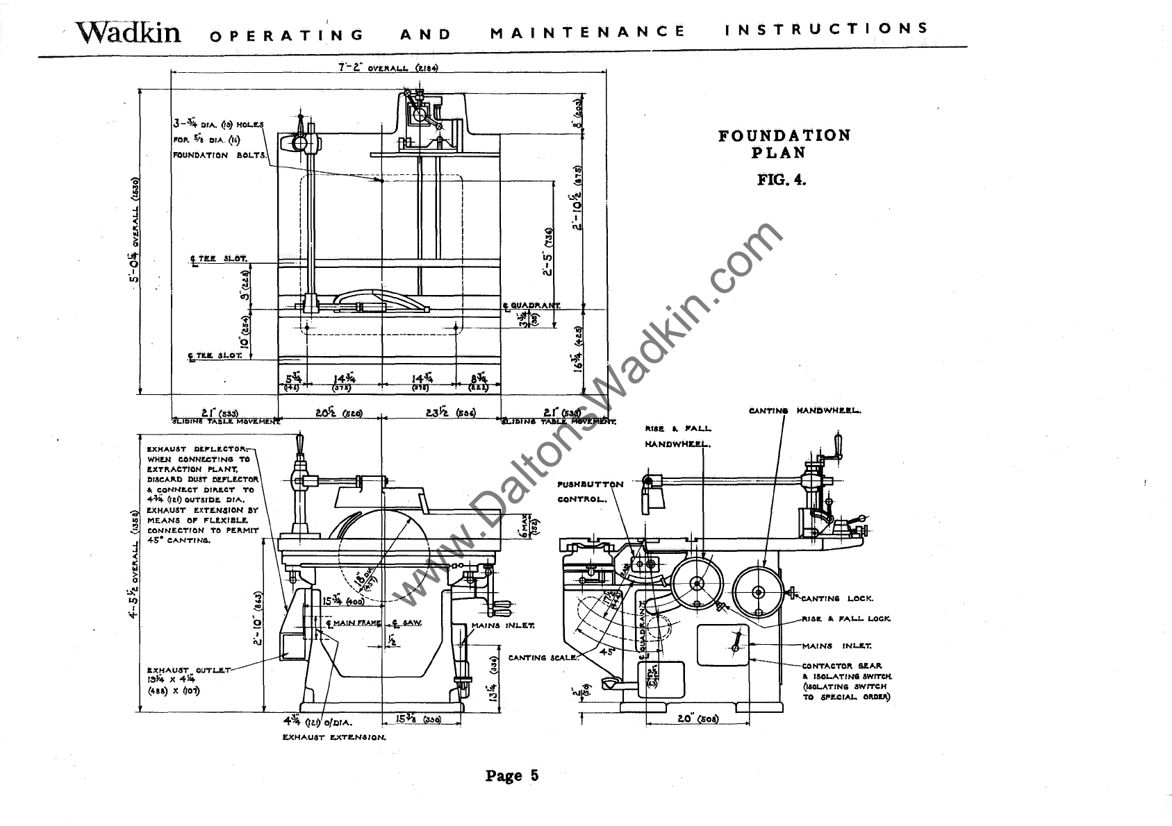
manuals.online logo
Brands
  1. Home
  2. •
  3. Brands
  4. •
  5. Wadkin
  6. •
  7. Saw
  8. •
  9. Wadkin PP Series User manual

Wadkin PP Series User manual

"WADKIN"
DIMENSION
SAW
TYPE
IIPP"
INSTRUCTION
BOOK
NO:
987
www.DaltonsWadkin.com
Waakin
OPERATING
AND
MAINTENANCE
INSTRUCTIONS
Wadkin
DIMENSION
SAW
TYPE
P.
P.
PRINCIPAL
DIMENSIONS AND CAPACITIES
:-
Standard
size
of
saw
..
Maximum
depth
of
cut
.
Depth
of
cut
with
saw
canted
to
45°
Throat
opening
between
fixed
and
sliding
tables
..
Saw
cants
up to
""
..
"
""
..
"
".
....
...
....
.. ..
Maximum
distance
between
saw
and
ripping
fence
on
standard
table
..
"
..
"
.. ..
..
..
Will
crosscut
on
standard
table
with
saw
at
90
0
••
Length
cut
off
using
stop
on
mitre
fence
..
Ripping
fence
cants
up to
..
Horse
power
of
motor..
..
Speed
of
saw
spindle
50
and
60
cycles
.
.'
Details
included
with the
machine.
One
pair
saw
collars
and
nUt.
Motor
and
control
gear.
Saw
guard
and
riving
knife.
Single
mitre
fence
with
stop
bar
and
stop.
Page
1
18"
450
mm.
5!"
140
mm.
3.
7/8"
100
mm.
6"
150
mm.
45
0
45
0
30"
760
mm.
5!fi x
29!"
140 x 750
mm.
1
if
X
36"
25 x 915
mm.
36"
915
mm.
45
0 450
5 5
2800
r.p.m.
2800
r.p.m.
Canting
Ripping
fence.
Set
of
spanners.
Tin
of
lubricant.
www.DaltonsWadkin.com
Wadkin
OPERATING
FIG.!.
Dust
Deflector.
----
Foot
Brake
embodying
Automatic
Electric
Stop
Switch
for
Motor.
AND
MAINTENANCE
Page
2
INSTRUCTIONS
Locking handle
"A"
Handwheel to
cant
the
saw.
Handwheel
to
raise
and
lower
the
saw.
www.DaltonsWadkin.com
Wadkin
OPERATING
AND
MAINiENANCE
FIG. 2.
Rise
and
Fall
Gearbox.
Both Gearboxes
are
packed with
grease.
011
Vertical
Slide and Quadrant
Seatings
once
weekly.
Actess
to these
is
obtained through
throat
between fixed
and
sliding
tables.
Lock for
Rise
"
Fall
of
Saw. Identical to
lock
for canting motion.
Page
3
Dead Stop
for
Canting Motion.
This
should not
be
touched.
Machine
Is
set
initially
with Canting Nut
saw at
90
0•
INSTRUCTIONS
Hex. Bd.
Access
to
grease
nipples
by removing main frame
rear
cover. 2 For Motor
2
For
Saw Spindle. Give
three
or
four
depressions
of
grease
gun
every
three
months.
FIG. 3.
To change Vee Bella.
Isolate machine. Slacken
Hex.
Hd.
screws
marked
"A"
turn Hex.
Hd.
screw
marked
"BH
anti-clockwise
until
ropes
are
easily
removed.
Change ropes
and
retension.
Lock Hex.
Hd.
screws
marked
"A"
. Spare Vee RopesNa. A28,
www.DaltonsWadkin.com
Wadkin
OPERATING
AND
MAINTENANCE
INSTRUCTIONS
REMOVAL
OF
SAW
SPINDLE CARRIAGE.
Isolate
machine
electrically.
Remove
guard
and
fence
assemblies.
Remove
complete
sliding
table
unit by
removing
locking
handles
marked
"A"
Fig.
1
and
lifting
table
clear
of tenon
marked
"B"
Fig.
1
and
brackets
marked
"C"
Fig.
1. Remove
tee
slot
filling in
strips
from
main
table
and knock through two dowel
pins
from
the top
and
remove
four hexegon
head
screws
from
underside
of body flange,
lift
table
clear.
Remove
electrical
leads
to
motor
and
brake
cable
from
brake
shoe.
Remove
four
hexegon
head
screws
marked
"c"
Fig. 3
from
each
arm
carrying
handwheel
these
can now
be
withdrawn
from
both
gearboxes.
Wedge
saw
spindle
carriage
in 90
degrees
position
using
wood
blocks,
then
remove
canting
gearbox
pivot
pin,
gearbox
complete
with canting
screw
can
now
be
withdrawn
from
canting nut
see
Fig.
3.
Remove
dust
deflector
and
exhaust
extension,
canting
pOinter
from
lip
plate
and
remove
lip
plates
see
Fig.
2. Spindle
carriage
can now
be
removed
from
its
pOSition
in
the
main
frame.
Reassemble
in
the
reverse
order
of
the above.
Maintenance
that
can
be
carried
out with
saw
spindle
carriage
removed.
Changing of
motor.
Changing of
spindle
bearings,
see
special
instructions.
Page
6.
Adjustment
to
wear
strip
of
vertical
slide.
Page
4
www.DaltonsWadkin.com
WaOKin
OPERATING
AND
MAINTENANCE
o
l§
~
~
~
o
.1
U)
J-~
OIA.
Q&)
H01.U
1'01'.
sia
01A..
(,,)
FOUNDATION
aOloTS.
IDJ
MOV'!'ME.
ItXHAUST
DItP"1.ItCTO!'..
WHI!.N
CDNNECTINEI TO
r;XT!'.ACTION
PLANT,
DISCA!'.D DUST /If.l'lor;CTOR
&.
cONNItCT
OII'.r;CT
Ta
<!--¥.4.
<ltl) OUTSIDE.
OIA.
-1:----------
14~
a
..
I!.XHAUST
ItXT£.N,sION
ay
..
MEANS
01'
P"1..!'l(llIlol!.
!2
CONNECTION
TO
pr;
...
MIT
l-+F=l~:J...LfII-_--U-fL""':~
____
-..l-'~'~~::
j
<!-s'
CANTINEI.
-
-<
:i
>
o
'.:t;'
U)
I
.,..
~s~~A~~l&t.
QUT1.I!.T
(U8) le
(roi)
J
i\J
Page
5
..
r-
..
,~
o
1\181t
..
Jl"AI..J..
HANDWHUJ...
loO"
soa
INSTRUCTIONS
FOUNDATION
PLAN
FIG. 4.
CANT/Ne
HANDWHUJ...
Rllllt
..
FALl..
LOCK.
CONTACTOR
6ftA!'.
&.
ISOJ..ATINEI SWITCH.
(UOloATING
SWITCH
TO 6Pl!.CIAI.. aMI!.!'.)
www.DaltonsWadkin.com
Wadkin
OPERATING
AND
MAINTENANCE
INSTRUCTIONS
SECTION THROUGH
BELT
DRIVEN
SPINDLE
.
..
'c'
r~orA.
WHIT.
THRC.i~p.r.
~~~~~~~~~~~~~~~~~~~
__
~~~/
L...
HAND.
FIG.
5.
~z.
CrA.
CRfVrNG
PESS.
To
remove
the
spindle
without
removing
saw
spindle
carriage,
cant
saw
to
approx.
300.
Remove
sliding
table
(see
page
4).
Remove
vee
ropes
see
Fig.
3. Remove
spindle
nut,
saw
&
saw
flanges.
Remove
ball
bearing
locknut
marked
"A".
This
has
a
right
hand
thread.
Remove
pulley,
end
cap
marked
"B",
this
has
four
countersunk
head
screws,and
driving
key.
Remove
end
cap
marked
"C"
this
has
capscrews.
Spindle
can
now
be
knocked out
from
rear
end
using
a
piece
of wood
or
soft
metal
(Brass,
Copper,
Lead).
Page
6
www.DaltonsWadkin.com
Wadkin
OPERATING
AND
MAINTENANCE
INSTRUCTIONS
With the
spindle
removed
rear
bearing
can
be
lightly
tapped
out
of
its
housing. To
change
frent
bearing,
remove
locknut
marked
"0"
this
has
a
right
hand
thread,
and
lightly
tap off
bearing.
To
Reassemble.
Before
assembly
clean
out
all
old
lubricant,
assemble
in
the
reverse
order
of
the
previous
mentioned
procedure,
ensuring
that
no
dirt
or
grit
enters
the
bearings
or
housings.
Smear
the
bearings
with Wadkin
ball
bearing
grease,
grade
L. 6. When
fitting
ball
bearings
do
not
hammer
the
races
into
position
but
give
gentle
taps
with a
soft
rod
all
round
the
periphery.
The
inner
race
should
be
a good
push-fit
on the
spindle
and
the
outer
race
a good
sliding-fit.
BALL
BEARING
LIST
One SKF 6309 Saw
spindle
front
bearing.
One SKF 1306 Saw
spindle
rear
bearing.
Four
SKF
08 Two
each
for
rise
and
fall
and
canting
motions.
Lubrication
see
Figs.
2
and
3.
The
grease
lubricant
recommended
is
Wadkin
Grade
1....
6.
Alternative
grease,
Shell-Mex
& B.
P.
Ltd.
Shell
ALVANIA GREASE 3
Mobil
Oil
Co. MOBILUX GREASE No. 2
Castrol
SPHEEROL
S
For
oil
lubrication,
use
Wadkin
Grade
L.4.
Alternatively
Shell
Mex &
B.
P.
Ltd.
Mobil
Oil
Co.
Castrol
Shell
VITREA OIL 33
Mobil VACTRA
OIL
(heavy
medium)
PERFECTO.
NN.
THOROUGHLY CLEAN DOWN MACHINE WEEKLY.
Page
7.
www.DaltonsWadkin.com
Wadkin
OPERATING
AND
MAINTENANCE
INSTRUCTIONS
FOOT
OPERATED
BRAKE ADJUSTMENT
Grubscrew
marked
"A" Fig. 6
is
initially
set
to
depress
micro-switch
when foot pedal
is
operated
to
its
full extent.
Failure
of
brake
pedal to
return
will
prevent
machine being
started,
check
spring
for
fatigue and
replace
if
necessary.
To
replace
micro-switch;
isolate
machine,
remove
switch, disconnect
electrical
leads,
connect new
switch and
replace
switch on facing.
Start
machine
and
ensure
that when
brake
pedal
arm
is
depressed
to
its
full extent the
micro-switch
is
operated
by
the
grubscrew
marked
"A".
FENCES, TABLE AND GUARDS.
"A"
To
set
canting ripping fence
for
cutting. Move fence to
approximate
position
required.
Operate
first
lock by
rotating
clockwise, fine
adjust
to obtain
correct
dimension
required.
Operate
secondary
lock, this
also
squares
fence to dovetail groove. To unlock fence
operate
first
lock
in
anti-clockwise
direction
until dead stop
is
reached,
secondary lock need not be
operated.
CANTING RIPPING
FENCE
LOCKING ADJUSTMENT
Should the fence
secondary
lock not
operate
the two hexegon head
screws
(on the
right
hand
side
of the fence
base)
should be
slackened
off and
the
three
grubscrews
rotated
clock-
wise
each
by the
same
amount until
the
eccentric
secondary
lock holds
the fence
in
the
required
position
after
operating
the
first
lock.
Fig.
7.
Canting
lock.
Fence
pitching
screws
Secondary
lock.
Page
8
Fence
pOinter locking
grubscrew.
Fine
adjustment.
Eccentric
pivot
pin.
First
lock.
www.DaltonsWadkin.com
WadKin
OPERATING
AND
MAINTENANCE
INSTRUCTIONS
The
ripping fence
is
initially
pitched
.004"
this
is
measured
at
the
front
and
rear
of the
saw,
with
the
saw
fully
raised.
The
dimension
at
the
rear
of
the
saw
being
.
004"
greater
Fig.
8.
Fig. 9.
than
at
the
front
of the
saw.
Should
this
pitching
require
altering
the
grubscrew
locking the
eccentric
pivot
pin,
should be
slackened
off
and
the
eccentric
pivot
pin
turned
so
as
to
increase
or
decrease
the pitching.
To
adjust
the fence
pointer
measure
dimension
between
set
of
saw
nearest
fence and fence
plate,
then
slacken
off pOinter locking
grubscrew,
set
pointer
to
dimension
obtained
between Saw
set
and
fence,
lock
pointer
in
position.
DOUBLE MITRE
FENCE.
Fig.
8.
is
in
two
parts
both
made
to pivot
from
a
central
pin
fixed
in
sliding
table.
Degree
angles
are
marked
on the
table
for
accurately
setting
the
fences,
the
principal
angles
being
positively
located
by
spring
plunger.
Mitres
can
be
cut giving
accurately
squared
frames
when
assembled
a
bar
and
stop
determines
the
exact
length of
material
cut
off.
Front
leaf
is
supplied
as
standard,rear
leaf
optional
extra.
Cross
cutting fence
Fig.
9.
is
used
for
both
square
and
angular
work
and
can
be
used
either
side
of the
saw
in the
table
grooves.
A
bar
and
stop
determines
exact
length of
material
cut
off.
This
fence
is
an
optional
extra.
Page
9
www.DaltonsWadkin.com
Wadkin
OPERATING
FIG. 10
AND
MAINTENANCE
STANDARD
MACHINE
TABLE
Single
mitre
fence
quickly
set
for any
angle.
FIG.
11
LARGER CAPACITY TABLE
Page
10
INSTRUCTIONS
Adjustable
rear
cover
of
guard
to enable fence to
be
set
close
to saw. Also
rear
cover
swings
over
to
permit
fence to be
adjusted
forward
and
set
close
to
saw.
Principal
angle location
for
Mitre
Fence.
Should a
larger
capacity
main
table
be
supplied
of
either
51"
or
72" between
saw
and ripping
fence. A guard
carried
from
the riving knife
will
be
supplied
in addition to standard guard,
16" dia.
saws
can only
be
used
with riving knife guard, and
up
to 30" wide can
be
ripped when
using standard guard and 18"
dia.
saw.
www.DaltonsWadkin.com
WaaKin
OPERATING
AND
MAINTENANCE
INSTRUCTIONS
SLIDING
TABLE
ASSEMBLY
Lock handles
marked
"E"
fig. 6. With
rails
carrying
linear
bearings
in
position,
and hexegon head
screws
holding
adjustable
rail
finger
tight,
lower
table on to
intermediate
slide
and
insert
four pi!,!ces of i"
diameter
steel,
two
each
end, and
adjust
hexegon hole
grubscrew
at
each
end of
table
to
trap
i"
diameter
rods
in pOSition
as
shown
in fig.
1.
Insert
wooden wedges
at
one end of table only and
remove
i"
diameter
rods
at
this
end
as
shown in fig. 2.
Enter
two-thirds
of
the
steel
bridge
between table and
intermediate
slide
as
shown in fig. 3.
Nylon cages and i"
diameter
steel
balls
can
now
be
inserted
by holding
each
ball
in nylon cage with one
finger
of each hand and feeding into
slide-way
as
shown in fig. 4.
With
bridge
piece
complete with nylon
cages
in
position,
remove
wooden wedges and i"
diameter
rods
and
place
in
position
end
retaining
plates
at
each
end of
slide-way.
Traverse
table
to
its
full
extent
in one
direction,
fig. 5, and
using
an
allen
key
adjust
slide
with
screws
marked
"A"
fig.6
until
table
moves
freely
in
this
position.
Now
traverse
table
to
its
full
extent
in the opposite
direction
and
repeat
adjustment
with
screws
marked
"C".
Centralise
table
and
adjust
slide
with
screws
marked
"B".
With
table
traversed
to
its
full
extent
check for
slackness
in the
slide
in both
directions
and
if
necessary
re-adjust
to
eliminate.
Check
sliding
table
for alignment with main
table
by
traversing
table
to
its
full extent and checking
with
straight
edge
across
main and sliding
tables;
repeat
this
operation
at
the
opposite
end. Should
sliding
table
need
re-aligning
with main
table,
first
remove
dowel
pins
in
brackets
marked
"D",
slacken
hexegon
head
screws
and
adjust
table
in
required
direction
as
shown in fig.
6.
Page
11
www.DaltonsWadkin.com
Wadkin
OPERATING
AND
18
il
RIPPING
SAW FOR
GENERAL
WORK.
PART
No
QSI0.
16"
FLAT
CROSS CUT QS8
16"
HOLLOW GROUND
QS9
18"
HOLLOW GROUND QS12
1 8"
FLAT
CROSS CUT SAW
QSll
14"
HOLLOW GROUND SAW QS33
for
cutting
Bakelite,
Tufnol
and
sinailar
naaterials.
18"
NOVELTY
TYPE
SAW QS84
for
cutting
Plywood.
SPINDLE
AND
PIN
HOLES IN SAWS.
MAINTENANCE
INSTRUCTIONS
SA
WS
FOR
USE
ON
THE
P.
P.
TYPE
DIMENSION
SA
W
The
saws
illustrated
are
specially
manufactured
and
tensiohed
to
run
at
high
speed:
it
is
therefore
recommended
they
are
obtained
from
us.
The
teeth
are
designed
to
give
the
best
possible
finish
to
the
work.
Always
keep
the
teeth
sharp
with
an
even
set
on
both
sides.
Before
putting
a new
saw
to
use
it
must
be
ranged
down when
running
at
normal
speed
and
each
tooth
brought
to a
sharp
cutting
edge.
TUNGSTEN CARBIDE
TIPPED
SAWS
14"
TUNGSTEN CARBIDE
TIPPED
QS174
for
cutting
Plywood,
Hardwood
&
Asbestos.
14"
NOVELTY TUNGSTEN CARBIDE
TIPPED
QS176
for
cutting
Plastics
and
Plywood.
16"
TUNGSTEN CARBIDE
TIPPED
QS175
for
cutting
Hardwoods
and
Plywood.
Page
12
www.DaltonsWadkin.com
Waakin
OPERATING
AND
TWO-KNIFE WEDGE TYPE CIRCULAR
CUTTERBLOCK, PLAIN BORE, Q. R. TYPE.
8"
dia. x
15/16"
thick x
H"bore,Part
No.QR.16.
These
cut
t e r b 10 c ks
are
designed to take
5/32"
up
to
t"
thick
cutters:
this
permits
tungsten
car
bid
e
ti
pP e d
-t---f--t-t---+-
cutters
to be supplied when
necessary.
The
cutters
can be used
for
mouldings
requiring
not
more
than
4"
cutter
projection
when
using
t"
thick
cutters.
Our
standard
VZ
range
of
cutters
can
be
used
in
these
cutterblocks,
also
existing
Whitehill head
cutters.
See Section D
Tools
Catalogue.
mGH
SPEED
STEEL
INSERTED TOOTH
GROOVING
SAWS.
C:::::=:::Jq:j
=:
=:J
,
When enquiring
please
give
width and
maximum
depth of
cut
required.
These
saws
are
used
for
accurate
high
grade
work. They
are
fairly
expens-
ive
and
require
good handling.
They
are
available
in
sizes
from
10"
to
12"
diameter,
and
in
varying
widths on cut.
See Section A
Tools
Catalogue
MAINTENANCE
INSTRUCTIONS
4.1/16"
SQUARE
It"
BORE DOVETAIL CUTTER-
BLOCKS.
2"
LONG.
-m-
These
cutterblocks
are
used
for
longer
runs,
cutters
working
in
pairs;
several
pairs
may
be
mounted
on a
single
block to build
up
mould.
The
cutters
on
these
cutterblocks
have. a
very
good cutting angle. They
are
~"
thick and
are
securely
held
by dovetail
bolts.
It
is
therefore
possible
to have a
large
overhang
allowing deep moulds to be worked
with
safety.
Page
13
,
ITOJ]
'I
I I
I I A
limited
range
of Tungsten
Carbide
Tipped
cutters
are
available. Shaped
cutters
can
be
provided
to
special
order.
For
standard
cutters
see
Section C
of
our
Tools
and
Sundries
Catalogue.
HEAVY
TYPE WOBBLE
SAW
UNIT
ON
SCREWED
SLEEVE
I i :
I I
~
:
~
I
I
J
"1
-
Once
set,
the
saw
and
collars
remain
tightlylockedon
sleeve.
This
type
may
be
set
and
kept
at
its
setting
whennoton
mach-
ine.
It
is
a
self-contained
unit.
A
special
spindle locknut
is
eu-
pplied
with this unit.
12"
Diam.
i"t02i"grooves
See Section A
Tools
Catalogue
www.DaltonsWadkin.com
Waakin
OPERATING
AND
MAINTENANCE
INSTRUCTIONS
EXP
ANDING
GROOVING
SAWS
OR
DAOO
HEADS
12"
Diameter
This
tool
is
recommended
for
gIvmg a
smooth
finish,
both with
and
across
the
grain
in
hard
or
soft
woods.
It
is
made
up
in
sets
aIld
each
set
consists
of
two
outside
cutters,
i"
thick,
and
several
inside
cutters
of
various
thicknesses,
1/16",
i"
or
i"
thick,
so
that
by adding
OUtside
cutter
inside Cutter OUtside
Cuttsr
to
or
taking away, any width of
groove
within
the
range
of the
set,
measured
in
eighths
or
sixteenths
of
an
inch,
can
be
cut.
No.1.
For
grooves
i"
to
ilt
Wide,
rising
by
iths.
No. 3.
For
grooves
i"
to
~"wide,
rising
by
1/16ths.
No. 2.
For
grooves
i"
to
8"
wide,
rising
by
iths.
No.
4.
For
grooves
tit to
1"
wide,
rising
by
1/16ths.
EXPANDING TRENCHING AND GROOVING HEADS
This
type
is
expandable
and
made
in two
sizes
13"
diameter.
Accurate
spaCing
collars
give
the
desired
widthof cut
rising
by
1/16"
up to the
maximum.
It
is
arranged
to give a
shearing
cut
and
provided
with
side
or
spur
cutters
to
produce
clean
cu-
tting. The head
is
mounted on a
loose
sleeve
and
locked
tight
by
a fine
thread
nut. One
sleeve
only
is
l'equired
for
the two
sizes
of head.
Sleeve
for
either
head
P.
P.135
complete
with
special
spindle
nut.
J.
P.
550
for
grooves
i" to
1"
wide
and
H·"
deep
J.
P.
558
for
grooves
1.
1/16"
to
2"
wide
and
1~"
deep
To
iD1niDilse the
throat
between fixed
and
sliding
tables.
bothspacing collar
and
rear
saw
collar
are
removed
ftom
the spindle, Ihls
permits
the trenching
or
grooving head
to be
set
backInto the
main
table as shown
In
the
accomp-
anying photograph.
The
head
illustrated
opposite
can
be
used
with
equal
facility
but
is
not
capable
of
such
fine
adjustment
for
width of
groove
as
the one shown above.
The
widthof
cutis
varied
by changing
the
cutters.
Side
or
spur
cutters
in
addition to the
grooving
cutters
effect
clean
cutting.
Head
J.
P.
215
is
11"
diameter
and
will
groove
~"to
2"
wide
1"
deep.
Page
14
www.DaltonsWadkin.com
Wadkin
OPERATING
AND
MAINTENANCE
INSTRUCTIONS
ELECTRICAL
INSTALLATION
INSTRUCTIONS
The
cabUng between the
motor
and the
control
gear
has
been
carried
out by Wadkin Ltd. ,
and
it
is
only
necessary
to
bring
the
line
leads
to
the
machine
for
it
to
be
put
into
service.
This
should
be
done
as
follows:
1.
Fit
triple
pole
isolating
switch
near
the
machine
unless
it
has
been
supplied
to
special
order
by
Wadkin Ltd. . when
it
will
be
fitted
and connected to the
machine.
2. Connect the
line
lead
to the
appropriate
terminals.
See
diagram
of
connect-
ions.
The
cables
should
be
taken to the
machine
in
conduit
and
secured
to the
control
gear
by locknuts.
3. Connect
solidly
to
earth.
4.
Close
isolating
switch
and
press
start
button.
If
motor
does not
rotate
in
the
right
direction,
interchange
any two incoming
line
leads.
FAILURE TO START
1.
Electric
supply is not
available
at
the
machine.
2,
Fuses
have blown
or
have not
been
fitted.
3.
Isolating
switch
has
not
been
closed.
4.
Lock-off
or
stop
button
has
not
been
released.
5.
Micro
switch
open, due to foot
brake
lever
depressing
switch
(see
separate
foot
brake
adjustment
instructions)
STOPPAGE DURING OPERATION AND FAILURE TO RESTART
1.
Fuses
have blown.
2.
Overloads
have
tripped.
They will
reset
automatically
after
a
short
time
and
the
motor
can
be
restarted
in
the
usual
manner.
ADJUSTMENTS
For
a
finer
overload
setting,
set
the
load
indicator
to a
lower
value
and
vice-versa
for
a
less
fine
setting.
GENERAL
Check
the
earth
connection
from
time
to
time.
Users
are
recommended
to
display
in
an
appropriate
position
in the
maintenance
department
a Wadkin
Electrical
Maintenance
Instruction
Card,
No. 356,
which
is
issued
gratis
on
application.
Page
15
www.DaltonsWadkin.com
Wadkin
OPERATING
AND
MAINTENANCE
D.1149 DIMENSION
SAWBENCH
MODEL
P.
P.
•
See
cl
\Q.carcun
o
_,510
Orro&tke
OVE.RL.OA.CS.
---:::::~~~~
I
"YPE
a.15
~
CON,.,A..C,.O".
I
OL.A."T. Nca
$WITCH
----I
....
C'U"~lED
TO
....
ct
...L.
OR.tnt."
ONLY). L......
---.i.---
.......
INSTALLATION INSTRUCTIONS.
I
_-1
R.E.'iA1N
CONTACT.
INSTRUCTIONS
rNTE.R.L.OC:K
SWITCH.
(O"£""T£O
ay BP\A.KE)
Fit
isolating
switch
near
machine
so
that
the
electrical
gear
may
readily
be
isolated
for inspection
purposes.
Bri~
supply
cables
to
isolating
switch and to
Lt
-L2 -L3
at
contactor through!conduit
which should
be
screwed
into the machine and
secured
by
means
of
locknuts.
Ensure
that the
direction
of
rotation
is
correct
before
putting the machine into
service.
To
reverse
rotation
inter-
change
Lt
& L3
at
contactor.
OPERATING INSTRUCTIONS.
To
start
machine:
close
isolating switch and
press
'start'
button. To
stop
machine:
press
'stop'
button. To lock off
machine:
press
and
turn
'stop'
button,
this
must
be
released
before
a
start
can
be
made.
OVERLOAD.
Should
the
machine
stop
due to
overload,
wait
for
a
short
time
to allow the
coils
to cool then
start
in the
usual
manner.
The
overloads
are
set
at
these Works
at
'M'
for automatic
reset
after
tripping,
if
set
at
'P'
the plunger on the
overload
assembly
should
be
depressed
to
reset.
Page
16
www.DaltonsWadkin.com
.MAINS
SUPPLY
OFF
ON
r-~':~-----,
CONTACTOR
OVERLOADS
I I
L1
I I
~U
1111
1M
lOll A
121.8
,:!IQ.
:1L2
:·:Ir------~-----------
...
BC~
....
--~
~~I-.,~I~~c=.-~I~------~----~
~F
MOTOR
13
I.
-;
3FU
Itl3
_
I
~I
I·
FUSES
I
L
________
....I
ISOLATING
SWlTCHFUSE.
(when
fiUe.d)
111
lL3
lOll
'I'
...
..
STOP
11
~
...
12
.......-..
START
0
-~
13
--
14
BRAKE
SWlTCH.
CONTACTOR.
1M
.
1.
~r
SIMILAR
TO I THIRD
ANGLE
PROJECTION
WADKIN
LTD. LEICESTER
SURFACE FINISH
V - ROUGH
MIC
VV
-FINISH
MIC
~--=-::::IM::..:PE:;:.:R:.::IA=-L
::.:.lI
M:::.:I.:..::TS=----I
DATE
S'G.ID
C
TB
DATE
lA
DESCRIPTION
FRACTIONS ±
1/32"
L-A:::,.LT;..:,..:..;,;No;.:..,.
___
....II_+
_____
---L.=....f-
____
---'L...=.-+=2~9_.4:....·.:...77.:.....J_=__=_!SINGlE
MOTOR
CONTROL
DECIMALS +
'005"
I
I--....:::.::.;M::::ET==R,;;:,IC,..,.L~IM::,..,IT,:;.S~--l
R DRN.
BV
I~
BRAKING
SWITCH
vvv -ROUGHGRIND WHOLE NUMBERS = ± 1 M/M CHKD.
BV
OIRECT~ON-LlNE
STARTING
DECIMALS
=±O'I
M/M
VVVV
-FINISH GRIND
BALL
BEARING LIMITS-SEE LIST
QTV.\MATERIAL
PART No.
D.2156
www.DaltonsWadkin.com
· . . blow away harmful dust,
chips
and
dirt
with
a
Blower
Wadkin
Electric
No
motor
can
run
at
its
maximum
efficiency with its
ventilating
duct
or
control
gear
covered
with
dust
and
dirt.
Sooner
or
later
the
resultant
overheating
will
cause
serious
trouble.
Similarly,
accumulations
of
chips
and
dust,
in
the
mechanical
parts
of
the
machine can
interfere
with
its efficiency. A few
minutes
a
week
for
blowing
down
all
Woodworking
Machinery
will
be
amply
repaid
in
better
and
easier
running,
in
increased
life, and
freedom
from
breakdown.
Blowers
can
be
supplied
for
single
phase
A.C.
or
Direct
Current
for
any voltage
up
to
250.
Please
state
voltage
when
ordering.
www.DaltonsWadkin.com

Other Wadkin Saw manuals

Wadkin BRA 450 User manual

Wadkin

Wadkin BRA 450 User manual

Wadkin 24BSW User manual

Wadkin

Wadkin 24BSW User manual

Wadkin CK90 User manual

Wadkin

Wadkin CK90 User manual

Wadkin AGS400 User manual

Wadkin

Wadkin AGS400 User manual

Wadkin BSW User manual

Wadkin

Wadkin BSW User manual

Wadkin CK90 User manual

Wadkin

Wadkin CK90 User manual

Wadkin BSW 26 inch User manual

Wadkin

Wadkin BSW 26 inch User manual

Wadkin AGS400 User manual

Wadkin

Wadkin AGS400 User manual

Wadkin PBR User manual

Wadkin

Wadkin PBR User manual

Wadkin Ultracare DR User manual

Wadkin

Wadkin Ultracare DR User manual

Wadkin BSW 20 inch User manual

Wadkin

Wadkin BSW 20 inch User manual

Popular Saw manuals by other brands

Hitachi CB 18DBL instruction manual

Hitachi

Hitachi CB 18DBL instruction manual

Metabo PKU 250 operating instructions

Metabo

Metabo PKU 250 operating instructions

Xtreme Power 50115 Owner's manual and safety instructions

Xtreme Power

Xtreme Power 50115 Owner's manual and safety instructions

Axminster AT3352B Original instructions

Axminster

Axminster AT3352B Original instructions

Wacker Neuson BFS735 Operator's manual

Wacker Neuson

Wacker Neuson BFS735 Operator's manual

MAKO TOOLS SROM 1197 instruction manual

MAKO TOOLS

MAKO TOOLS SROM 1197 instruction manual

Porter-Cable PCE300 instruction manual

Porter-Cable

Porter-Cable PCE300 instruction manual

Hitachi C 7YA Technical and service manual

Hitachi

Hitachi C 7YA Technical and service manual

Vulcan Concept VJP60 instruction manual

Vulcan Concept

Vulcan Concept VJP60 instruction manual

DeWalt DCS388T1 manual

DeWalt

DeWalt DCS388T1 manual

DeWalt DW305 VS instruction manual

DeWalt

DeWalt DW305 VS instruction manual

Black & Decker CS143K manual

Black & Decker

Black & Decker CS143K manual

Gison GPW-227 instruction manual

Gison

Gison GPW-227 instruction manual

Wen 94396 Operator's manual

Wen

Wen 94396 Operator's manual

Chicago Electric 91511 Assembly and operating instructions

Chicago Electric

Chicago Electric 91511 Assembly and operating instructions

Meec tools 242-127 operating instructions

Meec tools

Meec tools 242-127 operating instructions

Makita N5900B instruction manual

Makita

Makita N5900B instruction manual

MAKSIWA SF.250.C instruction manual

MAKSIWA

MAKSIWA SF.250.C instruction manual

manuals.online logo
manuals.online logoBrands
  • About & Mission
  • Contact us
  • Privacy Policy
  • Terms and Conditions

Copyright 2025 Manuals.Online. All Rights Reserved.