Jergens ASG ST Series User manual

ASG, Division of Jergens, Inc.
15700 S. Waterloo Road | Cleveland, OH 44110-3898 | Phone: (888) 486-6163 | Fax: (216) 481-4519 | Email: asginfo@asg-jergens.com | Web: www.asg-jergens.com | Revision: 07/21/2020 | Page 1 of 15
ASG ST Series Smart Transducer Digital Torque Tester
Operation Manual
Basic Description and Guidelines ..............................................................................2
Recommended Use ...................................................................................................2
General Characteristics ....................................................................................2
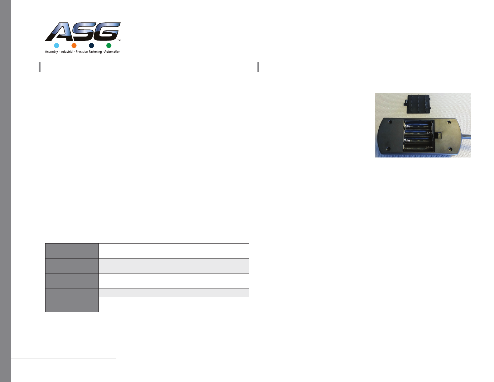
Installing the Batteries.....................................................................................2
Transducer Guidelines ......................................................................................2
Interchanging a Transducer ..............................................................................3
Safety Instructions............................................................................................3
Basic Operation................................................................................................3
Modes of Operation..................................................................................................4
Language Mode ...............................................................................................4
Units Mode ......................................................................................................4
Date Mode .......................................................................................................4
Track Mode ......................................................................................................5
Peak Mode .......................................................................................................5
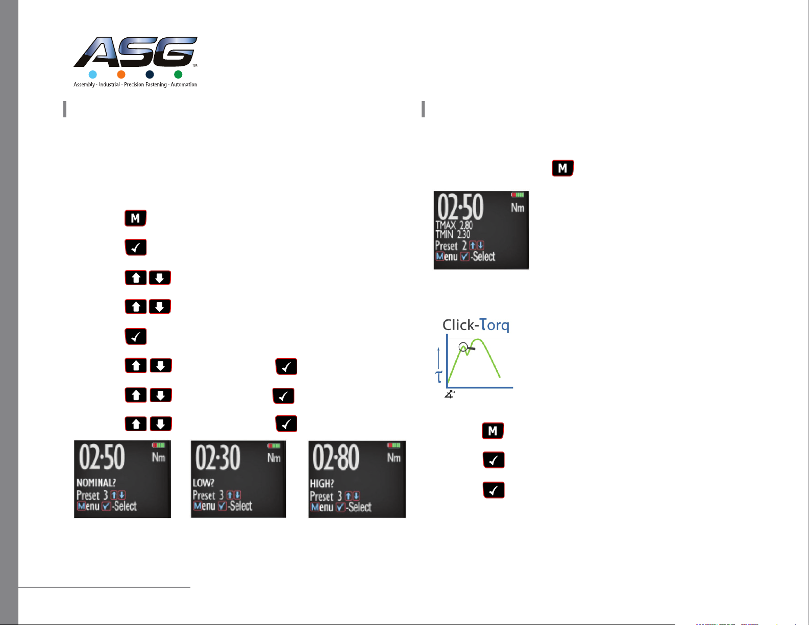
Preset Mode.....................................................................................................5
Set Mode..........................................................................................................6
Click-Torque Mode ...........................................................................................6
Dynamic Peak Mode ........................................................................................7
Recall Mode .....................................................................................................7
Upload Mode ...................................................................................................7
Comms Mode...................................................................................................7
Clear Mode ......................................................................................................8
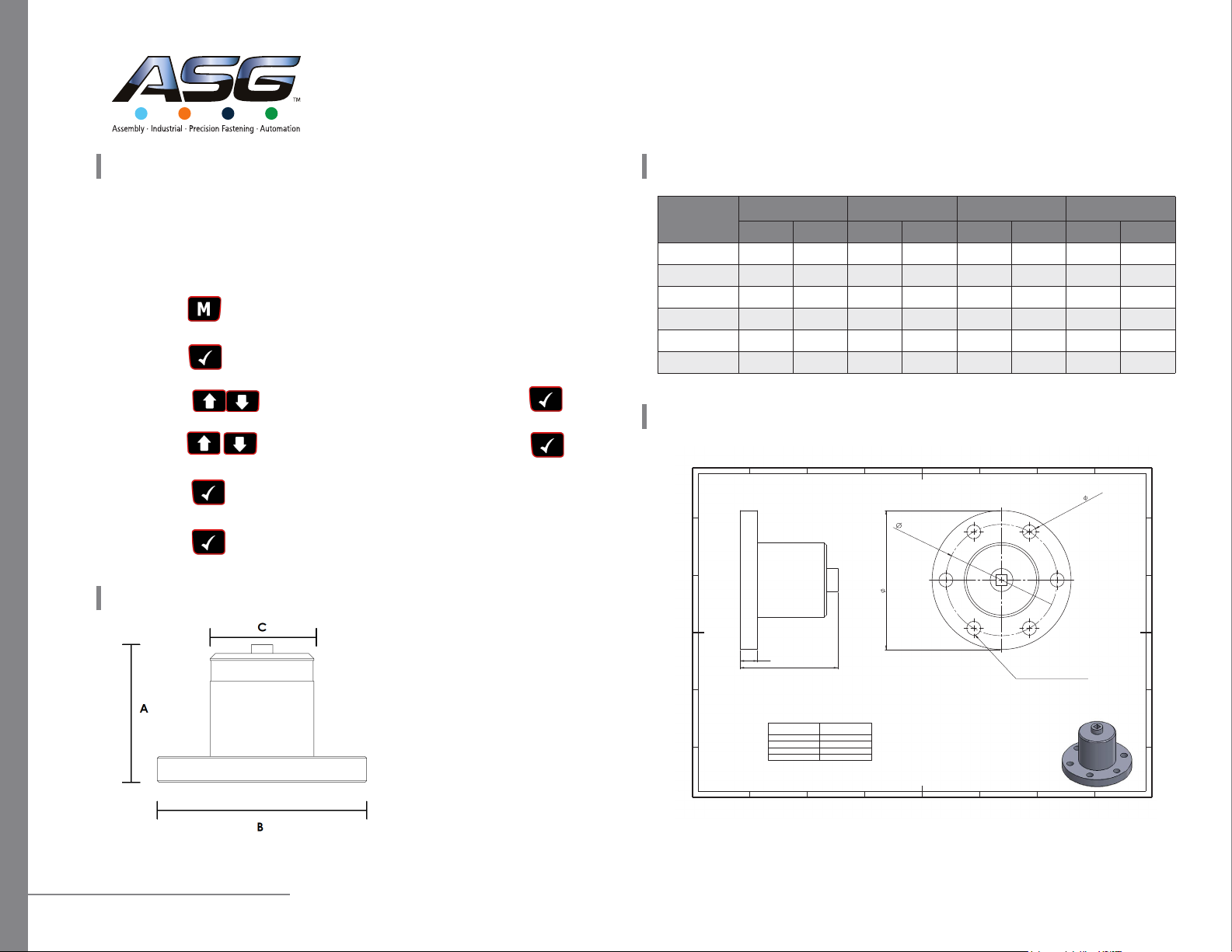
Product Dimensions .................................................................................................8
Transducer Flange .....................................................................................................8
Table of Contents Table of Contents (Cont.)
PCFE - PC Software...................................................................................................9
Installing the PCFE ...........................................................................................9
Communication with PCFE...............................................................................9
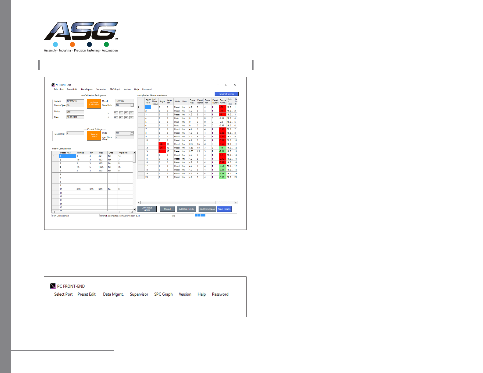
PCFE User Instructions ...........................................................................................10
Password........................................................................................................10
Menu Bar .......................................................................................................10
Calibration Settings........................................................................................11
Current Settings .............................................................................................11
Preset Conguration ......................................................................................11
Status Bar ......................................................................................................12
Results Table Controls ....................................................................................12
Results Table ..................................................................................................12
SPC Graph......................................................................................................13
Congure Torque Device Presets Using PCFE .................................................14
Add Data Field ...............................................................................................14
Wireless Communications ......................................................................................15
Connecting to a Wireless Receiver .................................................................15
Receiving Torque Results to the PCFE.............................................................15

ASG, Division of Jergens, Inc.
15700 S. Waterloo Road | Cleveland, OH 44110-3898 | Phone: (888) 486-6163 | Fax: (216) 481-4519 | Email: asginfo@asg-jergens.com | Web: www.asg-jergens.com | Revision: 07/21/2020 | Page 2 of 15
ASG ST Series Smart Transducer Digital Torque Tester
Operation Manual
The ASG ST Series Digital TorqueTester is a state of the art device suitable for torque testing
and torque calibration. As a precision tool, it is highly accurate and highly repeatable.
For product portfolio cohesion, the control module uses the same organic LED display,
membrane keypad, user interface and PC based data management software as other
standard products within this range of electronic torque tools. Additionally, training time is
kept to a minimum due to the ease of use of the tool itself.
Our products are demonstrated to have an accuracy of ±0.5% or better, and are both
simple to set and calibrate as well as coming with a fully traceable ISO 6789 certication.
The ASG ST Series Digital Torque Tester has both visual and audible alarms that signal good
or bad torque. Furthermore, there is a visual battery life indicator, alarms for preset value
approach, fastener overload, range overload, and maximum mechanical overload.
Recommended Use
The ASG Digital Torque Tester is specically designed for use in all industrial settings and
applications where high accuracy and repeatability combined with a complete torque data
management and control system are required. This tool is ideal for the regular accuracy
checking required for a torque wrench, and will ensure that on-site tools are compliant and
accurate to the relevant standards.
General Characteristics
Accuracy Right hand side torque = ±0.5% of actual reading
Left hand side torque = ±0.5% of actual reading
Resolution 0.01 to 50 N.m
0.1 to 1000 N.m
Alarms Preset Value Approach, Range Overload,
Mechanical Overload, Low Battery, Memory Full
Memory Capacity 2094 Values
Battery Life Sleep Mode: 5000 hours;
Operational Mode: Up to 120 hours (Up to 40 hours for wireless models)
Installing the Batteries
1. Remove the battery door.
2. Install 4 standard AA or 4 rechargeable
AA batteries in the required orientation.
3. Replace battery door.
4. Turn on the tester and check that the
device powers up.
Note: Standard and rechargeable batteries are
both suitable for use. Rechargeable batteries
should be charged ofine with suitable charger.
Transducer Guidelines
• Store in a dry location
• Do not exceed specied torques
• Do not use external forces on (i.e. a hammer)
• Apply torque perpendicularly to transducer
• Max torque for sockets:
• 1/4” = 30 N.m;
• 3/8” = 135 N.m,
• 1/2” = 400 N.m;
• 3/4” = 1000 N.m;
• 1” = 2000 N.m;
Basic Description and Guidelines Basic Description and Guidelines (Cont.)

ASG, Division of Jergens, Inc.
15700 S. Waterloo Road | Cleveland, OH 44110-3898 | Phone: (888) 486-6163 | Fax: (216) 481-4519 | Email: asginfo@asg-jergens.com | Web: www.asg-jergens.com | Revision: 07/21/2020 | Page 3 of 15
ASG ST Series Smart Transducer Digital Torque Tester
Operation Manual
Interchanging a Transducer
It is possible to interchange transducers with different torque ranges using the same
Smart Control Box (SCB – ASG Number 65200).
Instructions:
• Ensure the SCB power is off
• Unscrew the cable from the connector on the smart transducer
• Screw the cable into the same connector on the desired smart transducer
• Power on the SCB
• Ensure that no error messages appear; the device is now ready to operate
Safety Instructions
The following are a set of general guidelines for using and storing the tester that
should be adhered to at all times.
• All torque tools are precision instruments and should be handled with care
• Do not subject the tool to torque loads in excess of the model range
• Using non-linear extensions may affect the accuracy of the readings
• The use of torque extensions will increase the torque applied
• Do not operate the tool unless it has been powered on and the display screen can
be read clearly
• Do not drop the tool or subject it to heavy impact blows
• Ensure the tool is stored in a cool, dry location to protect from damage
Basic Operation
1. Product label
2. Colored LED warning indicators
3. Use “M” to scroll through the menu or return to the previous screen
4. Use the directional arrows to adjust values such as unites, torque settings, time, etc.
5. Use √ to enter mode, conrm setting or to save result to memory
Basic Description and Guidelines (Cont.) Basic Description and Guidelines (Cont.)

ASG, Division of Jergens, Inc.
15700 S. Waterloo Road | Cleveland, OH 44110-3898 | Phone: (888) 486-6163 | Fax: (216) 481-4519 | Email: asginfo@asg-jergens.com | Web: www.asg-jergens.com | Revision: 07/21/2020 | Page 4 of 15
ASG ST Series Smart Transducer Digital Torque Tester
Operation Manual
Torque reading starts at 5% of maximum capacity with an accuracy of 1% beginning at
10% of maximum capacity (threshold to maximum span).
The following are the different modes available with the ASG Digital Torque Tester:
• Language Mode
• Units Mode
• Date Mode
• Track Mode
• Peak Mode
• Preset Mode
• Set Mode
• Click-Torque Mode
• Dynamic Peak Mode
• Recall Mode
• Upload Mode
• Comms Mode
• Clear Mode
Language Mode
The languages of operation available to the user are: English,
Chinese, French, German, Italian, Polish, Portuguese, Russian,
Spanish.
Step 1: Press to scroll to the Language Menu
Step 2: Press to enter Language Menu.
Step 3: Press to scroll to the desired language.
Step 4: Press to conrm operation in this language.
Units Mode
The following units of measurement are available: kgf.cm,
kgf.m, cN.m, N.m, ozf.in, lbf.in, lbf.ft
Step 1: Press to scroll to the Units Menu.
Step 2: Press to enter Units Menu.
Step 3: Press to scroll to the desired units.
Step 4: Press to conrm selected units.
Date Mode
Step 1: Press to scroll to the Date Menu.
Step 2: Press to enter Date Menu.
Step 3: Press to scroll to set the minute and hour.
Step 4: Press to conrm.
Step 5: Repeat steps 3 and 4 to set the month, date and year.
Modes of Operation (Cont.) Modes of Operation (Cont.)

ASG, Division of Jergens, Inc.
15700 S. Waterloo Road | Cleveland, OH 44110-3898 | Phone: (888) 486-6163 | Fax: (216) 481-4519 | Email: asginfo@asg-jergens.com | Web: www.asg-jergens.com | Revision: 07/21/2020 | Page 5 of 15
ASG ST Series Smart Transducer Digital Torque Tester
Operation Manual
Track Mode
As torque is applied, the OLED will actively display the applied
torque reading from 5-100% of the maximum span of the device.
Upon removal of the load, the display will return to zero.
Step 1: Press to scroll to Track Mode.
Step 2: Press to operate in Track Mode.
Peak Mode
In Peak mode, the maximum torque reading will remain on the
OLED display when the load is removed as long as the torque
loaded is above the 10% of maximum capacity threshold. The
user has the option to store the reading in memory. If storage
of the reading is not required, the user may continue to the next
measuring task.
Step 1: Press to scroll to Peak Mode.
Step 2: Press to operate in Peak Mode.
Step 3: Press to store the peak value if required.
Preset Mode
In Preset mode, the maximum torque reading will remain on
the OLED display when the load is removed as long as the
torque loaded is above the 10% of maximum capacity
threshold. Depending on the maximum torque recorded, there
are various warning signals activated:
• Passing Minimum Value: the green LED on the keypad
will ash and the buzzer will sound intermittently. The OLED
display will change to orange.
• Passing Nominal Value: the green LED on the keypad will turn on and the buzzer
will sound continuously. The OLED display will change to green.
• Passing Maximum Value: The red LED will ash continuously and the buzzer will
sound continuously. The OLED will change to red.
Step 1: Press to scroll to Preset Mode.
Step 2: Press to enter Preset Mode.
Step 3: Press to select your preferred preset number (1 to 99).
Step 4: Press to operate within this preset parameter.
Step 5: Press to store the applied torque if required.
Modes of Operation (Cont.) Modes of Operation (Cont.)

ASG, Division of Jergens, Inc.
15700 S. Waterloo Road | Cleveland, OH 44110-3898 | Phone: (888) 486-6163 | Fax: (216) 481-4519 | Email: asginfo@asg-jergens.com | Web: www.asg-jergens.com | Revision: 07/21/2020 | Page 6 of 15
ASG ST Series Smart Transducer Digital Torque Tester
Operation Manual
Set Mode
This mode allows the user to set limits for the torque applied or measured. The operator
can choose to set torque values by percentage or numerical tolerance. During operation
the OLED display will be green when approaching the preset tolerance and will change to
red if exceeded.
Step 1: Press to scroll to Set Mode.
Step 2: Press to select Set Mode.
Step 3: Press to scroll to set by percentage or set by tolerance.
Step 4: Press to scroll to required preset number (i.e. 1 to 99).
Step 5: Press to conrm preset number selected.
Step 6: Press to set nominal value and to conrm.
Step 7: Press to set your low value and to conrm.
Step 8: Press to set your high value and to conrm.
Set Mode (Cont.)
Step 9: Once the parameters have been conrmed the operator can nd the congured
preset within Preset Mode. Use to select Preset Mode from the main menu and nd
the desired preset number.
Click-Torque Mode
In Click-Torque mode, the rst peak reading will remain on the
OLED display when the load is removed as long as the torque
loaded is above the 10% of maximum capacity threshold. This
mode is best suited to capturing the click-out point of a mechanical
click wrench which can then be compared to the etched, printed
dial scale on the tool itself. Once captured, the user has the option
to store the reading to memory. If storage of the reading is not
required, the user may continue to the next measuring task.
Step 1: Press to scroll to Click-Torque Mode
Step 2: Press to operate in Click-Torque Mode
Step 3: Press to store the rst peak value recorded if desired
Modes of Operation (Cont.) Modes of Operation (Cont.)

ASG, Division of Jergens, Inc.
15700 S. Waterloo Road | Cleveland, OH 44110-3898 | Phone: (888) 486-6163 | Fax: (216) 481-4519 | Email: asginfo@asg-jergens.com | Web: www.asg-jergens.com | Revision: 07/21/2020 | Page 7 of 15
ASG ST Series Smart Transducer Digital Torque Tester
Operation Manual
Dynamic Peak Mode
In Dynamic Peak mode, the nal peak value will remain on the
OLED display when the load is removed as long as the torque
loaded is above the 10% of maximum capacity threshold. The
mode is best suited to capturing the nal installed torque (2nd
peak) for click wrenches, the peak torque of slipping wrenches/
screwdrivers, or in conjunction with a joint simulator, the peak
torque of suitable rotary tools of 1200 RPM or less. Please note
that impact of erratic drive pulse tools are not suitable for testing with the ASG range of
digital torque testers. Once captured,the user has the option to store the reading to memory.
If storage of the reading is not required, the user may continue to the next task.
Step 1: Press to scroll to the Dynamic Peak mode.
Step 2: Press to operate in Dynamic Peak mode.
Step 3: Press to scroll to the required preset number (i.e. 1 to 99).
Step 4: Press to select the desired preset.
Step 5: Press store the maximum peak value if desired.
Recall Mode
This mode allows the user to view the stored torque data. Only locations containing data
will be displayed. Note that as data is stored, the locations are populated sequentially from
01 to 2094.
Step 1: Press to scroll to Recall Mode.
Step 2: Press to enter and view memory locations, results, and functions.
Step 3: Press to scroll through locations that contain data.
Modes of Operation (Cont.)
Upload Mode
This mode allows the user to upload stored torque data. In Upload Mode, the device must
be connected to a PC running the PC Front-End Software (PCFE) via the USB port on the
Receiver and the PC.
Step 1: Press to scroll to Upload Mode.
Step 2: Press to enter Upload Mode.
Step 3: Press to select “From” and for the starting point of the
results upload.
Step 4: Press to conrm “From” location.
Step 5: Press to select “To” and for the nishing point of the results upload.
Step 6: Press to conrm, press against when you are asked are you sure.
Comms Mode
This mode allows the user to select the method of communication. The standard model
allows communication by standard USB cable to the included software. For communication
by ASCII or BINARY, the SCB/WCBR will need physical modications in advance.
Step 1: Press to scroll to Comms Mode.
Step 2: Press to enter Comms Mode.
Step 3: Press to select the method of communication and to conrm.
Note: For standard communication to the included software program, select ‘PCFE’
Modes of Operation (Cont.)

ASG, Division of Jergens, Inc.
15700 S. Waterloo Road | Cleveland, OH 44110-3898 | Phone: (888) 486-6163 | Fax: (216) 481-4519 | Email: asginfo@asg-jergens.com | Web: www.asg-jergens.com | Revision: 07/21/2020 | Page 8 of 15
ASG ST Series Smart Transducer Digital Torque Tester
Operation Manual
Transducer Flange
Product Dimensions
97
Tester Torque
Range Overall Height 'A'
0.05 - 20 Nm 81 mm
5 - 135 Nm 119 mm
15 - 340 Nm 119 mm
50 - 500 Nm 133 mm
E
C
87
A
B
23456 1
578 246 13
E
D
C
F F
D
B
A
UNLESS OTHERWISE SPECIFIED:
DIMENSIONS ARE IN MILLIMETERS
HOLES SIZED FOR M12 BOLTS
6x12.10
121
15
A
Tester Range A B C Weight
mm in. mm in. mm in. kg lb
0.05-20 N.m 75 3 Ø 121 Ø 4.8 Ø 70 Ø 2.76 0.72 1.6
5-135 N.m 120 4.7 Ø 121 Ø 4.8 Ø 70 Ø 2.76 0.94 2.1
15-340 N.m 120 4.7 Ø 121 Ø 4.8 Ø 70 Ø 2.76 1.2 2.6
50-750 N.m 135 5.3 Ø 121 Ø 4.8 Ø 70 Ø 2.76 1.6 3.5
100-1000 N.m 147 5.8 Ø 121 Ø 4.8 Ø 70 Ø 2.76 2.8 6.2
150-2000 N.m 177 7 Ø 121 Ø 4.8 Ø 70 Ø 2.76 3.8 8.4
Clear Mode
This mode allows the user to clear the stored data from a range of locations. Before clearing
the selected range and as a safety precaution,the user will be asked are they sure they wish
to clear selected data. This can be done by pressing the conrm button.
Step 1: Press to scroll to Clear Mode.
Step 2: Press to enter Clear Mode.
Step 3: Press to select “From” range to be cleared and press to conrm.
Step 4: Press to conrm “To” range to be cleared and press to conrm.
Step 5: Press to conrm and you will be asked if you are sure.
Step 6: Press to conrm and that the range of the data is cleared from memory.
Modes of Operation (Cont.) Product Dimensions (Cont.)

ASG, Division of Jergens, Inc.
15700 S. Waterloo Road | Cleveland, OH 44110-3898 | Phone: (888) 486-6163 | Fax: (216) 481-4519 | Email: asginfo@asg-jergens.com | Web: www.asg-jergens.com | Revision: 07/21/2020 | Page 9 of 15
ASG ST Series Smart Transducer Digital Torque Tester
Operation Manual
Installing the PCFE
PCFE - “PC Front End” is the standard software that the device communicates with and
is included with the tool.
1. Download the software from the ASG product page on asg-express.com. Select
“setup.exe”
2. Choose one of the following options based on your requirements;
• Demo PCFE: This will allow the user to test the software without installing it
on a PC or laptop.
• Install PCFE.exe: install the software to the PC or laptop for full functionality.
• Instructions - User Manual
3. Install the PCFE.exe
• During the steps for installation, there is a search to ensure the .net framework
is present and installs it from the web if required.
• USB drivers are automatically installed. If there are any issues achieving this
they can also be manually installed from: C:/program les/PCFE/Front-End/USB
Drivers.
• Subsequent to installation, the PCFE icon will appear on the desktop. Double
click the icon and contact ASG for the password.
• At this stage the PCFE window can be resized. Once altered, it will stay as such
until modied again.
PCFE - PC SOFTWARE
Communication with PCFE
1. Connect a USB Cable from PC to the torque device. The HID driver will self-install
and prompt you when the process is complete (See Figure 1).
2. When in the “Select Port” menu from the top left of the PCFE, there will be two
options:
• Com Port 1: Select this option if you require and have the capability of serial
communication.
• Torque Device: This will allow you to connect your torque device via USB.
Figure 1: Desktop Notication for Driver Installation
PCFE - PC Software

ASG, Division of Jergens, Inc.
15700 S. Waterloo Road | Cleveland, OH 44110-3898 | Phone: (888) 486-6163 | Fax: (216) 481-4519 | Email: asginfo@asg-jergens.com | Web: www.asg-jergens.com | Revision: 07/21/2020 | Page 10 of 15
ASG ST Series Smart Transducer Digital Torque Tester
Operation Manual
PCFE User InstructionsPCFE User Instructions
Password
A prompt will appear asking for a password - no password is needed. Please leave blank
and click enter.
Menu Bar
Figure 3: Main PCFE Screen
Figure 5: PCFE Menu Bar
Menu Bar (Cont.)
1. Select Port: Allows the user to connect with the torque device (See Figure 2)
2. Preset Edit: A preset is a set of torque/torque and angle parameters
• Clear all: Delete existing presets from the table, use “Store to Device” to save
this update to device .
• Load from File: Load presets from a .csv le to the torque device.
• Save to File: Export the preset table to a .csv le.
3. Data Mgmt:
• Save Results: Save measurement results to a .csv le
• Print Results: Print measurement results.
• Clear Results: Delete all the results from the table.
• Page Setup: Set print layout for the “Print Results” option.
4. Supervisor:
• Clear Product Results: Permanently delete all measurement results from the
torque device.
• Enable/Disable: Hides all torque device modes except for “Preset”. On the next
startup, all modes except preset will be enabled/disabled.
• Torque Counter: Can only be enabled/disabled on compatible products and the
counter limits set.
• Reset Product: Perform factory reset on the Torque Device. Note: This deletes all
information on the torque device including calibration information.
5. SPC Graph: Creates a visual representation of the chosen torque results. Note: This
feature is only available when ten or more measurements using the same preset
have been uploaded to the PCFE
6. Version: Shows current version of the PCFE
7. Help: Leads to instruction manuals for PCFE operation

ASG, Division of Jergens, Inc.
15700 S. Waterloo Road | Cleveland, OH 44110-3898 | Phone: (888) 486-6163 | Fax: (216) 481-4519 | Email: asginfo@asg-jergens.com | Web: www.asg-jergens.com | Revision: 07/21/2020 | Page 11 of 15
ASG ST Series Smart Transducer Digital Torque Tester
Operation Manual
PCFE User InstructionsPCFE User Instructions
Calibration Settings
1. Serial #: The serial number of the product which can be linked to a calibration certicate.
2. Model: The model number is the default value used but can be changed it required
without effecting the calibration of the torque device.
3. Device Span: The upper torque limit of the torque device is shown here.
4. Span Units: This displays what units the torque device was calibrated in.
5. Period: The number of days from the date of calibration until it is recommended that
the torque device is recalibrated.
6. Date: The date on which the torque device was last calibrated.
Current Settings
Figure 6: Calibration Settings Screen
Figure 7: Current Settings
Current Settings (Cont.)
1. Sleep: The time in minutes before the torque device will enter sleep mode if left idle.
If the operator applies torque or uses the torque device control buttons the sleep
counter is reset.The torque device will not enter sleep while connected via USB to PC.
2. Units: Current units of measurement (Nm is the default setting).
3. Just Move (Deg)°: The default Just Move angle setting, which is the angle at which a
snapshot of the torque is taken during the Just Move mode application.
Preset Conguration
The Preset Conguration Screen shows the presets that are stored on the torque device.
Presets can be congured either in the PCFE or on the torque device.
For instructions on how to add a preset using the PCFE, please see the section “Set a Preset
using the PCFE”.
Figure 8: Preset Conguration Screen

ASG, Division of Jergens, Inc.
15700 S. Waterloo Road | Cleveland, OH 44110-3898 | Phone: (888) 486-6163 | Fax: (216) 481-4519 | Email: asginfo@asg-jergens.com | Web: www.asg-jergens.com | Revision: 07/21/2020 | Page 12 of 15
ASG ST Series Smart Transducer Digital Torque Tester
Operation Manual
PCFE User InstructionsPCFE User Instructions
Status Bar
1. Port status: Displays which port is being used by the torque device.
2. Connection Status: Displays the current status of the PCFE’s connection to a torque
device.
3. Software version: The current rmware version on the torque device.
4. PCFE Status: Displays what actions are currently being processed by the PCFE.
5. Progress Bar: A visual progress bar, defaults to three bards when connected.
Results Table Controls
1. Continuous Upload: If this option is selected and the torque device is permanently
connected to the PCFE via USB or RS232 cables, the results of the torque device will
continuously upload to the PCFE as the measurements are taken with the torque
device.
2. Upload All: Once the torque device is connected to the PCFE, selecting this option will
upload all the measurements stored on the torque device.
3. Set Data Fields: This is used to add columns to the PCFE results section.These columns
contain comments that are applied to all subsequent results.
4. Unit Conversion: Converts the units of the existing results in the table to Nm, cNm,
kgm, kgfcm, lbft, lbin or ozin.
5. Save Results: Save results to a .csv le.
6. Power off Device: Turn off and disconnect the torque device from the PCFE.
Results Table
The results table is only populated when torque results are uploaded to the PCFE. Results
that are highlighted in green indicate that the torque or torque or angle measurement
was “good”, i.e. the torque or angle applied was within the pre-congured tolerances.
Conversely, results highlighted in red indicate that the torque or angle measurement was
“bad”, i.e. the torque or angle applied fell outside the pre-congured tolerances.
Figure 9: Status Bar
Figure 9: Results Table

ASG, Division of Jergens, Inc.
15700 S. Waterloo Road | Cleveland, OH 44110-3898 | Phone: (888) 486-6163 | Fax: (216) 481-4519 | Email: asginfo@asg-jergens.com | Web: www.asg-jergens.com | Revision: 07/21/2020 | Page 13 of 15
ASG ST Series Smart Transducer Digital Torque Tester
Operation Manual
PCFE User InstructionsPCFE User Instructions
SPC Graph
To access SPC graphic functionality there must be at least ten results uploaded to the PCFE.
Figure 10 shoes the control panel of the SPC Graph feature.
1. Date Range: This setting is used to select the range of results that are to be graphed.
The minimum and maximum values default to the oldest and latest results respectively.
To change these dates, press the button above the appropriate date. These select the
desired date from the calendar.
2. Preset Select: Select the preset you wish to graph. Note: To graph a preset, at least
10 measurements for the individual preset must be reset.
3. Maximum Number of Readings: This sets the maximum number of results to be
graphed for a given preset and date range. If there are 50 results for that particular
parameter and 10 readings are selected, the earliest results will be graphed.
4. Print Graph: Print the current graph.
5. Graph: Creates the graph as per the parameters entered in the data elds.
Note: To produce a line graph the results table must be ordered by the “PCFE #” column. If
not, the time axis of the graph will be affected and a standard scatter chart will be shown.
Upon graphing a set of results (Figure 12), the Cpk and standard deviation are automatically
calculated, and displayed in the bottom right of the screen (Figure 11).
SPC Graph (Cont.)
Figure 11: Cpk and Standard Deviation Values
Figure 12: SPC Graph Output of a Torque Only Pre-Set

ASG, Division of Jergens, Inc.
15700 S. Waterloo Road | Cleveland, OH 44110-3898 | Phone: (888) 486-6163 | Fax: (216) 481-4519 | Email: asginfo@asg-jergens.com | Web: www.asg-jergens.com | Revision: 07/21/2020 | Page 14 of 15
ASG ST Series Smart Transducer Digital Torque Tester
Operation Manual
PCFE User InstructionsPCFE User Instructions
Congure Torque Device Presets Using PCFE
1. Ensure the torque device is connected to the PCFE software selected using “Select
Port” (Figure 13).
2. Select the preset number or location from 1 to 99 you wish to set.
3. When the pop up window appears, ll in required elds and press “O.K.”
4. Select ‘Store to Torque Device’. The data is then written to the Torque Device
NOTE: Some series of torque device only have the capability for one preset to be congured.
Torque or torque and angle parameters can be set product dependent.
Add a Data Field
1. Select the “Add Data Fields” button on the bottom right of the main PCFE window.
2. Enter column title and select either “Auto-Fill” or “Manual Entry” button. If “Auto-
Fill” button is selected then the value entered in “Cell Entry” will be set as default.
3. Hit the save button and the column will be added to the results table on the far
right.
NOTE: If enable column is not selected, the column will not appear at all in the PCFE.
Figure 13: Setting Presets via the PCFE
Figure 14: Adding a Default Data Field

ASG, Division of Jergens, Inc.
15700 S. Waterloo Road | Cleveland, OH 44110-3898 | Phone: (888) 486-6163 | Fax: (216) 481-4519 | Email: asginfo@asg-jergens.com | Web: www.asg-jergens.com | Revision: 07/21/2020 | Page 15 of 15
ASG ST Series Smart Transducer Digital Torque Tester
Operation Manual
Wireless Communications (Cont.)Wireless Communications
Connecting to a Wireless Receiver
1. Connect a USB Cable from the PC to the WCBR (Wireless receiver). The HID driver will
self-install and prompt you when the process is complete (See Figure 15).
2. After clicking the ‘Select Port’ tab from the top left of the PCFE, select the following
option:
RF Master – This will allow you to connect your torque device via USB.
Receiving Torque Results to the PCFE
1. After connection to the WCBR the PCFE screen will automatically change to a wireless
data screen as per the sample screenshot below.
2. On the upper left of the screen the wireless symbol highlights to indicate an incoming
torque result. On the lower left side of the screen the most recent result and when it
was received is displayed.
3. Torque results will be received from all TW wrenches which are within range of the
WCBR (circa 10-15 meters).
4. All results can be sorted by date or torque device serial number within the torque
results table to the right of the screen.
5. Sub-section “Controls for Results Table” above advises the controls possible with the
results table.
Figure 16: Selecting suitable COM port
Figure 17: Wireless RF page
Figure 15: Desktop Notication for Driver Installation
This manual suits for next models
1
Table of contents
Popular Test Equipment manuals by other brands

Time Electronics
Time Electronics 5068 Ins-Cal user manual

Keysight
Keysight 85056A User's and service guide

Tektronix
Tektronix 2232 Service manual

Gossen MetraWatt
Gossen MetraWatt METRAVOLT 12D+L operating instructions

SCHUNK
SCHUNK GFT-X 270 operating manual

Powerfix Profi
Powerfix Profi PAWSB 12 A1 operating instructions