Asyril Asycube User manual

Asycube
Operating Manual
Document
Asyril_ACUBE-XXX-
02_Operating_Manual_E_temp
Version
v1.7
Date
26.07.2012
Articles
ACUBE-MEZ-02--XX-XX-XX-XX
ACUBE-FOR-02--XX-XX-XX-XX


Asycube - Asyril SA
Operating Manual
© Copyright Asyril S.A.
Introduction
v1.7
FO 32.03.118
Operating Manual Asycube -Asyril SA 3/41
Table of Contents
1. INTRODUCTION...............................................................................................................................5
GENERALITIES..........................................................................................................................51.1.
SAFETY PRECAUTIONS.............................................................................................................61.2.
General safety precaution...................................................................................................61.2.1.
Specific warnings..................................................................................................................71.2.2.
WARRANTY INFORMATION........................................................................................................91.3.
CE INFORMATION .....................................................................................................................91.4.
RELATED MANUALS ..................................................................................................................91.5.
2. DESCRIPTION................................................................................................................................10
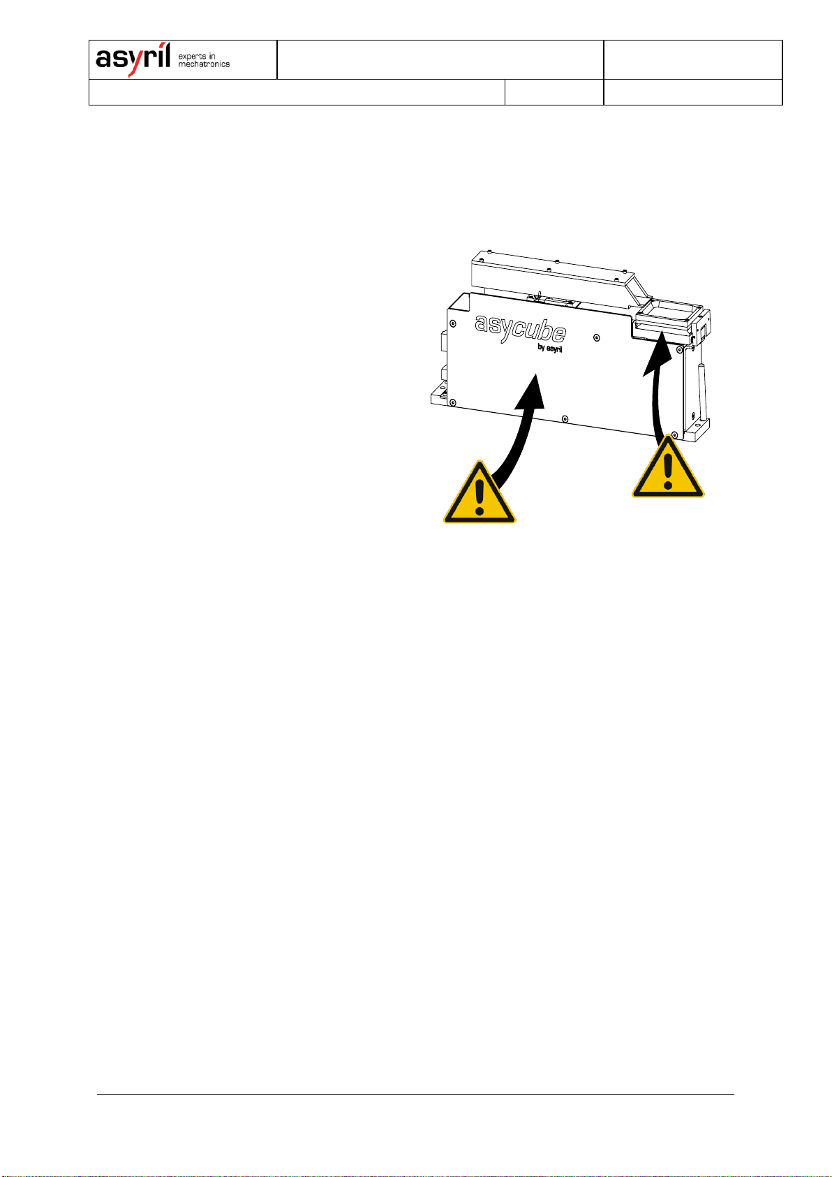
FIRST GLIMPSE AT THE PRODUCT...........................................................................................102.1.
Asycube 3D platform (A) ...................................................................................................102.1.1.
Asycube removable bulk (B).............................................................................................112.1.2.
GENERAL CHARACTERISTICS.................................................................................................122.2.
Technical features..............................................................................................................122.2.1.
Overall dimensions.............................................................................................................132.2.2.
Visual signals ......................................................................................................................152.2.3.
PERFORMANCE.......................................................................................................................162.3.
Workspace (Picking surface)............................................................................................162.3.1.
Displacement of the parts..................................................................................................162.3.2.
ELECTRIC INTERFACES ..........................................................................................................172.4.
Overview..............................................................................................................................172.4.1.
Asylink..................................................................................................................................182.4.2.
Node link..............................................................................................................................212.4.3.
Power connection...............................................................................................................212.4.4.
Backlight Synchronization.................................................................................................222.4.5.
COMMUNICATION INTERFACE.................................................................................................232.5.
Specifications......................................................................................................................232.5.1.
Baudrate ..............................................................................................................................232.5.2.
Serial Timing .......................................................................................................................242.5.3.
Asycube Serial Network ....................................................................................................262.5.4.
MECHANICAL INTERFACES .....................................................................................................272.6.
Attachment of the Asycube...............................................................................................272.6.1.
ACCESSORIES AND OPTIONAL MODULES...............................................................................282.7.
Additional platform..............................................................................................................282.7.1.
Additional container............................................................................................................282.7.2.
Customized platforms........................................................................................................292.7.3.
Color of the backlight .........................................................................................................292.7.4.

Asycube - Asyril SA
Operating Manual
© Copyright Asyril S.A.
Introduction
v1.7
FO 32.03.118
Operating Manual Asycube -Asyril SA 4/41
3. TRANSPORTATION, HANDLING AND INSTALLATION.......................................................30
PACKAGING OF THE PRODUCT,TRANSPORTATION AND HANDLING .......................................303.1.
BEFORE UNPACKING...............................................................................................................303.2.
UNPACKING INSTRUCTIONS....................................................................................................313.3.
INSTALLATION AND STORAGE ENVIRONMENT.........................................................................333.4.
Installation environment.....................................................................................................333.4.1.
Storage environment..........................................................................................................333.4.2.
4. MAINTENANCE AND REPARATION.........................................................................................34
SAFETY PRECAUTIONS...........................................................................................................344.1.
General safety precautions...............................................................................................344.1.1.
Specific warnings................................................................................................................344.1.2.
PERSONNEL RESPONSIBLE FOR MAINTENANCE OR REPARATION..........................................344.2.
MAINTENANCE........................................................................................................................354.3.
Periodic maintenance schedule .......................................................................................354.3.1.
Remove the platform module............................................................................................364.3.2.
Exchange of the backlight.................................................................................................364.3.3.
Cleaning bulk.......................................................................................................................374.3.4.
Control and Cleaning of the platform...............................................................................374.3.5.
Cleaning 3D vibration module...........................................................................................374.3.6.
Voicecoils control and audit of component behavior.....................................................374.3.7.
REPARATION...........................................................................................................................384.4.
TECHNICAL SUPPORT.............................................................................................................394.5.
For better service …...........................................................................................................394.5.1.
Contact.................................................................................................................................394.5.2.

Asycube - Asyril SA
Operating Manual
© Copyright Asyril S.A.
Introduction
v1.7
FO 32.03.118
Operating Manual Asycube -Asyril SA 5/41
1. Introduction
Generalities1.1.
The following document is the property of Asyril S.A. and may not be copied or circulated
without permission. The information contained in this document is subject to change without
notice for the purpose of product improvement. Before operating your product, please read
this document in order to ensure a correct use of the product. Nevertheless, if you meet
difficulties during the operation or the maintenance, please, feel free to contact Asyril
customer service.
In this manual, the safety precautions that you must respect are classified as: “Danger”,
“Warning” and “Note”; the following symbols are used :
DANGER!
Failure to observe the instruction may result in death or serious injury.
DANGER!
Failure to observe the instruction may result in electrocution or serious injury due to
electric shock
WARNING!
Failure to observe the instruction may result in injury or property damage.
NOTE :
The user should read carefully this information to ensure the correct use of the product,
although failure to do so would not result in injury.
REFER TO …
For more information on a specific subject, the reader should read other manual, or refer to
other paragraph.
WARNING!
Asyril shall not be liable whatsoever for any loss or damage arising from a failure to observe
the items specified in “Safety Precautions.” The customer is responsible to provide the
necessary instruction to the persons concerned.
NOTE :
All dimensions in this document are expressed in millimeters

Asycube - Asyril SA
Operating Manual
© Copyright Asyril S.A.
Introduction
v1.7
FO 32.03.118
Operating Manual Asycube -Asyril SA 6/41
Safety precautions1.2.
General safety precaution1.2.1.
Transport1.2.1.1.
DANGER !
Be aware of the weight and take care when transporting the system. For more
information, please refer to chapter 3 “Transportation, handling and installation”
General1.2.1.2.
DANGER !
Be sure that all power sources and other cables to the unit are disconnected before
working on the product.
DANGER !
Only qualified personnel (trained by Asyril and with professional experience) are
authorized to work on this device.
DANGER !
Do not unscrew the housing of the system controls. Serious injury or death could
result from electric shock. Only authorized personnel from Asyril SA are allowed to
access this part of the system for maintenance or for repair.
DANGER !
Do not plug or unplug cables of the system unless it is switched off.
DANGER !
Never modify the product. Unauthorized modification may cause the product to
malfunction, resulting in injury, electric shock, fire, etc.
DANGER !
Turn off the power to the product in the event of power failure. Failure to do so may
cause the product to suddenly start moving when the power is restored.
DANGER !
Do not use the product in a place where the main unit or controller may come in
contact with water or oil droplets.

Asycube - Asyril SA
Operating Manual
© Copyright Asyril S.A.
Introduction
v1.7
FO 32.03.118
Operating Manual Asycube -Asyril SA 7/41
Disposal1.2.1.3.
When the product becomes no longer usable or necessary, dispose of it properly as an
industrial waste.
WARNING!
Observe the valid legal regulation for appropriate disposal protecting environment.
Specific warnings1.2.2.
Safety Equipment for Operators1.2.2.1.
- For safety reasons operators must wear protective eyewear when using the backlight of the
Asycube without diffuser installed. (the backlight lighting LEDs is equivalent to a Class 1
compared with lasers)
For more information on visible or non visible radiation emitted by the backlight, please refer
to “1.2.2.3 Specific warnings concerning this product” on page 8.
NOTE :
It is the customer responsibility to install warning signs informing that anyone working around
the Asycube must wear safety equipment.
Intervention groups1.2.2.2.
The following table defines the roles affected to each professional involved on the machine at
any time during its life cycle.
Operator
Fitter
Engineer
Support
Carrier
agent
Dismantler
Construction
X
Transportation
X
Installation
X
X
Commissioning
X
Use
X
Setting & Programming
X
Operation
X
Cleaning
X
X
Maintenance
X
Decommissioning
Dismantling
X
Table 1-1: Intervention groups

Asycube - Asyril SA
Operating Manual
© Copyright Asyril S.A.
v1.7
FO 32.03.118
Operating Manual Asycube -Asyril SA 8/41
Specific warnings concerning this product1.2.2.3.
(A) Backlight
The Asycube has an integrated
Backlight that persists of LED’s (Light
Emitting Diodes). These LED’s emit
visible or non-visible radiation
depending on the color of the
Backlight. LED’s illumination can
create discomfort, cornea, retinal and
lens damage. Do not look directly into
the light source without any personal
protection (e.g. protective eyewear).
Customers are encouraged to
document their unique application and
instruct employees on procedures to
limit exposure to LED radiation. This
Backlight is not constructed to be
used permanently. Please switch off
the illumination after image
acquisition. (Auto-switch OFF after
30” of timeout)
(B) Service
There are no user serviceable parts
inside the Asycube unit. Contact a
supplier to effect a service. In cases
of non respectation, the product
guarentee will expire.
Figure 1-1 :Specific warnings
concerning the Asycube

Asycube - Asyril SA
Operating Manual
© Copyright Asyril S.A.
v1.7
FO 32.03.118
Operating Manual Asycube -Asyril SA 9/41
Warranty information1.3.
You will find all the Asyril warranty information (duration, scope of warranty …) on the general
conditions of sale.
CE information1.4.
The original CE certificate for your
product is supplied at the time of
product delivery. “Figure 0-1 :
Specimen of a CE certificate”
provides an example of what your CE
certificate should look like.
Figure 0-1 : Specimen of a CE certificate
Related manuals1.5.
As described in the Table 0-1, this manual is an integral part of the Asycube documentation
set. This manual covers the installation, a technical description, the maintenance, and the
reparation of your system. Information on the transport and safety precautions are also
included in this manual.
Manual Title
Manual reference
Description of the
content
Asycube
Operating
manual
ACUBE-XXX-02_Operating_Manual_E_V1.2
THIS MANUAL
Asycube HMI
manual
ACUBE-XXX-01_HMI_Manual_E_V1.0
Describes how to use
the HMI (simply move
the parts, configure a
new recipe …)
Asycube
Programming
guide
ACUBE-XXX-01_Programming_Guide_E_V1.0
Describes the way of
programming an
Asycube .
Table 0-1 : related manuals

Asycube - Asyril SA
Operating Manual
© Copyright Asyril S.A.
Description
v1.7
FO 32.03.118
Operating Manual Asycube -Asyril SA 10/41
2. Description
First glimpse at the product2.1.
Asycube sets new standards in miniature part feeding. Its 3D vibratory platform allows fast
and flexible presentation of miniature parts (0.2 mm to 5 mm) to a robot equipped with a
vision system. It consists in :
(A) A 3D platform with integrated
backlight
(B) A removable bulk where the
components are stored
(C) Electrical interfaces performed
across a RS232 or a RS485
connection.
For more information on electrical
interfaces to the Asycube, please
refer to “2.4. Electric Interfaces” on
page 17
Figure 2-1 : Asycube overview
(D) A specific tool allowing to remove the platform easily
For more information on how to remove or change the platform, please refer to ”4.3.2.
Remove the platform module”on page 36
Asycube 3D platform (A)2.1.1.
The core of Asycube is a platform that can vibrate in three orthogonal directions. By selecting
appropriate actuator, excitation signals high flexibility in displacing parts on the platform is
reached (forward, backward, sidewise) and flipping is made possible.
For more information on the procedure to control the platform vibrations, please refer to the
HMI manual
The platform has an integrated backlight that allows easy recognition of the parts from a
camera placed above
For more information on the backlight color and the procedure to exchange the backlight,
please refer to “4.3.3 Exchange of the backlight”on page 36
(B)
(A)
(D)
(C)

Asycube - Asyril SA
Operating Manual
© Copyright Asyril S.A.
Description
v1.7
FO 32.03.118
Operating Manual Asycube -Asyril SA 11/41
DANGER !
Do not look directly into the light source without any personal protection !
Different parts have different behaviors. To reduce the stabilization time of a part, a different
vibrating platform can be useful and optimize therewith the functioning of the Asycube and
your application. The Asycube has a mechanism to change quickly the surface of the
vibrating platform.
For more information on how to remove or change the platform, please refer to ”4.3.2.
Remove the platform module” on page 36
Asycube removable bulk (B)2.1.2.
The components delivered in bulk are stored in a dedicated container that can be removed
from the feeder. This container is placed on a linear vibratory axis to progressively feed the
parts onto the 3D platform.
For more information on the procedure to control the bulk vibrations, please refer to the HMI
manual
Emptying the platform is made easy by lowering the container position automatically and
vibrating the parts backwards (not available for Asycube Y.600.835.000 // Y.600.835.003).

Asycube - Asyril SA
Operating Manual
© Copyright Asyril S.A.
Description
v1.7
FO 32.03.118
Operating Manual Asycube -Asyril SA 12/41
General Characteristics2.2.
WARNING !
Do not use the product outside the specifications. In cases of non-respectation, the product
guarantee will expire.
Technical features2.2.1.
Asycube mezzo
Asycube forte
Typical part size
from 0.2 mm to 3 mm side
length
from 3 mm to 8 mm side length
Integrated high quality
LED backlight
Interchangeable
backlight color
(green, red, blue, amber, white) please refer to “2.7.4 Color of the
backlight”on page 29 for more information.
Independent
vibrations in three
orthogonal directions
Interchangeable
vibration surface
please refer to section “2.7.1 Additional platform”on page 28 for
more information.
Vibration frequency
configurable
up to 350 Hz
up to 350 Hz
Easily detachable
container (Bulk)
Container (Bulk) can
be used to store the
parts

Asycube - Asyril SA
Operating Manual
© Copyright Asyril S.A.
Description
v1.7
FO 32.03.118
Operating Manual Asycube -Asyril SA 13/41
Overall dimensions2.2.2.
Figure 2-2 : overall dimensions
Characteristic
Asycube Mezzo
Asycube Forte
Footprint
C
46 mm
61 mm
D
293 mm
320 mm
Size of vibration
platform
A
34 mm
52 mm
B
45 mm
67 mm
Weight
3.5 kg
3.9 kg
D
114
190
138
24
C
B
A

Asycube - Asyril SA
Operating Manual
© Copyright Asyril S.A.
Description
v1.7
FO 32.03.118
Operating Manual Asycube -Asyril SA 14/41
Additional space is needed around the Asycube to be able to remove the platform module
with the specific tool (delivered with your Asycube) :
Figure 2-3 : overall dimensions with "lever"
Refer to “4.3.2 Remove the platform module”on page 36 for more information on how to
remove the platform :
Figure 2-4 : remove the platform
138
11
16
160
-
Toutes reproductions du document sans accord préalable écrit de l'entreprise propriétaire, ne sont pas autorisées.
N°Dessin
ACUBE-FOR-02--01-01-01-02
Asycube
1:2
Ech.
M-005899
Dessiné
1/1
FeuilleN°Article
600 835 009
Format
A3
Désignation
Masse (kg)
A
B
C
D
E
F
1 2 3 4 5 6 7 8 9
A
B
C
D
E
F
1 2 3 4 5 6 7 8 9
Usinage
ISO 2768-mk
Tolérances générales
-
MatièreTraitement
-
-
Vérifié-
-
CH-1690
Villaz-St-Pierre
Rev.
-
3.885
160
11
16

Asycube - Asyril SA
Operating Manual
© Copyright Asyril S.A.
Description
v1.7
FO 32.03.118
Operating Manual Asycube -Asyril SA 15/41
Visual signals2.2.3.
The led give important information on
the state of the Asycube :
Led
State
Meaning
1
On
AsyProbe
incoming data
from the PC
2
On
AsyProbe sending
a response to PC
3
On
AsyLink incoming
data from the PC
4
On
AsyLink sending a
response to PC
Led
State
Meaning
1
Blinking
”ton”
100ms
System in
standby
Blinking
“ton”
900ms
System in service
2
Blinking
100ms
Alarm occurs
3
On
Motor On (only
with mechanism
up/down)
4
On
Power Supply
3.3V ready
5
On
Actuator X active
6
On
Actuator Y active
7
On
Actuator Z active
8
On
Actuator Bulk
active
Figure 2-5 : AsyProbe/AsyLink Indicator LED’s
Figure 2-6 : Asycube Operating Indicator LED’s
1
2
3
4
5
6
7
8
1
2
3
4

Asycube - Asyril SA
Operating Manual
© Copyright Asyril S.A.
Description
v1.7
FO 32.03.118
Operating Manual Asycube -Asyril SA 16/41
Performance2.3.
Workspace (Picking surface)2.3.1.
The picking surface dimensions
corresponds to the Asycube platform
size :
Data
Asycube
Mezzo
Asycube
Forte
A
34 mm
52 mm
B
45 mm
67 mm
Figure 2-7 : Picking surface
Displacement of the parts2.3.2.
To define a specific movement with
the Asycube several parameters need
to be extracted. For every movement
on the cube, twelve parameters must
be set. Calling these twelve
parameters will generate specific
vibrations (corresponding to the sum
of the movements of the three
actuators in the three dimensions X, Y
and Z).
The figure on the right shows the
predefined parameters and the
associated movements.
For more information on these
parameters, and to learn how to
configure them, in order to control the
cube and bulk vibrations, please refer
to the HMI manual
Figure 2-8 : predefined displacement of the parts

Asycube - Asyril SA
Operating Manual
© Copyright Asyril S.A.
Description
v1.7
FO 32.03.118
Operating Manual Asycube -Asyril SA 17/41
Electric Interfaces2.4.
Overview2.4.1.
Asycube is a standalone module with
its own control electronics. The
electrical interfaces to the Asycube
are situated at the back of the
product:
(A) Asyprobe
NOTE :
This connector is reserved for
diagnosis purpose only.
(B) Asylink
(C) Node link
(D) Power connection
(E) Backlight synchronization
NOTE :
Only connectors are part of the
delivery, the cables are not supplied.
All the interfaces are described in
detail in the following sections.
WARNING !
You must use shielded cables
grounded with the final machine to
avoid undesired disturbances.
Figure 2-9 : Electrical interfaces to the Asycube
(A)
(B)
(C)
(D)
(E)

Asycube - Asyril SA
Operating Manual
© Copyright Asyril S.A.
Description
v1.7
FO 32.03.118
Operating Manual Asycube -Asyril SA 18/41
Asylink2.4.2.
The Asycube units are either factory configured for RS-232 or RS-485 “AsyLink” protocol
operations. Depending on the configuration the connection have to be made differently. RS-
232 is used when only one Asycube system is integrated in the final machine whereas RS-
485 is used when an Asycube-Network has to be established.
For more information on the installation of an Asycube RS-485 network (default installation),
please refer to “2.5.4. Asycube Serial Network” on page 26.
Connecting RS-485 “AsyLink” 2.4.2.1.
When AsyCube is configured for RS-485 multidrop operation, the differential wire pair at each
end of the network must be terminated with a set of terminating resistors.
Figure 2.10: "AsyLink" RS485 connection scheme
NOTE : RS-485 wiring considerations
Do not cross positive and negative signals. Positive terminals must be wired to positive and
negative terminals to negative.
Termination resistors should be placed only at the extreme ends of the data line, and not
more than two terminations should be placed in any single segment of an RS-485 network
AsyCube RS485 Cable
XS 202 –Type HARTING MINI 3.81 4PF

Asycube - Asyril SA
Operating Manual
© Copyright Asyril S.A.
Description
v1.7
FO 32.03.118
Operating Manual Asycube -Asyril SA 19/41
XS202 (.)
Signal
Description
XS202 (1)
GND
This common signal is
a dedicated return to
internal system
ground. All serial
communications
should be referenced
to this pin. The
function of the signal
ground wire is to tie
the signal ground of
each of the node to
one common ground.
The second function of
the signal 0V is to pull
down the data(-) with
the termination
resistor.
XS202 (2)
DO-
/RI-
This digital signal is
used to transmit and
receive data(-)
according to RS-485
protocol.
XS202 (3)
DO+
/RI+
This digital signal is
used to transmit and
receive data(+)
according to RS-485
protocol.
XS202 (4)
VCC
This +5VDC signal is a
dedicated return to
internal system. The
function of the signal
+5V is to pull up the
data(+) with the
termination resistor.
Figure 2-11 : Asylink (RS 485) interface
XS202 (4)
XS202 (1)

Asycube - Asyril SA
Operating Manual
© Copyright Asyril S.A.
Description
v1.7
FO 32.03.118
Operating Manual Asycube -Asyril SA 20/41
Connecting RS-232 “AsyLink” 2.4.2.2.
NOTE :
When the Asycube is configured in RS-232 mode, the address node has to be set at value
“0”. Otherwise the Asycube will not work.
Figure 2.12: Asylink RS-232 scheme
XS202 (.)
Signal
Description
XS202 (1)
GND
This common signal is
a dedicated return to
internal system
ground. All serial
communication should
be referenced to this
pin.
XS202 (2)
RXD
This input signal is
used to receive data
according to RS-232
protocol
XS202 (3)
TXD
This output signal is
used to transmit data
according to RS-232
protocol.
XS202 (4)
VCC
This signal is not used
Figure 2-13 : Asylink (RS 232) interface
XS202 (4)
XS202 (1)
AsyCube RS232 Cable
XS 202 –Type HARTING MINI 3.81 4PF
Host Computer
RS232 sub-D 9poles
CTS - 8
RTS - 7
TXD - 3
RXD - 2
DSR - 6
DTR - 4
DCD - 1
GND - 5
TXD –XS202(3)
RXD –XS202(2)
GND –XS202(1)
Other manuals for Asycube
2
Table of contents
Other Asyril Industrial Equipment manuals

Asyril
Asyril Asycube Series User manual

Asyril
Asyril Asycube 240 User manual

Asyril
Asyril Asycube Series Instruction Manual

Asyril
Asyril Asycube Largo A5 User manual

Asyril
Asyril Asycube 50 User manual

Asyril
Asyril Asycube Control URCap User manual

Asyril
Asyril SmartSight Operating instructions

Asyril
Asyril Asycube 380 User manual

Asyril
Asyril Asycube 240 Operating instructions