Jerguson JMT Series Guide


Installation, Operation, & Maintenance Instructions
IOM J500.35
2021.04
JMT
www.Jerguson.com ● JergusonApp@clark-reliance.com ● +1.440.572.1500
2
Warranty
Seller warrants goods manufactured by it will be free from defects in material and workmanship for one (1)
year following the date of shipment. If any of the Goods are found by Seller to be defective, such Goods will,
at the Seller's option, be replaced or repaired at Seller's cost. The parties hereto expressly agree that Buyer's
sole and exclusive remedy against the Seller shall be for the repair or replacement of defective Goods as
provided herein. The exclusive remedy shall not be deemed to have failed of its essential purpose so long as
the seller is willing and able to repair or replace defective Goods in the prescribed manner.
Contact Factory for full copy of Terms and Conditions/Warranty.

Installation, Operation, & Maintenance Instructions
IOM J500.35
2021.04
JMT
www.Jerguson.com ● JergusonApp@clark-reliance.com ● +1.440.572.1500
3
Table of Contents
1. Unpacking
1.1. Storage and Handling
1.2. Factory Mounted on Jerguson Magnicator
1.3. Notice of Pre-Configuration
1.4. ESD Warning
2. Installation on Existing Magnetic Level Indicator (MLI)
2.1. Tools Required
2.2. Vibration Kit (if Required)
2.3. Temperature/Insulation Safeguards
2.4. General Preparation Tips
2.5. Installation Procedure
3. Wiring
3.1. Hazardous Location Safety
3.2. Proper Grounding
3.3. Recommended Loop Wiring (Diagram)
4. Configuration
4.1. Operation Screen
4.2. Menu Screens
5. Troubleshooting
5.1. Theory of Operation
5.2. Transmitter Adjustment and Sources of Malfunction
5.3. Spare Parts
5.4. Measurement Troubleshooting
6. Glossary/Other
6.1. Appendices
6.2. General Specifications
6.3. Hazardous Location Ratings and Markings
6.4. Full Menu/Command List

Installation, Operation, & Maintenance Instructions
IOM J500.35
2021.04
JMT
www.Jerguson.com ● JergusonApp@clark-reliance.com ● +1.440.572.1500
4
Section 1: Unpacking
1.1 Storage and Handling
1. Upon receipt of materials, open crates / boxes and inspect all materials to ensure no damage
has occurred during transit. If damage is noted, file claim with Clark-Reliance or the applicable
freight carrier, depending on shipping terms.
2. Replace and fasten down lid of crate / box.
3. Materials shall remain inside of the crate / box until it is ready to be installed.
4. Store all materials in a dry, clean, indoor environment, protected from the elements, flooding,
corrosive fumes or other physical damage.
5. Materials should be stored in a place where they can neither fall nor be struck by falling
objects.
6. Storage area should be climate (humidity) controlled environment to prevent condensation
and corrosion.
a. Storage temperature for shipments that include transmitters should be 40°F to 104°F
(4.5°C to 40°C).
7. Outdoor storage is not recommended. Damage caused by outdoor storage or other negligent
storage is not covered by Clark-Reliance Warranty.
a. JMT Transmitters ship with NPT type plugs to prevent water ingress. These plugs
should not be considered watertight, nor are meant to prevent ingress from exposure
to weather.
1.2 Factory Mounted on Jerguson®Magnicator®
**Do not discard any packaging until unit is fully installed and operational**
Refer to Jerguson Magnicator IOM M500.01 for more information.
If your JMT Magnetostrictive comes pre-installed on a Jerguson Magnicator, please perform the
following checks to ensure there was no damage during shipping.
1. Ensure brackets are secure and transmitter head and sensor probe are free from damage,
including bends of impact damage.
2. Check the ‘4mA’ and ‘20mA’ stickers on the sensor probe are in place and line-up with the lower
and upper side process connections. If your Magnicator is a configuration that does not have
either one or both side connections or has a measuring range that does not match either one or
both side process connections, ensure the ‘4mA’ lines up with the lowest point of the measuring
range (whether inches, %, mm or otherwise) on the flag indicator and the ‘20mA’ corresponds
with the span, i.e., full measuring range.

Installation, Operation, & Maintenance Instructions
IOM J500.35
2021.04
JMT
www.Jerguson.com ● JergusonApp@clark-reliance.com ● +1.440.572.1500
5
1.3 Notice of Pre-Configuration
Your JMT Magnetostrictive comes pre-configured from the factory to work as designed based on the
application and parameters provided at time of order. This typically means the measurement range of
the transmitter and MLI it is installed on match. If a shorter range is required, refer to the Rerange
features in section 4.2.6. If it is necessary to reposition the head from the top to bottom or vice-versa,
use the Flip Transmitter setting in 4.2.7 and perform the Trim command in section 4.2.8.
1.4 ESD Warning
See drawing CI-35152-XP or CI-35152-IS for ESD Warnings.
Section 2: Installation on Existing Magnetic Level Indicator (MLI)
2.1 Tools Required:
Pliers/Adjustable Wrench
#2 Phillips Screwdriver (24V terminals)
2mm Allen Key (enclosure set screw)
5/32 Allen Key (chamber brackets)
5/16 Nut Driver or equivalent tool (hose clamp)
2.2 Vibration Kit (if Required)
A special mounting kit with material to reduce the effects of vibration on the electronics is available. If
you did not request this kit at time of purchase but feel it is needed, contact the factory for assistance.
See section 2.5 for Installation Procedure.
2.3 Temperature/Insulation Safeguards
Sensor shall always be installed on the outside of an Insulation Blanket if one is present. Centerline of
transmitter probe to be no more than 0.75 inches (19 mm) from outside surface of chamber.
If an existing gage has cryogenic insulation in place, transmitter must be installed in a thermowell, or
other device, to protect unit from ice build-up which can damage transmitter. Factory supplied
thermowell is available –consult Bulletin or Application Sheet for more information.
Existing Heat Tracing Installation
•Electrical and Steam Heat trace must be at least 1” from Magnetostrictive sensor and/or
electronics housing.
•Refer to maximum ambient temperature rating in section 6.3.

Installation, Operation, & Maintenance Instructions
IOM J500.35
2021.04
JMT
www.Jerguson.com ● JergusonApp@clark-reliance.com ● +1.440.572.1500
6
2.4 General Preparation Tips
General Sensor Handling “Tips”:
•Do not bend sensor tubing.
•Do not strap/attach other devices to the transmitter probe or electronics enclosure.
•Only use factory provided mounting brackets to secure transmitter to chamber.
Site Preparation
•Verify no magnetic devices nearby (see heat trace note, section 2.3).
•Verify no carbon steel or magnetic material is near sensor probe. (Should not be within 5
inches [127mm] of either transmitter or Magnetic Level Gage Column.)
oSome “stainless” clamps are low-grade stainless steel and are magnetic. Be careful
only to use non-magnetic stainless-steel clamps.
2.5 Installation Procedure
1. Secure the brackets to the chamber using the supplied hardware kits. Place (1) bracket as close
to the tee as possible. Place (1) bracket as close to the end of sensor as possible. Evenly space
the rest of the supplied mounting brackets approximately (18) inches [457 mm] along the length of
the sensor in between the top and bottom brackets. Do not exceed (24) inches [610 mm] bracket
spacing.
2. Align the '4mA' and '20mA' level range markings on the sensor tube with the center of process
connections or limits of measuring range. Once sensor is properly aligned, tighten the bracket
screws using the 5/32" Nut Driver or equivalent tool. Assistance may be necessary to hold the
sensor while tightening the screws. To test if the sensor is properly tightened, pull up or down on
the electronics housing. The sensor should not move.
Non-Vibration Mounting Bracket Orientation: Vibration Mounting Bracket Orientation:
3. See Section 3for wiring instructions.
4. Module (Display) Rotation
If you decide to flip the transmitter (section 4.2.7) you will need to remove the module and rotate it
180° to the desired position. The unit must be disconnected electrically before removing the
module. Remove the cover to access the module. Utilize the pull handle to gently rock and
remove the entire module. Once removed, align to desired viewing orientation and line-up the
connectors with the receptacles in the Base PCB. Gently press in on the board using the washers
that hold the pull handle. Reconnect to the power supply; boot screen will appear on the display,
signaling the module is fully installed. Replace cover.
Installation, Operation, & Maintenance Instructions
IOM J500.35
2021.04
JMT
www.Jerguson.com ● JergusonApp@clark-reliance.com ● +1.440.572.1500
7
Section 3: Wiring
3.1 Hazardous Location Safety:
See drawing CI-35152-XP or CI-35152-IS for all Hazardous Location installation safety information.
3.2 Proper Grounding:
Conduit is not an acceptable form of grounding.
Proper grounding is required in hazardous locations to prevent damage to the equipment and the
following:
•electrical faults to ground
•accumulation of electrostatic charges
•atmospheric discharges
The JMT is supplied with both an external and internal earth grounding screw. Either of these
screws can be used to properly ground the device.
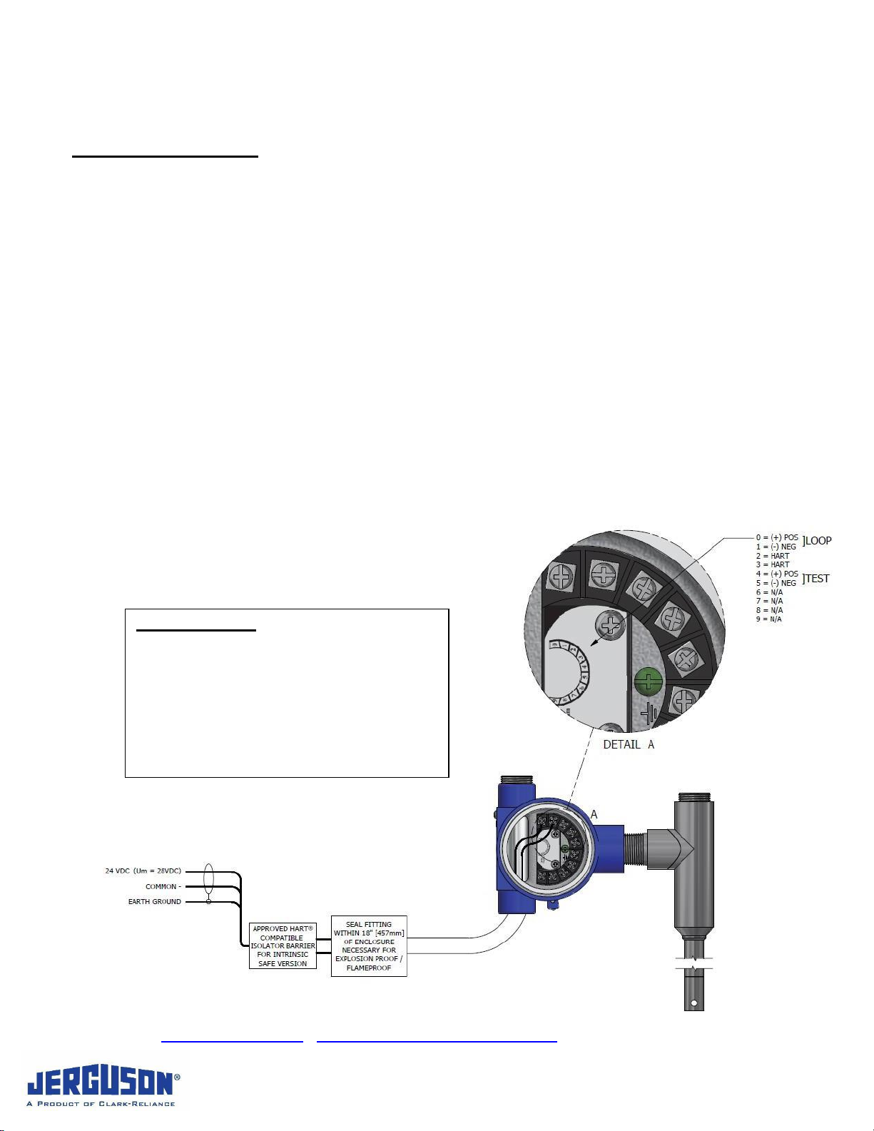
3.3 Recommended Loop Wiring (Diagram)
BEST PRACTICE:
All JMT Transmitters come with the UPPER
housing conduit entry plugged as shown in
image below. (Second entry is plugged with
temporary plastic NPT plug.) It is best practice
to connect conduit via lower available entry to
prevent water ingress. In the even unit is
flipped in field, Jerguson recommends
switching the plug to follow this orientation.
Installation, Operation, & Maintenance Instructions
IOM J500.35
2021.04
JMT
www.Jerguson.com ● JergusonApp@clark-reliance.com ● +1.440.572.1500
8
Section 4: Configuration
4.1 Operation Screen
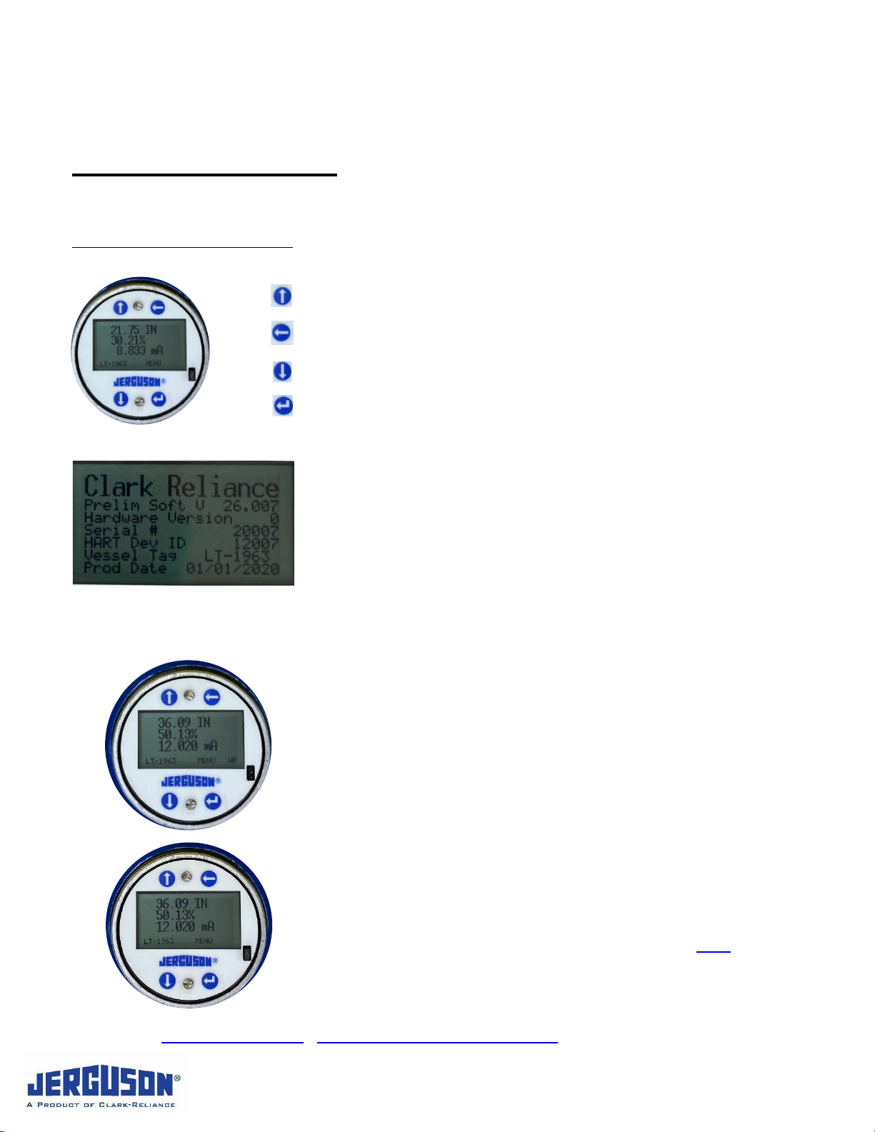
Push Button System Navigation
Up will advance the cursor up in the menu system.
Back will advance to the previous digit in a menu.
Down will advance the cursor down in the menu system.
Enter will select a menu option or advance to the next digit when
entering a value.
4.1.1 Boot-Up / Welcome Screen
Software Version: Ex.: V 29.000
Hardware Version: Ex.: 0
Serial # Ex.: 456789-01A
Hart Dev ID Ex.: 1001
Vessel Tag (if setup) Ex.: LT-1963
Production Date Ex.: 04/14/2021
4.1.2 Standard Operating Screen
Engineering Units
Inches, Millimeter, etc. (Selected in User Installation)
Percent Output
Defined as % of Level 4-20 mA
The % Output given will correspond with the mA output
current value between 4 and 20 mA
mA Output
Display of 4-20 mA analog output
Vessel Tag (if value is set –see User Installation)
WP If Write Protect Jumper is removed, bottom right will
display “WP” notification. See section 4.1.4.
Installation, Operation, & Maintenance Instructions
IOM J500.35
2021.04
JMT
www.Jerguson.com ● JergusonApp@clark-reliance.com ● +1.440.572.1500
9
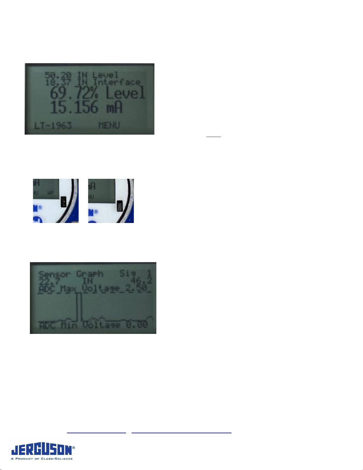
4.1.3 Standard Operating Screen –DUAL FLOAT
If you have purchased a JMT with the dual float option enabled,
it will be done so by default, and cannot be changed without
factory assistance. The unit must have two (2) floats to function
properly and will flash “LOST SIGNAL” if second float is not
installed.
The Standard Operation Screen in dual float mode will display
both the media level and the interface level, with the % of full
scale and output current of the selected output in Rerange
menu in section 4.2.6.
4.1.4 Write Protect Jumper
Jumper in place (shown at right)
Jumper removed (shown at left) and Write Protect enabled
Menu is accessible, but will all non-information selections will
display
Jumper Removed
Protection Enabled
on screen and revert back to Standard Operating Screen
4.1.5 Waveform View Pressing Back from the Standard Operating Screen will
display a graph of the signal measured by the instrument. If a
float is detected it will center on the position of that float,
showing the lowest and highest value on the graph, in units
selected in user installation. This will always be in terms of
distance from the tee/enclosure and not the reported level.
Pressing Up and Down will move the graph further and closer
to 0.0, respectively. The graph will always be scaled from 0-
2.5V, with a horizontal dotted line indicating the trigger level
(ADC Max Voltage). The detected signal must be above trigger
level for the electronics to treat a reading as a valid level signal.
A detected float will be marked with a pair of solid vertical lines, indicating the time at which the signal went
above, and then fell back below the trigger level. If a signal is detected that passes the trigger level, but is
filtered out, a pair of dotted lines will be shown on that part of the signal. The number of signals detected will
be shown in the upper right corner marked with a “Sig”. If no float is detected, the solid vertical lines of where
the float was detected previously will be displayed.
Press Back again to exit this feature.

Installation, Operation, & Maintenance Instructions
IOM J500.35
2021.04
JMT
www.Jerguson.com ● JergusonApp@clark-reliance.com ● +1.440.572.1500
10
4.1.6 Signal Lost Screen
In the event the instrument is no longer detecting a magnetic field
from the float (in single level or in dual level), “Signal Lost” will flash
between black and white on the display. The output current is set
to the NAMUR- 43 standard of either 3.5 mA, or 21 mA, based on
user selection.
See Alarms in section 4.2.10 for alarm options.
See section 5for troubleshooting lost signal.
4.2 Menu Screens
4.2.1 Accessing the Menu
Press Enter under the word “MENU” as shown here.
Push Button System Navigation
Enter will select a menu option or advance to the next digit when entering a
value.
Up will advance the cursor up in the menu system.
Down will advance the cursor down in the menu system.
Back will advance to the previous digit in a menu. If in the Standard Operation
Screen or Signal Lost Screen it will display the Sensor Output Graph of
channel 3. (See Waveform View, section 4.1.5)
Entering Values
The total number of available leading digits and decimal places will be shown for each properties value. The
cursor will begin in the ones place, indicated by the underline of the value.
For example: 001.00
When entering a property, the value displayed is the currently used value. Pressing on the Up button will
increase this value by 1. If at 9, this would increase to 10.
For example: 009.00 -> 010.00.
Pressing on the Down button will decrease this value by 1. By pressing the Back button, the cursor will
move to the next highest place value, the tens place. If cursor is in the tens place pressing back will move to
the hundreds. For example, 010.00 => 010.00. Pressing Enter will move the cursor to the next lowest place
value, from the tens place to the ones, or ones to Tenths.
For example: 001.00 => 001.00.
If in the tenths place, pressing Down will decrease the total value by 0.1.
For example: 100.0 => 099.9

Installation, Operation, & Maintenance Instructions
IOM J500.35
2021.04
JMT
www.Jerguson.com ● JergusonApp@clark-reliance.com ● +1.440.572.1500
11
Once an acceptable value has been entered, press Enter until the cursor is on the last available place. Press
Enter again and the next property in that menu subsystem will be displayed. If too large or too small a value
is entered for a parameter, it will be rejected with the maximum or minimum value in violation displayed.
Menu System Navigation
The Menu is accessed by pressing the Enter button. Details of each submenu are given in subsequent
sections.
Once you have entered a submenu it is necessary to progress through the entire submenu before exiting it. It
is not possible to use the Back button to exit a Menu.
If you leave the menu system open for 2 minutes with no inputs, it will automatically exit to the Standard
Operating Screen.
WARNING
While in the Menu System HART commands will be disabled.
4.2.2 Menu (First Screen)
Device Info
User Installation
Rerange
Flip Transmitter
One Point Calibration
Calibration
Alarms
4.2.3 Menu (Second Screen)
Filters
Reset Factory Configuration
Factory Configuration (Factory Password Protected)
Diagnostics
Exit Menu

Installation, Operation, & Maintenance Instructions
IOM J500.35
2021.04
JMT
www.Jerguson.com ● JergusonApp@clark-reliance.com ● +1.440.572.1500
12
4.2.4 Device Info
This will display the device information and configuration data, as well as whether the calibration has been
modified since being shipped from the factory.
Boot/Welcome Screen
Software Version
Hardware Version
Serial#
HART ID
Vessel Tag (if entered)
Production Date
Instrument Config
Single/Dual Float
Engineering Units Selected
Sensor Length
4mA setting (LRV)
20mA setting (URV)
Gain %
Trigger V (Voltage)
Min Signal Width
Level Offset (if entered)
Top/Bottom Mount
Calibration Status (Sensor/Loop)

Installation, Operation, & Maintenance Instructions
IOM J500.35
2021.04
JMT
www.Jerguson.com ● JergusonApp@clark-reliance.com ● +1.440.572.1500
13
4.2.5 User Installation Level Units
The JMT will come preprogrammed to the desired user
installation. If however it is desired to change any of these
settings, they are done so through this menu.
Level Units
Selection between units, if this is changes it will propagate, and
show the units across the values to be entered for all properties.
Inches XXX.XX (Two Decimal Places)
Feet XX.XXX (Three Decimal Places)
Millimeters XXXXXX (No Decimal Place)
Centimeters XX.X (One Decimal Place)
Meters X.XXX (Three Decimal Places)
1/16 Of a FootXXXX.XX (Two Decimal Places)
Use Up and Down to select desired Engineering Units to be
displayed. Then press Enter to move to next screen.
Level Offset
This is a user value for if they have a need to report a level
offset from the measured level. Typically, this is the distance
from the lowest point the sensor can measure, to the bottom of
the tank, or any zero-reference point lower than end of the
Magnetostrictive sensing element. Use Up/Down (or Back to
change position) and Enter to move to next screen.
Note: Offset cannot be Sensor Length.
Vessel Tag
This is an 8-character tag that can be used to name the
instrument for the operator. If set, this tag will be displayed on
the Main Operating Screen. This is a distinct tag from the
HART tag, which can only be set via HART.
Long press of the Up or Down buttons scrolls quickly through
the alpha-numeric selection. Enter sets each place’s value.
Once tag is set, press Enter as needed to close out the screen,
Note that the vessel tag will only be displayed if the first
character is changed.
Installation, Operation, & Maintenance Instructions
IOM J500.35
2021.04
JMT
www.Jerguson.com ● JergusonApp@clark-reliance.com ● +1.440.572.1500
14
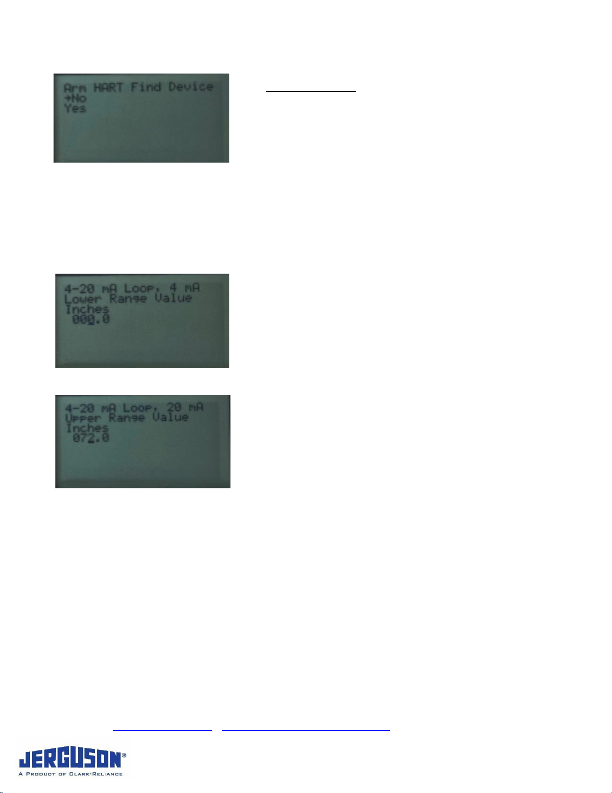
Arm HART Device
Standard HART Command to set bit to be “found” by
MASTER/HOST.
4.2.6 Rerange
NOTE: If Dual Float setup, first screen will be choice between Interface and Media Level. Subsequent
screens are the same.
Enter the value desired for 4mA reading. Note this should be
measured from the dead band set at the factory and marked on
the sensor. Typically, the Zero is 000.0 for measuring the full
(default) span.
A transmitter rerange can be done to change the measured level
for which the output will be 4 and 20 mA. It will not affect the
level measurement reported in engineering units selected
(inches, millimeters, etc.), just the current and percentage
output. The units for both will be based on those set in User
Installation.
Enter the “span” for “full” value. Typically, this is equal to the
measuring range as ordered.
Reminder: Reranging the 4mA/20mA will change the % and mA
readings on the display, but NOT the engineering units. For example,
on a 96” max measuring range unit, moving the 0” to 24” and the
full/span from 96” to 84” would have the following effect: from 0” to 24”,
the engineering units would rise as the float does, but the mA output
would be 3.8mA (empty saturation) with a corresponding negative %.
At 24”, the mA output and % would be 4mA and 0%, respectively, and
begin to rise linearly until 20mA/100% at 84”. Above 84”, the mA output
would rise to full saturation 20.5mA with a corresponding 100+% value.
(Exact negative and 100+% driven by length of span and differ by unit.)

Installation, Operation, & Maintenance Instructions
IOM J500.35
2021.04
JMT
www.Jerguson.com ● JergusonApp@clark-reliance.com ● +1.440.572.1500
15
4.2.7 Flip Transmitter
Select Top or Bottom Mount (Head Location)
CAUTION:
For accurate measurement, it is recommended you perform a
Trim function as seen in section 4.2.8.
4.2.8 One Point Calibration
Note: The JMT is designed such that it should never require recalibration. The below actions are to
be utilized for very specific reasons.
Two forms of One Point Calibration are available. Calibration is
an emergency procedure to be used only if moving the
instrument electronics/module between two installations. See
Calibration/Level Sensor 2Pt Cal for more accurate calibration.
Trim is used either after performing Flip Transmitter, or if the
entire instrument and probe is being moved from one installation
to another.
See section 5for Troubleshooting.
Calibration
This is the overall length of the sensor. Only used if Calibration
has been selected.
4-20 mA Loop, 4mA lower Range Value
This will set the measured level at which the output is
4mA. It will be done in the units set in User Installation.
4-20 mA Loop, 20mA upper range value
This will set the measured level at which the output in
20mA. The maximum value for this is the Sensor Length
parameter.
Perform Float Position Calibration
Note: this is same as Trim command from upper menu.
You will be prompted to decide if this step is necessary; No
reverts back to menu.
Installation, Operation, & Maintenance Instructions
IOM J500.35
2021.04
JMT
www.Jerguson.com ● JergusonApp@clark-reliance.com ● +1.440.572.1500
16
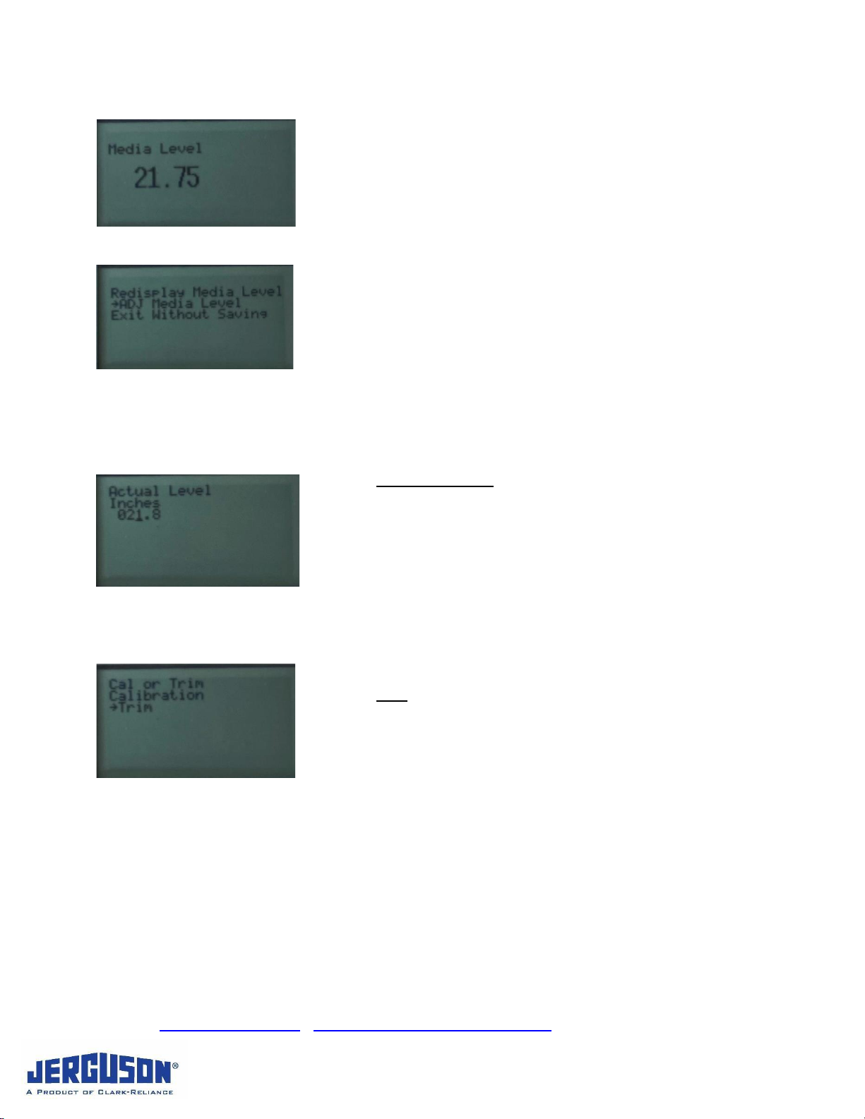
If you select Yes, the currently measured level will be displayed,
After a few seconds, the user will be prompted to Redisplay
Media Level, ADJ (Adjust) Media Level, or Exit Without
Saving.
If you agree with the output, simply Exit Without Saving. To
calibrate the output to a different measurement, select ADJ
Media Level.
ADJ Media Level
Unit will show current media level. Use buttons to change value
to desired reading. Enter value. Upon completion, you will be
reverted back to Main Menu.
Trim
This function is required flipping the transmitter or is moving the
entire unit from one installation (chamber) to another. See
Perform Float Calibration above.
Installation, Operation, & Maintenance Instructions
IOM J500.35
2021.04
JMT
www.Jerguson.com ● JergusonApp@clark-reliance.com ● +1.440.572.1500
17
4.2.9 Calibration
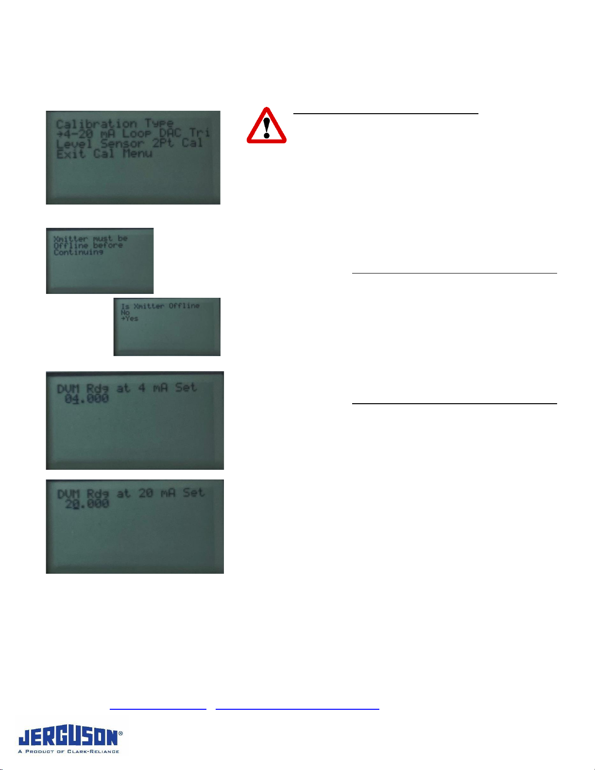
DAC Trim (Digital to Analog Converter)
The purpose of the DAC trim is to calibrate the current
output of the transmitter. This process should only be
done with a NIST (National Instrument of Standard and
Technology) traceable multimeter, AND the transmitter must be
offline from any control processes.
First connect your NIST Traceable Multimeter in series with the
Loop power on the Negative side. Select 4-20 mA Loop DAC
Trim.
Press Enter and the transmitter output will go to 4mA, and
prompt to enter the measured current output on the multimeter.
NOTE: These should be very subtle changes, ex 4.000 may
read 4.004 (requiring 4.004 to be entered)
Large changes would indicate a problem with set up or even
possible damage to the JMT
Once complete, the transmitter output will go to 20mA, and
prompt to enter the measured current output on the multimeter.
Once complete, it will revert back to the Calibration menu.

Installation, Operation, & Maintenance Instructions
IOM J500.35
2021.04
JMT
www.Jerguson.com ● JergusonApp@clark-reliance.com ● +1.440.572.1500
18
Level Sensor 2Pt Cal
The instrument will come calibrated from the factory and should
not require a two-point calibration. However, it may become
necessary if the instrument is installed in an area with a very
high ambient air temperature at the probe. This requires the
ability to move the float level.
A Two Point Calibration may be accessed through the
Calibration Menu. You will be prompted to verify that the
transmitter is offline, and that the process is most accurate if the
two points used are greater than 10% of the probe length apart.
The two points can go in order from higher to lower, or lower to
higher levels.
It will ask if you want to continue. No reverts to the Calibration
menu. Yes will have you set the float at point #1. You will need
to know the position of the float and it must be stable. When the
float is at point #1 and stable, press Yes. (120) Measurements
will be taken to provide the highest possible accuracy
calibration. If a stable signal is not detected, you will be
prompted to set the Gain and Trigger Level. (See section 5
Troubleshooting)
If a stable signal is detected, you will be prompted to enter the
actual level of the float.
Do so and then move the float to point #2 and repeat the
process. Remember it must be at least 10% the Overall Length
of the sensor different from point #1. If the points are too close,
the calibration will fail.
After entering the float position at the second point, a verification
process will begin. If the values are too close together the
calibration will fail. If the verification of the calibration is correct,
you may exit the process finishing calibration. This verification
process is used to prevent incorrect calibrations from entering
the instrument. If not you may re-attempt verification, or redo the
calibration.

Installation, Operation, & Maintenance Instructions
IOM J500.35
2021.04
JMT
www.Jerguson.com ● JergusonApp@clark-reliance.com ● +1.440.572.1500
19
4.2.10 Alarms
There are four possible alarm conditions available in the event
that the float is not detected.
3.5 mA –Current output will go to 3.5 mA if a float is not
detected.
21.0 mA –Current output will go to 21.0 mA if a float is
not detected.
Hold last then 3.5 mA –Current output will go to 3.5 mA
if a float is not detected after waiting a user specified
number of second (Up to 1000 seconds).
Hold last then 21.0 mA –Current output will go to 21.0
mA if a float is not detected after waiting a user specified
number of seconds (Up to 1000 seconds).
4.2.11 Filters
Several filters are automatically used by the JMT to prevent erroneous signal measurement. These filters
may be adjusted as described in the Measurement Troubleshooting section in Section 5
Troubleshooting. There is no need to do so under normal operation.
Rate of Change Filter
The Rate of Change Filter is designed to remove random noise
the sensor may detect from vibrations or electromagnetic
interference. The operating principle is that there is a maximum
speed at which the float can move, meaning the measured level
can only change so much between each measurement. Each
measurement is compared to the one before it, and if a signal is
detected outside what this filter would allow it is ignored,
allowing the true signal from the float to be detected.
The Rate of Change Filter is set with both a distance
measurement, and time requirement.

Installation, Operation, & Maintenance Instructions
IOM J500.35
2021.04
JMT
www.Jerguson.com ● JergusonApp@clark-reliance.com ● +1.440.572.1500
20
Smart Smoothing
The Smart Smoothing Filter is designed to smooth out
variations in the measured level from the float rotating or
leaning in the chamber. It works by averaging the
previous measurements over the specified # of seconds
and calculating that as the measured level. The factory
default setting of 3 seconds.
If the float were to move extremely rapidly (for example
by hand) this would show some delay in updating
measured level.
Media Level Dampening
Damping is available on the Current Output, this will
damp the change in output current, not in the actual
measurements.
Pulse Width, Gain and Trigger Level Filter
The pulse width filter is designed to remove signals
detected by the sensor that do not match the signature of
the float of the instrument. A float will provide a large,
long signal, while something like spurious electrical noise
will provide a short signal. The pulse width filter
calculates the amount of time the signal is above the
specified trigger voltage and rejects it if it is too short.
This, in combination with the Rate of Change Filter
makes it extremely difficult for any electromagnetic noise
to affect the instrument.
Three channels will be available. Channel 1 and Channel
2 are the output of the two individual crystals in sensor.
Channel 3 is their combined input which is what is used
by the level measurement instrument.
Table of contents
Other Jerguson Industrial Equipment manuals


