Jerguson LUMASTAR EPL-100 Assembly instructions

1 of 4
Specialists in Liquid Level Indication
STORAGE and HANDLING
The Jerguson LED Explosion Protected
Illuminator meets or exceeds all applicable
specifications when shipped from the factory.
All units should be inspected upon receipt to ensure
that no damage has been incurred during transit. If
there has been damage, a claim should be filed with
the carrier immediately. Unit should be stored in an
area protected from the elements and corrosive
fumes, in a secure manner where they can neither
fall, nor be struck by other objects. Care should be
taken to protect the window and the end connections
from damage. Avoid placing any objects directly
on the light at any time.
COMPONENTS
There are three main components that make up the
LED illuminator: the light strip, the power supply,
and the cable connecting these two main pieces.
The cable may have more than one piece depending
on the required distance between the illuminator and
the power supply. The power supply is constructed
of aluminum, aluminum conduit sealing device and
a stainless steel I.S. connector. The light bar is
constructed of aluminum, stainless steel, glass and
silicone. Questions regarding acceptable
applications should be directed to The Clark-
Reliance Corporation.
INSTALLATION
CAUTION: All lights are tagged with the
service conditions for that particular unit. These
specifications are located on the Jerguson tag on
the power supply housing, and are contained in
the “Specifications” section of this manual. Do
not use or refer to specifications listed on red
label on the power supply housing. They are
specifications for generic use. Review the ratings
prior to installation and again prior to start-up,
to ensure proper operation in the installed
environment. Should there be any doubt as to
the applicability of a unit for the installed
environment, consult the factory before placing
the unit into service.
Note: All installation steps should be
performed by a qualified technician and should
be executed in accordance with all applicable
national and local codes.
The light and power supply should be checked to
ensure that they contain no foreign matter, and that
the end connections are clean, undamaged, and in
line with existing conduit.
Step by step instructions:
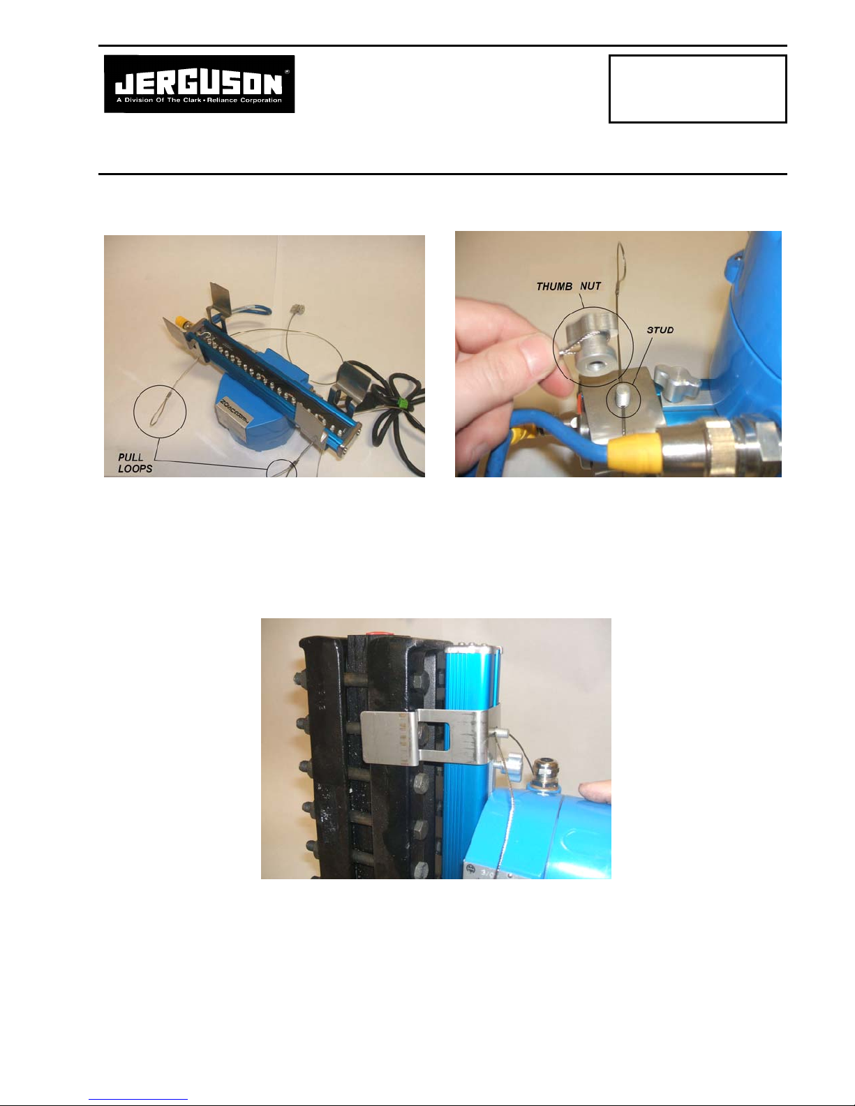
1) Refer to J500.33.A1 for bracket mounting
instructions.
CAUTION: Before working with power supply,
verify that the area is free of flammables and AC
power circuit is off.
2) Loosen cover locking screw and open the cover
of the power supply housing. Insert the AC
Line wires into the housing and connect to the
“AC IN” terminal block. A ground screw is
located inside the enclosure if required.
CAUTION: The DC output is pre-wired. If this
connection is removed during installation,
reconnect the “AC IN” and “DC OUT” to the
proper positions. Failure to do so will result in
permanent damage to the power supply.
3) If the cable will not reach the power supply,
contact your local representative for the
required extension cable.
4) Replace the cover on the power supply housing.
5) Switch “ON” the power supply making sure the
Illuminator is functioning properly, with all
LED’s illuminated.
6) If the LED’s do not illuminate, remove the
cover on the power supply once the power as
LUMASTAR™ EPL-100
INSTALLATION, OPERATING &
MAINTENANCE
INSTRUCTIONS FOR
ATEX UNITS
Section: J500
Bulletin: J500.33
Date: 01-10-12
Supersedes: 09-11-06

2 of 4
been turned on. An LED will be lit if it is wired
correctly. See Figure 1, Detail “A”
7) If the LED in the power supply is not lit, check
the power source and the connection before
continuing.
Any additional components must be installed prior
to the customer’s sealing fitting.
FUSE REPLACEMENT
This power supply is fused for AC protection. In the
event of a large voltage surge, the fuse may release,
causing no output voltage. Replace fuse, referring
to Clark-Reliance p/n E-F-DIN-F400MA as shown
on Page 4.
1) Loosen cover locking screw and open the cover
of the power supply housing.
2) Remove and replace bad fuse. Refer to Figure 1
for fuse location.
REPLACING POWER SUPPLY
1) Loosen cover locking screw and open the cover
of the power supply housing. Disconnect AC
power in and remove AC wires from enclosure.
2) Remove assembly from gage and relocate to
desired work area.
3) Disconnect power cable between power supply
and light bar assembly.
4) Trim gasket material at top end cap to match
slot opening and slide out bracket and mounting
hardware.
5) Loosen power supply screws and slide power
supply off light bar assembly.
6) Slide new power supply onto light bar
assembly.
7) Insert bracket and mounting hardware for top
bracket back into slot.
8) Securely tighten the power supply screws and
the top bracket screw.
9) Install power cord between power supply and
light strip making sure connectors are fully
connected.
OPERATION
The LED illuminator can run continuously.
The operating life of LED lights can exceed
100,000 hours under normal conditions.
ROUTINE MAINTENANCE
Keep window on the front of the light clean
using commercial glass cleaners, such as Windex ®
or similar. Never use harsh abrasives, wire brushes,
metal scrapers, or any material that could scratch
the window. The window may be cleaned while the
unit is in operation.
The light may be removed while the unit is in
operation during inspection or maintenance of the
customer’s gage glass. The Illuminator may also be
disconnected from the power supply, if desired.
Disconnect the cord at the supplied screw connector
adjacent to the power supply. The plant power
going to the power supply does not need to be
disconnected.
SPECIFICATIONS
Power Supply: 120 or 240 VAC @ 50-60 Hz
Power < 750 mA @ 120 VAC
Consumption: < 375 mA @ 240 VAC
Est. Life: 100,000 Hours (continuous)
Wire Size: Min 1mm2/ Max 2.5mm2
Max dist. from
power supply to light: 15 M
Ambient Temperature: -40 C/77 C
Electrical Connection: 1/2” FNPT

3 of 4
Figure 1: Wiring Instruction
CAUTION: Incorrectly wiring the AC input to the DC output
will cause permanent damage to the power supply and result in
the ignition of hazardous atmospheres.
Replacement Parts
Item Part Numbe
r
Description
1 S24287-115V 115 VAC ATEX Power Supply Board/Bracket Sub-Assembly (See Note Above)
2 S24287-230V 230 VAC ATEX Power Supply Board/Bracket Sub-Assembly (See Note Above)
3 S24196-EPL-115V 115 VAC ATEX Power Supply with Enclosure (Includes All Items Illustrated Above)
4 S24196-EPL-230V 230 VAC ATEX Power Supply with Enclosure (Includes All Items Illustrated Above)
5 E F DIN F400MA 400mA 5x20mm DIN Fuse
* When replacing the Light Bar assembly the # - # portion of the part number will be determined from the
original order by The Clark-Reliance Corporation.
POWER SUPPLY/BRACKET SUB-ASSEMBLY

4 of 4

EC Declaration of Conformity
Manufacturer: The Clark-Reliance Corporation
16633 Foltz Parkway
Strongsville, OH 44149
QAN Certificate Number ITS09ATEXQ6353 issued by
Intertek Testing & Certification
Declaration that the equipment listed below is in conformity with the provisions of the ATEX directive
94/9/EC including all current amendments.
Model # LumaStar or EPL-100
Certificate # FM06 ATEX0019
The following standards have been applied: EN 60079-0, EN 60079-1, EN 60079-11
Authorized
Signature(s):___________________________________________
Engineering Manager Date
:
MRfQ Date

Specialists in Liquid Level Indication
*NOTE: Identify your bracket type. Confirm the bracket style matches that in the below pictures.
Figure 1
1) Align Lumastar assembly with rear (side with bolt heads) of gauge. Loosen bracket thumb nuts and adjust the
position of the brackets to line up with their respective bolts on the gauge as shown in Figure 1. Tighten the
thumb nuts to secure in place. When possible, use the 2nd set of bolts from the edge of the cover plate.
Figure 2 Figure 3
2) Align one side of the brackets as shown in Figure 2, so that the clip of the brackets are gripping around the side
of the gauge. Roll the entire assembly over until it is flush with the rear flat of the gauge and press until the
bracket clips have locked into place as shown in Figure 3.
Page 1 of 1
LUMASTAR™ EPL-100
INSTALLATION, OPERATING &
MAINTENANCE
INSTRUCTIONS FOR
ATEX UNITS
Section: J500
Bulletin: J500.33.A1
Date: 08-28-12
Supersedes: 01-09-12

Specialists in Liquid Level Indication
*NOTE: Identify your bracket type. Confirm the bracket style matches that in the below pictures.
Figure 1 Figure 2
Step 1: Check to make sure brackets are properly assembled on the illuminator. The cable should be fed through the stud
protruding from behind the illuminator, locking in the bracket as shown above in Figure 2. One end of the cable should
be crimped into an oval for pulling leverage and the other should be crimped securely around a thumb nut.
Figure 3
Step 2: Press LumaStar assembly against rear of gauge as shown in Figure 3, aligning the bracket cutouts over the gauge
bolt heads as shown. Align the brackets with the 2nd set of bolts in from each end of the gage, when possible.
Page 1 of 3
LUMASTAR™ EPL-100
INSTALLATION, OPERATING &
MAINTENANCE
INSTRUCTIONS FOR
ATEX UNITS
Section: J500
Bulletin: J500.33.A2
Date: 08-28-12
Supersedes: NEW

Figure 4 Figure 5
Step 3: While holding the top bracket in place, grab the thumb nut end of the cable, wrap around entire gauge and thread
onto the stud until the bracket is secure. When wrapping the cable around the gauge, make sure to feed the cable above
the bolt as shown above in Figure 5. Snug the cable and secure the thumb nut, but do not fully tighten the thumb nut at
this time
Figure 6
Step 4: Align bottom bracket, using the 2nd bolt if possible. Wrap thumb nut end of the cable around the entire gauge and
begin to thread. Pull the cable loop as tight as possible and fully tighten the thumb nut down as shown in Figure 6. The
lower bracket should now be tight and secure.
Page 2 of 3

Figure 7
Step 5: After the lower bracket has been tightened, go back to the top bracket and loosen the thumb nut enough to allow
the cable to slide through freely. Pull cable as tight as possible, and fully tighten thumb nut as shown in Figure 7.
.Figure 8 Figure 9
Step 6: The LumaStar is now properly installed. Feel free to tuck any excess cable inside itself or allow it to hang freely.
This adjustable assembly is appropriate for any gauge with a cover width not exceeding 4.375 inches (111 mm).
Page 3 of 3
Other manuals for LUMASTAR EPL-100
2
Table of contents
Other Jerguson Industrial Equipment manuals