Pura UVSS-6 User manual

INSTALLATION MANUAL & OWNER’S GUIDE
Stainless Steel Ultraviolet Water Purification S stem
UVSS-6
UVSS-10
UVSS-15
UVSS-6M
UVSS-10M
UVSS-15M
#51975 Rev. 10/08

Safet Instructions
WARNING
To guard against injury, basic safety precautions s ould be observed, including t e following:
1. READ AND FOLLOW ALL SAFETY INSTRUCTIONS.
2. CAUTION - Always disconnect power before servicing.
3. DANGER - To avoid possible electric s ock, special care s ould be taken since water is present near electrical equip-
ment. Unless a situation is encountered t at is explicitly addressed by t e provided maintenance and troubles ooting
sections, do not attempt repairs by yourself, refer to an aut orized service facility.
4. Carefully examine t e disinfection system after installation. It s ould not be plugged in if t ere is water on parts not
intended to be wet suc as, t e ballast or lamp connector.
5. Do not operate t e disinfection system if it as a damaged cord or plug, if it is malfunctioning or if it as been dropped
or damaged in any manner.
6. Always disconnect water flow and unplug t e disinfection system before performing any cleaning or maintenance activ-
ities. Never yank t e cord to remove from an outlet; grasp t e wall plug and pull to disconnect.
7. Do not use t is disinfection system for ot er t an intended use (potable water applications). T e use of attac ments
not recommended or sold by t e manufacturer/distributor may cause an unsafe condition.
8. Intended for indoor use only. Do not install t is disinfection system w ere it will be exposed to t e weat er or to tem-
peratures below freezing. Do not store t is disinfection system w ere it will be exposed to t e weat er or to tempera-
tures below freezing unless all water as been drained from it and t e water supply as been disconnected.
9. Read and observe all t e important notices and warnings on t e water disinfection system.
10. If an extension cord is necessary, a cord wit a proper rating s ould be used. A cord rated for less Amperes or Watts
t an t e disinfection system rating may over eat. Care s ould be taken to arrange t e cord so t at it will not be tripped
over or pulled. Circuit breaker must not exceed power cord current rating (ie - 15A for Nort American NEMA 5-15P).
11. SAVE THESE INSTRUCTIONS
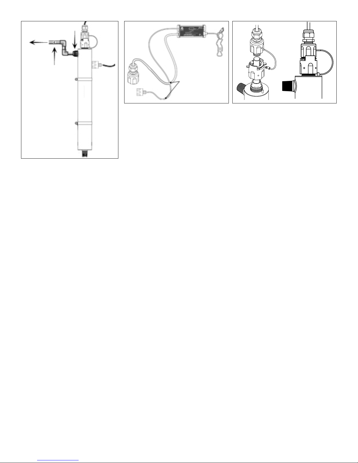
WARNING: T e UV lig t given off by t is unit can cause serious burns to unprotected eyes and skin. Never look directly
at an illuminated UV lamp. W en performing any work on t e UV disinfection system always unplug t e unit first. Never
operate t e UV system w ile t e UV lamp is outside of t e UV c amber.
You ave purc ased one of t e most tec nologically
advanced Ultraviolet Water Treatment System available
anyw ere in t e world. It as been designed wit you, t e
consumer, in mind. PURA®products are lig tweig t, easy
to use, and simple to maintain. PURA products will pro-
vide you wit ealt y, clean drinking water for years to
come.
What is Ultraviolet?
Ultraviolet (UV) lig t from t e sun as long been known
for its ability to destroy microorganisms. However, it as
only been in recent years t at equipment producing UV
lig t as been manufactured for residential use.
UV energy is produced by low-pressure mercury vapor
enclosed in a tubular lamp. W ile a UV lamp resembles a
standard fluorescent lamp, it is similar in appearance only.
Energy produced by t e UV lamp as t e ability to
destroy microorganisms t at can live in water. T ere are
five major groups of microorganisms t at are altered by a
specific spectrum of ultraviolet lig t: viruses, bacteria,
fungi, algae, and protozoa.
W en t ese microbes are exposed to t e proper amount
of UV energy, t eir DNA structure is scrambled, and t ey
are unable to reproduce. Since t e cell is now sterile or
dead, it is no longer a t reat.
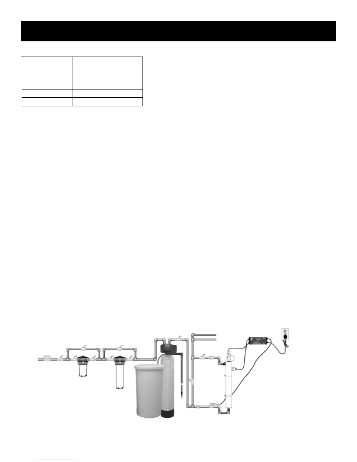
PURA S stems
PURA recommends t at all UV systems include pre-fil-
ters to process t e water before it reac es t e UV lamp.
T is will ensure t at maximum UV exposure is ac ieved.
PURA Ultraviolet Water Treatment Systems are designed
for indoor use only.
PURA Systems are designed to provide complete water
treatment in a compact, easy-to-use package. Please fol-
low t e directions in t is Guide exactly w en installing
your PURA System to ensure t at it operates correctly.
Specifications
Item # Model# Flow Rate** Flow Rate** Flow Rate** Power Lamp Inlet/ UV Chamber Size Control Box Size eight
@ 16 mJ/cm2@ 30 mJ/cm2@ 40 mJ/cm2Consumption atts Outlet (D x L) (L x x H) lbs (kg)
usgpm (L/min) usgpm (L/min) usgpm (L/min) atts Size inches (cm) inches (cm)
8750 UVSS-6 11 (41.63) 6 (22.71) 4.5 (17) 30 25 3/4" NPT 2.5"(6.35) x 22.07"(57.6) 7.3"(18.54) x 3.15"(8) x 2.52"(6.4) 7 (3.18)
8751 UVSS-10 20 (75.7) 10 (37.85) 7.7 (29.14) 46 37 3/4" NPT 2.5"(6.35) x 35.7"(90.6) 7.3"(18.54) x 3.15"(8) x 2.52"(6.4) 11 (5)
8752 UVSS-15 29 (109.76) 15 (56.77) 11 (41.63) 48 39 1" NPT 3.5"(8.9) x 38.1"(96.7) 7.3"(18.54) x 3.15"(8) x 2.52"(6.4) 14 (6.36)
8753 UVSS-6M 11 (41.63) 6 (22.71) 4.5 (17) 30 25 3/4" NPT 2.5"(6.35) x 22.07"(57.6) 8.3"(21) x 3.15"(8) x 2.52"(6.4) 8 (3.63)
8754 UVSS-10M 20 (75.7) 10 (37.85) 7.7 (29.14) 46 37 3/4" NPT 2.5"(6.35) x 35.7"(90.6) 8.3"(21) x 3.15"(8) x 2.52"(6.4) 12 (5.45)
8755 UVSS-15M 29 (109.76) 15 (56.77) 11 (41.63) 48 39 1" NPT 3.5"(8.9) x 38.1"(96.7) 8.3"(21) x 3.15"(8) x 2.52"(6.4) 15 (6.81)
1
*Flow r tes st ted t 96% UVDEOL. The m nuf cturer reserves the right to m ke product improvements which m y devi te from the specific tions nd
descriptions st ted herein, without oblig tion to ch nge previously m nuf ctured products or to note the ch nge.

Conditions For Use
Water quality is extremely important for t e optimum performance of your UV system. T e following levels are recommend-
ed for installation:
If your water c emistry contains levels in excess of t ose mentioned above, proper pre-treatment is recommended to cor-
rect t ese water problems prior to t e installation of your UV disinfection system. T ese water quality parameters can be
tested by your local dealer, or by most private analytical laboratories. Proper pre-treatment is essential for the UV dis-
infection system to operate as intended.
Installing Your UV Disinfection S stem
CAUTION
Electronic ballast must be connected to a grounded receptacle and t e lamp connector ground wire connected to t e stain-
less steel reactor c amber.
• T e disinfection system is designed to be mounted eit er orizontally or vertically at t e point-of-use or point-of-entry
depending on t e specific flow rate of t e unit.
Note: T e ideal installation is vertical wit t e lamp connector at t e top. T is is to prevent water damage from occur-
ring on t e lamp pins and lamp connector.
• T e ballast s ould be mounted eit er above or beside t e reactor c amber. Never mount vertically wit AC connector
at top of ballast to prevent moisture from running down cordage and causing a potential fire azard. Drip loops in all
cordage connected to ballast controller is ig ly recommended (see Figure 1D).
• T e complete water system, including any pressure or ot water tanks, must be sterilized before start up by flus ing
wit c lorine ( ouse old bleac ) to destroy any residual contamination (see page 4).
• For safety purposes, t e disinfection system s ould be connected to a ground fault interrupt circuit.
• T e disinfection system is intended for indoor use only, do not install disinfection system w ere it may be exposed to
t e outdoor weat er.
• Install t e disinfection system on cold water line only.
• If treating t e entire ouse, install t e disinfection system before any branc lines.
• A 5 micron sediment filter must precede t e disinfection system. Ideally, t e disinfection system s ould be t e last
treatment t e water receives before it reac es t e faucet.
2
Note: The UV lamp inside the disinfection s stem is rated at an effective life of approximatel 9000 hours. To
ensure continuous protection, replace the UV lamp annuall .
Typical Installation
Figure 1 - Typical installation of disinfection system and t e related components t at may be used for t e installation
Iron (Fe) < 0.3 ppm (0.3 mg/L)
H rdness* < 7 gpg (120 mg/L)
Turbidity < 1.0 NTU
M ng nese (Mn) < 0.05 ppm (0.05 mg/L)
T nnins < 0.1 ppm (0,1 mg/L)
UV Tr nsmitt nce > 75%**
*Where tot l h rdness is less th n 7 gpg, the UV unit should oper te efficiently provided the qu rtz
sleeve is cle ned periodic lly. If tot l h rdness exceeds 7 gpg, the w ter should be softened.
**C ll customer service for recommend tions on pplic tions where UVT < 75%.
5 micron
Sediment
Filtr tion
Byp ss
Assembly
Hot w ter distribution
Cold w ter distribution

3
1. T e use of a bypass assembly is recommended in case t e system requires
‘off-line’ maintenance. If t is is t e case, it must be noted t at t e system will
require supplementary disinfection of t e distribution system if any water is
used during t is bypass condition. In addition, during bypass, t e water will
NOT be disinfected until suc time as t e system is sanitized and returned to
service. Please refer to t e complete disinfection procedure as outlined on
page 4 of t is document. If t e water is to be offline, t e water must be boiled
for twenty minutes prior to consumption.
2. Select a suitable location for t e disinfection system and its related compo-
nents. As it is recommended to install a ground fault protected circuit (GFCI),
make sure t at t is is taken into consideration prior to any installation. T e
system can eit er be installed vertically (inlet port at t e bottom) (Figure 1A),
or orizontally (Figure 1B), owever t e vertical installation is t e most pre-
ferred met od. W en selecting a mounting location, you must also leave
enoug space to allow for t e removal of t e UV lamp and/or quartz sleeve
(typically leave a space equal to t e size of t e reactor c amber itself).
Pre-Installation Instructions
T e figure below s ows t e proper water flow for orizontal or vertical instal-
lation. Make certain t at your unit and t e inlet and outlet pipes
are in t e rig t position for eit er orizontal or vertical installa-
tion
3. Mount t e system to t e wall using t e supplied clamps. Various connection met ods can be used to connect t e water
source to t e system, owever union type connectors are recommended. T e use of a flow restrictor device is strong-
ly recommended w en installing your system in order to maintain t e manufacturers rated flow rate. T e flow restric-
tor s ould be installed on t e outlet port and is designed to be installed in one direction only. Ensure t at t e flow of
t e water matc es t e flow direction as indicated on t e flow restrictor (Figure 1C). DO NOT SOLDER CONNECTIONS
WHILE ATTACHED TO THE SYSTEM AS THIS COULD DAMAGE THE O-RING SEALS.
4. Mount t e controller orizontally on t e wall, near t e reactor c amber. Ideally place t e controller above t e reactor
and away from any water connection point, to prevent any water from potentially leaking onto t e controller by means
of a leak at a connection point or a ‘sweating’ system. Make sure you allow for a ‘drip-loop’ (Figure 1D) on t e lamp,
sensor and power cord (prevents water from potentially entering t e controller). Affix t e green ground wire to t e
grounding lug at t e top of t e reactor vessel and securely fasten wit t e lugnut provided (Figure 1E).
5 Install t e UV lamp and sensor as outlined on pages 5-6.
6. W en all plumbing connections are made, slowly turn on t e water supply and c eck for leaks. T e most likely cause
for leaks is from t e o-ring seal. In case of a leak, s ut water off, drain cell, remove t e retaining nut, wipe t e o-ring
and t reads clean and re-install.
7. Once it is determined t at t ere are no leaks, plug t e system into t e ground fault interrupter circuit, and c eck con-
troller to ensure t e system is operating properly. T e controller is designed to detect bot power to t e system and
lamp illumination. It is important to NEVER LOOK DIRECTLY AT THE GLOWING UV LAMP.
8. Allow t e water to run for a few minutes to clear any air or dust t at may be in t e reactor.
PLEASE NOTE: W en t ere is no flow, t e water in t e cell will become warm, as t e UV lamp is always on. To remedy
t is, run a cold water tap anyw ere in t e ouse for a minute to flus out t e warm water.
Figure 1A
Figure 1B
Min. Cle r nce Equ l
to Unit Over ll Length
Unit Over ll Length Min. Cle r nce Equ l
to Unit Over ll Length
Unit Over ll Length
IMPORTANT: For vertical installation, the inlet is at
the bottom and the outlet is near the top of the disin-
fection chamber. For horizontal installation, pay
careful attention to the diagram for flow direction.
Correct Installation
Incorrect Installation
GFCI Receptic l
GFCI
Receptic l

4
Figure 1C
Figure 1E
Flow
Flow
Restrictor
Flow direction must
be the s me s
rrow on flow
restrictor.
Outlet Port
on Cell
Disinfection Procedure
UV disinfection is a p ysical disinfection process and does not add any potentially armful c emicals to t e water. As UV
does not provide a disinfection residual, it is imperative t at t e entire distribution system located after t e UV be c emi-
cally disinfected to ensure t at t e water is free from any bacteriological contaminants. T e disinfection process must be
performed immediately after t e UV unit is installed and repeated t ereafter w enever t e UV is s ut down for service,
wit out power, or inoperative for any reason. T e procedure for sanitizing t e plumbing system is readily accomplis ed as
follows:
1. S ut off t e upstream water supply t at feeds water into t e reactor c amber and depressurize water system. Remove
t e pre-filter cartridge and fill t e sump wit 1-2 cups of ouse old (5.25%) bleac (c lorine) - Do NOT use ydrogen
peroxide. At all times during t e process, make sure t e UV unit (and lamp) is turned on and operational!
2. Repressurize water system, open eac faucet and allow cold water to run until you smell c lorine, s ut t e faucet off
and t en repeat t e process for eac faucet, including ot water. You must ensure t at all taps, including outside faucets,
dis was ers, s ower eads, was ing mac ines, connections to refrigerators, toilets, etc., pass c lorinated water.
3. Once all t e locations ave passed t e c lorine disinfection solution, you will need to leave t e solution sit for a peri-
od of 20 - 30 minutes. Reinstall t e pre-filter cartridge into t e filter and t en flus t e c lorine solution from t e sys-
tem until no c lorine smell is detectable. Make sure t at eac fixture t at was disinfected in step 2 is completely flus ed
of t e c lorine solution as t e consumption of t is water is not advised due to t e extremely ig concentration of c lo-
rine. It is important to remember t at in t e event t at a UV is briefly s ut down for routine cleaning or during power
interruptions w ere water could ave passed t roug t e system, t e aforementioned procedure must also be fol-
lowed.
Note A: T e addition of c lorine (bleac ) to a ot water tank t at as in t e past been fed wit untreated raw water wit
ig levels of ot er contaminants (iron, manganese, ydrogen sulp ide, organics, etc.) will result in oxidation of t ese
contaminants and may require repeated flus ing of t e ot water tank. T is contingency must be dealt wit independ-
ently under t e startup procedure for any ot er conditioners t at may form a part of t e pre-treatment for t e UV unit.
Note B: T e above procedure (Steps 1 to 3) will result in a massive c lorine residual far in excess of t e 0.5 to 1.0
mg/L typically present in municipally c lorinated water and of a magnitude consistent wit t e minimum 50 mg/L c lo-
rine solution recommended for t e disinfection of distribution systems known to be contaminated. Do not consume
water until complete system as been flus ed.
PLEASE NOTE: For UVSS-M models w ic include a 254nm UV intensity monitor, it s ould be noted t at t e introduc-
tion of t e bleac solution required for disinfection WILL trigger a temporary low UV condition. T is is due to t e fact t at
t e bleac p ysically ‘clouds’ t e raw water. Once t e bleac runs t roug t e system, t e alarm condition will return to
normal. During t is sanitization process, t e audible alarm condition on t e controller can be temporarily deferred by press-
ing t e “RESET” switc for 5 seconds. By doing t is, t e audible alarm will be silenced and t e solenoid relay will close
(AC power will be provided to t e normally closed (NC) solenoid, allowing water to pass t roug t e system). T e system
will display [ A2 ] on t e controller LED. T is condition will remain for 12 ours unless t e system is manually reset as out-
lined on page 7 of t is manual.
Figure 1D
Drip Loop

OPERATION
• Always disconnect power before performing any work on t e disinfection system.
• Regularly inspect your disinfection system to ensure t at t e power indicators are on and no alarms are present.
• Replace t e UV lamp annually (or biannually if seasonal ome use) to ensure maximum disinfection.
• Always drain t e reactor c amber w en closing a seasonal ome or leaving t e unit in an area subject to freezing tem-
peratures.
Operating & Maintenance Instructions
CAUTION
Prior to performing any work on t e disinfection system, always disconnect t e power supply first.
UV Lamp Replacement:
NOT : R S T LAMP LIF TIM R AFT R LAMP R PLAC M NT (Page 7). Refer to www.lamprecycle.org for lamp disposal.
1. To replace t e lamp, t ere is NO need to disconnect t e system
from t e water supply, nor to drain t e water from t e reactor c am-
ber DO NOT USE WATER DURING THIS PROCEDURE. Lamp
replacement is a quick and simple procedure requiring no special
tools. T e UV lamp must be replaced after 9,000 ours of continu-
ous operation (approximately one year) in order to ensure adequate
disinfection.
2. Disconnect main power source and allow t e unit to power down for
30 sec. Remove t e lamp connector by rotating t e tab of t e gland
nut (Figure 2A). Remove connector and lamp from t e reactor
c amber. Separate t e lamp from t e connector (Figure 2B). Do not
twist t e lamp from t e connector, simply slide t e two apart. Avoid
touc ing t e lamp on t e glass portion. Handling t e lamp at t e
ceramic ends is acceptable, owever if you must touc t e lamp
glass, please use gloves or a soft clot . Fully remove t e lamp from
t e reactor c amber being careful not to angle t e lamp as it is
removed from t e c amber. If t e lamp is removed on an angle,
pressure will be applied on t e inside of t e quartz sleeve, causing
t e sleeve to fracture.
3. To install a new lamp, first remove t e lamp from its protective pack-
aging, again being careful not to touc t e lamp glass itself.
Carefully insert t e lamp into t e reactor vessel (actually inside t e
quartz sleeve) (Figure 2C). Insert t e lamp fully into t e c amber
leaving about two inc es of t e lamp protruding from t e c amber.
Next, attac t e connector to t e UV lamp (Figure 2B). Lamp is not keyed so it is important
to ensure t e lamp wires do not interfere wit UV sensor detection as low UV alarms could
result in UVSS-M models. T e two wires s ould be oriented furt est away from t e sensor
port. Ensure t e connector is fully seated onto t e UV lamp (Figure 2D).
4. Once t e lamp is fully seated on t e connector, slide t e connector over t e gland nut. Once
t e connector is located fully over t e gland nut, rotate t e tab back in to lock t e connector
in place (Figure 2E).
Quartz Sleeve Replacement / Cleaning:
Mineral deposits and sediment may accumulate on t e quartz sleeve decreasing t e UV energy
detected. Good maintenance of filtration equipment will reduce t e accumulation of residues. If
necessary, remove t e quartz sleeve and clean wit a commercially available scale remover
(CLR, Lime-Away, etc.) and a lint free clot . Repeat t e process as often as necessary to keep
t e quartz sleeve clean. Be sure to remove all traces of cleaning fluid from t e sleeve before it is
reinstalled in t e reactor (be sure not to allow liquid inside t e sleeve).
1. First remove t e UV lamp by following steps 1 & 2 as outlined in t e “Lamp Replacement” sec-
tion on page 5.
2. S ut off t e upstream water supply t at feeds water into t e reactor c amber.
3. S ut off t e downstream water supply. If your system does not ave a separate downstream
valve, simply open a downstream faucet to release any pressure t at may be built-up in t e
system.
Figure 2A
Figure 2B
Figure 2D
Figure 2E
Figure 2C
Rot ting
T b
5

4. Remove t e gland nut by turning counter clockwise (Figure 3A). Place a small pail under t e
reactor c amber to catc any water t at may leak from t e system. Grasp t e quartz sleeve
and fully remove from t e reactor c amber. As wit t e lamp, make sure t e sleeve is removed
from t e reactor c amber being careful not to angle t e sleeve as it is removed from t e reac-
tor (Figure 3B) to avoid breakage.
5. Clean t e sleeve as outlined in above, or replace wit a new sleeve. Reinstall t e quartz sleeve
in t e reverse order. T e UVSS reactor is designed for easy installation of t e quartz sleeve by
incorporating a unique sleeve centering guide. To install t e sleeve, carefully insert t e sleeve
into t e reactor c amber (do not drop) and pus t e sleeve until it firmly seats in t e end of t e
reactor centered in t e sleeve centering guides (Figure 3C). Install a lubricated (silicone release
grease) o-ring (Part number 410866) onto t e sleeve until it is positioned against t e c amfered
seat (Figure 3D).
6. Reinstall t e gland nut on t e reactor c amber and tig ten by turning clockwise. T e gland nut
s ould be and-tig tened only, t e use of a wrenc is not required, nor recommended. Reinstall
t e connector as outlined in step four of t e “Lamp Replacement” section.
7. Slowly turn on t e water and pressurize t e reactor to verify t at t ere are no leaks.
8. Reconnect to power source and follow t e Control box start-up sequence to make sure t e sys-
tem is operating properly.
NOTE: If t e system is put on a temporary bypass or if it becomes contaminated after t e disin-
fection system, it will be necessary to s ock t e system wit ouse old bleac for a full 20 min-
utes before resuming t e use of t e water.
UV Sensor Replacement / Cleaning (UVSS-M Models Onl ):
CAUTION:
The UV sensor is a ver delicate instrument. Extreme care is required when handling and
cleaning. The sensor window itself is constructed from quartz which is extremel fragile,
be careful ou do not chip or break this quartz window. Manufacturer’s warrant does not
cover damage due to neglect or misuse.
Mineral deposits and sediment may accumulate on t e sensor window decreasing t e UV ener-
gy detected. Good maintenance of t e pre-treatment equipment will reduce t e accumulation of
residues. If t e system indicates t at t e UV intensity is low, one cause may be a stained quartz
sleeve and/or sensor window. To clean follow steps 1-3 below.
1. Before removing t e sensor assembly, follow t e steps as outlined in t e “Quartz Sleeve
Replacement And/Or Cleaning” section. T e quartz sleeve s ould be cleaned at t e same
time as t e UV sensor. Disconnect t e UV sensor from t e controller by disconnecting t e
sensor cable, turning t e collar counter-clockwise (Figure 4B). To remove t e sensor, grasp
t e body of t e sensor and rotate counter-clockwise (Figure 4C) until t e sensor is free of t e
t readed sensor port.
2. Once t e sensor is free from t e reactor c amber, clean t e quartz window (Figure 4A) wit
a commercial scale remover (CLR or Lime-A-Way) and a lint free cotton swab (Figure 4D).
Follow all manufacturer’s instructions regarding t e cleaning fluid used. Do not use an abra-
sive cleaner on t e sensor window. Scratc ing of t e sensor window will void any manufac-
turer’s warranty on t is item.
3. Ensure sensor lens is rinsed free of cleaning solution. Carefully re-assemble t e sensor assembly wit o-ring (Figure
4E) into t e sensor boss. Screw t e sensor into t e boss and tig ten to ac ieve a water-tig t seal. DO NOT OVER-
TIGHTEN. Attac t e sensor cable to t e controller and return to service (Figure 4B).
Figure 3C
Figure 3D
Figure 3B
Figure 3A
Figure 4A Figure 4EFigure 4B Figure 4C Figure 4D
6

1. Lamp Life Remaining (days):
T e controller tracks t e number of days of operation of t e lamp and t e controller. T e default screen will display t e
total lamp life remaining (in days). T e controller will count down t e number of days remaining until t e lamp requires
c anging (365 days to 1 day). At “0” days, t e controller will display [ A3 ] on t e display and supply an intermittent audi-
ble c irp (1 second on, 5 seconds off). indicating t e need to c ange t e lamp.
D F RRAL - Once t e “A3” or end of lamp life message is s own on t e LED screen, t e audible alarm can be deferred
up to 4 separate times. T e delay switc is designed to allow you time to address t e alarm w ile you obtain a new UV
lamp. T is can be done by simply depressing t e pus -button “RESET” switc , w ic is located on t e left side of t e
controller. Eac time t e reset switc is pressed t e controller alarm is deferred seven days. Once t e final 7 day deferral
as been reac ed, t e alarm can be silenced by c anging t e UV lamp and manually resetting t e controller time. To do
t is, please follow t e step by step instructions below:
RESETTING LAMP LIFE:
a) Disconnect power supply from t e controller.
b) Remove expired lamp from t e reactor c amber (refer to www.lamprecycle.org for lamp disposal).
c) Install new UV lamp and connect it to lamp connector (refer to page 5).
d) Replace lamp connector.
e) Hold down t e “RESET” switc w ile reapplying power to t e controller until you see “rSEt”, t en release.
f) 5 second delay will occur until you ear an audible tone & LED display will read [ 365 ] once again.
Once you ear t e tone, let go of t e switc and t e counter will be reset. Even t oug t e alarm on t e system can be
deferred for a period of time, it is important to address eac and every alarm condition as t ey are indicating t at t ere is
a potential problem wit t e system and s ould be remedied.
2. Total days of operation:
T e controller also displays t e total running time of t e controller. To obtain t is reading, press t e pus -button SWITCH
once. T e total running time of t e controller will be numerically displayed in days. T is information will remain displayed
for ten seconds and will t en revert back to lamp life remaining default screen. It s ould be noted t at t is value cannot
be reset.
3. Lamp failure (blank screen):
W en t e system recognizes LAMP FAILURE (no current running t roug t e lamp), t e 4-segment display will be blank
(no default LAMP LIFE REMAINING screen) and t e system will supply an intermittent audible tone (1 second on, 1 sec-
ond off). T e system will remain in t is state until t e condition is remedied.
7
365
1680
Electronic Control Box Operation – UVSS Models

8
1. UV Intensity (%) - UVSS-M Models Only:
T e UVSS-M models incorporate a UV sensor w ic detects t e discrete 254 nm wavelengt s of t e UV lamp. T is
information is relayed to t e controller and is t e default display s own in “% UV output”. T e system will display t e UV
output between 50 to 99 percent. W en t e system drops below 50%, a low UV warning is displayed as [ A2 ] and alter-
nately flas es (at 2 second intervals) back to t e actual UV level.
E ample: [ 49 ] Additionally, t e system will supply an intermittent audible tone (2 seconds on, 2 seconds off), during low
UV conditions.
NOTE: UV levels of:
[ 65 ] to [ 99 ] Indicates t e system is functioning wit in a normal operating range.
[ 56 ] to [ 64 ] Indicates t e UV level is still wit in a safe level, owever cleaning or lamp replacement may soon
be required.
[ 50 ] to [ 55 ] Indicated t e UV level is nearing t e point of unsafe UV intensity, UV system s ould be immediate-
ly serviced.
< [ 49 ] Indicates t e UV level as now reac ed a level t at is unsafe. At t is level t e water s ould not be
consumed. T e system/water supply s ould be examined to determine t e reason for t e low UV
level of t e UV intensity. At t is level, t e solenoid output as been activated and if a solenoid is
installed, water will cease to flow.
DEFERRAL - To temporarily defer t e audible alarm during a low UV alarm, press t e pus -button “RESET” switc and
old for five seconds. T is will mute t e audible alarm condition for 12 ours.
CAUTION:
T is advanced warning system as been installed to provide you wit t e optimum protection against microbiological
contamination of you water.
DO NOT DISR GARD TH WARNING SIGNALS.
T e best way to ensure optimum UV performance is to ave t e water microbiologically tested by a recognized testing
agency on a regular basis.
Possible causes for low UV alarm conditions:
a) T e UV lamp as per aps reac ed a level w ereby it can no longer adequately provide a sufficient level of disinfec-
tion due to age (> 9000 ours). T e lamp s ould be replaced wit a new lamp from t e manufacturer of t e same size
and type.
b) T e quartz sleeve and/or t e sensor window ave become stained or dirty. Mineral deposits or sediment in t e water
t at was not detected during t e original water analysis may be t e cause for t is (refer to page 5-6 for cleaning
instructions).
c) Intermittent voltage drop in t e ouse old power supply reducing t e lamp output. T e lamp will return to normal w en
t e power is restored to full voltage. Note: the monitoring system will not operate during power failures.
d) T e quality of t e influent water as c anged and is no longer wit in t e acceptable operational range of t e UV sys-
tem. Perform a water analysis to determine t e exact constituents and concentration levels.
e) T e UV sensor is not installed correctly (see page 6).
99
Electronic Control Box Operation – UVSS-M Models

9
2. Lamp life remaining:
To obtain t is reading, press t e pus -button SWITCH a single time and follow t e steps as outlined on page 7, regard-
ing t e operation of t is feature.
3. Total days of operation:
To obtain t is reading, press t e pus -button SWITCH two times in succession and follow steps as outlined on page 7,
regarding t e operation of t is feature.
4. Lamp failure (blank screen):
Please refer to page 8 for explanation of t is feature.
Note: On t e UVSS-M systems, t e audible tone provided for lamp failure is a continuous alarm, rat er t an t e intermit-
tent (1 second on, 1 second off) condition on t e basic systems.
5. Solenoid Output:
Working in conjunction wit t e UV intensity monitor, t e UVSS-M controller
provides a powered, male IEC, solenoid (line outage) connection (note: t is
is NOT a dry contact). In addition, t is solenoid connection is protected wit
a replaceable 2 amp isolated fuse. W en t e UV intensity monitor senses
t at t e water is not adequately being treated and drops to 49% UV intensity
or below, t e internal relay is opened t ereby stopping AC power flowing to
t e normally closed solenoid valve. T e valve will remain closed (no power)
until t e UV level rises above 49%, at w ic time t e solenoid will open,
allowing for water to pass t roug . To temporarily defer t e operation of t is
solenoid output for up to 12 ours, please refer to t e instructions outlined
on page 8 of t is manual.
NOTE: DURING BYPASS, t e water s ould NOT be consumed until t e
system as returned to a safe condition.
365
1680
Solenoid Installation
DISPLAY FAULT MOD S
LED display reads “A3” • lamp life expired - countdown is at “0” days
• press reset button for a deferred alarm, replace UV lamp
LED display is blank • controller is in lamp failure mode
• power system down, allowing it to reset itself; apply power in order to confirm t at t e con-
troller is able to power lamp
• c eck to see if t ere is sufficient power to t e UV system
Low UV level displayed
on screen
• test water supply to see if water quality meets recommended parameter limits
• clean quartz sleeve and sensor eye
LED flas ing “A2” and
t en back to UV level
• low UV alarm deferral as been activated
• UV level as dropped below 50% and t e audible alarm as been muted by pressing t e
reset switc and olding it for 5 seconds
• t is audible alarm deferral will only last 12 ours

10
Troubleshooting
PROBLEM CAUSE CORRECTION
1. Pressure Drop A. Sediment pre-filter clogged
B. Flow regulator
A. Replace filter cartridge wit appropriate 5
micron cartridge.
Note: c eck source water supply as fluctua-
tions may occur in source pressure
B. Flow regulator will result in pressure drop
w en approac ing full flow.
2. Hig Bacteria Counts A. Quartz sleeve is stained or dirty
B. C ange in feed water quality
C. Contamination in water lines after
UV system
D. Possible break-t roug of sediment
t roug pre-filter
A. Clean sleeve wit scale cleaner and elimi-
nate source of staining problem (ie. soften
ard water, see page 5-6).
B. Have source water tested to ensure t at
water quality is still wit in allowable limits for
t is system.
C. It is imperative t at effluent water stream be
s ocked wit c lorine (bleac ) before water
leaves UV system - disinfection system must
ave a bacterial free distribution system to
work effectively (see page 4).
D. Have source water tested for turbidity - may
need stepped filtration in order to catc all
sediment entering water system (20 micron
filter followed by UV system).
3. Heated Product
Water
A. Common problem caused by infre-
quent use of water
A. Run water until it returns to ambient temper-
ature.
4. Water Appears Milky A. Caused by air in t e water lines A. Run water until air is purged.
5. Unit Leaking Water A. Problem wit o-ring seal (on gland
nut and/or UV sensor)
B. Condensation on reactor c amber
caused by excessive umidity and
cold water
C. Inadequate inlet/outlet port connec-
tions
A. Ensure o-ring is in place, c eck for cuts or
abrasions, clean o-ring, moisten wit
water/lubricant and re-install, replace if nec-
essary.
B. C eck location of disinfection system and
control umidity.
C. C eck t read connections, reseal wit
Teflon®tape and re-tig ten.
6. System S utting
Down Intermittently
A. Interrupted power supply A. Ensure system as been installed on its own
circuit, as ot er equipment may be drawing
power away from UV (ie. pump or fridge).
UV system s ould not be installed on a cir-
cuit w ic is incorporated into a lig t switc .
7. Lamp Failure Alarm
On - New Lamp
A. Loose connection between lamp and
connector
B. Moisture buildup in connector may
keep lamp and connector from mak-
ing a solid connection
A. Disconnect lamp from connector and recon-
nect, ensuring t at a tig t fit is accom-
plis ed.
B. Eliminate c ance of any moisture getting to
t e connector and/or lamp pins.

Parts Breakdown – UVSS-M Models (Monitored)
13
Altern te
Powercords
Av il ble
3/4” NPT Outlet
1” NPT on UVSS-15
Ground
Wire
Length: 32"
19.2" UVSS-6
32.9" UVSS-10
35.0" UVSS-15
3/4" NPT Inlet
1" NPT on UVSS-15 Ø2.50"
Ø3.50" on UVSS-15
1
7
6
3
4
10
9
2
5
8
11
Connector, 4 pin89072
Solenoid Valve (optional),3/4”,120V
Solenoid Valve (optional),1”,120V
Solenoid Valve (optional),3/4”,230V
Solenoid Valve (optional),1”,230V
89528
89529

14
Parts Breakdown – UVSS Models
Altern te
Powercords
Av il ble
3/4” NPT Outlet
1” NPT on UVSS-15
Ground
Wire
Length: 32"
19.2" UVSS-6
32.9" UVSS-10
35.0" UVSS-15
3/4" NPT Inlet
1" NPT on UVSS-15 Ø2.50"
Ø3.50" on UVSS-15
1
7
6
3
4
10
9
2
5
8
Connector, 4 pin89072

PURA® Stainless Steel Ultraviolet
Water Purification Systems
LIMITED WARRANTY
Subject to t e conditions and limitations described below, t e manufacturer warrants its stainless steel ultraviolet
drinking water systems (“Product”) w en installed in accordance wit PURA® specifications, to be free from defects
in materials and workmans ip under normal use wit in t e operating specifications given in page 2 of t is manual for
t e following periods; Ultraviolet lamps and sensor probes to be free from defects in material and workmans ip for a
period of one (1) year, reactor c amber for a period of seven (7) years and all remaining parts of t e Product includ-
ing t e control for a period of (5) years on a pro-rated basis from t e date of purc ase wit receipt as proof of pur-
c ase. T is warranty s all apply only to t e original end-user of t e Product.
If t e Product or any warranted component is found defective, t e manufacturer, at its sole option, will repair or
replace suc Product or warranted component, or will refund all or a pro-rated portion of t e Product’s purc ase price.
You pay only freig t for repaired or replaced parts from our factory and local dealer c arges, including but not limit-
ed to labor c arges, travel and transportation expenses, and andling fees.
T is warranty s all not apply to any part damaged by accident, fire, flood, freezing, Act of God, bacterial attack, fil-
ter fouling and/or scaling, sediment, misapplication, neglect, alteration, installation, or operation contrary to our print-
ed instructions, or by use of accessories or components w ic do not meet PURA specifications. If t e drinking water
system is modified by anyone ot er t an an aut orized PURA dealer, t e warranty s all be void.
ALL IMPLIED WARRANTIES, INCLUDING WITHOUT LIMITATION WARRANTIES OF MERCHANTABILITY AND
FITNESS FOR PARTICULAR PURPOSE, ARE LIMITED IN DURATION TO THE PERIOD SPECIFIED ABOVE FOR
PRODUCT AND COMPONENTS DESCRIBED IN THIS LIMITED WARRANTY.
As a manufacturer, we do not know t e c aracteristics of your water supply. T e quality of water supplies may vary
seasonally or over a period of time. Your water usage may vary as well. Water c aracteristics can also c ange if t e
Product is moved to a new location. For t ese reasons, we assume no liability for t e determination of t e proper
equipment necessary to meet your requirements, and we do not aut orize ot ers to assume suc obligations for us.
Furt er, we assume no liability and extend no warranties, expressed or implied, for t e use of t is product wit a
water source t at does not meet t e Conditions For Use in t e Installation Guide & Owner’s Manual.
THE MANUFACTURER’S OBLIGATIONS UNDER THIS WARRANTY ARE LIMITED TO THE REPAIR OR
REPLACEMENT OF THE FAILED PRODUCT OR COMPONENTS OR THE REFUND OF THE PURCHASE PRICE
(AT WATERGROUP’S OPTION), AND WE ASSUME NO LIABILITY WHATSOEVER FOR DIRECT, INDIRECT, INCI-
DENTAL, CONSEQUENTIAL, SPECIAL, GENERAL, OR OTHER DAMAGES, WHETHER FROM CORROSION OR
OTHER CAUSES.
Some states do not allow limitations on ow long an implied warranty lasts, so t e above limitation may not apply to
you. Similarly, some states do not allow exclusion of incidental or consequential damages, so t e above limitations
or exclusions may not apply to you. T is warranty gives you specific legal rig ts, and you may also ave ot er rig ts,
w ic vary from state to state. Consult your aut orized PURA Dealer for warranty and service information.
For parts or service, contact:
WATERGROUP INC. WATERGROUP COMPANIES INC.
FRIDLEY, MN REGINA, SK • CAMBRIDGE, ON
1-800-354-7867 1-877-288-9888
www.watergroup.com
This manual suits for next models
5
Table of contents
Other Pura Water Filtration System manuals