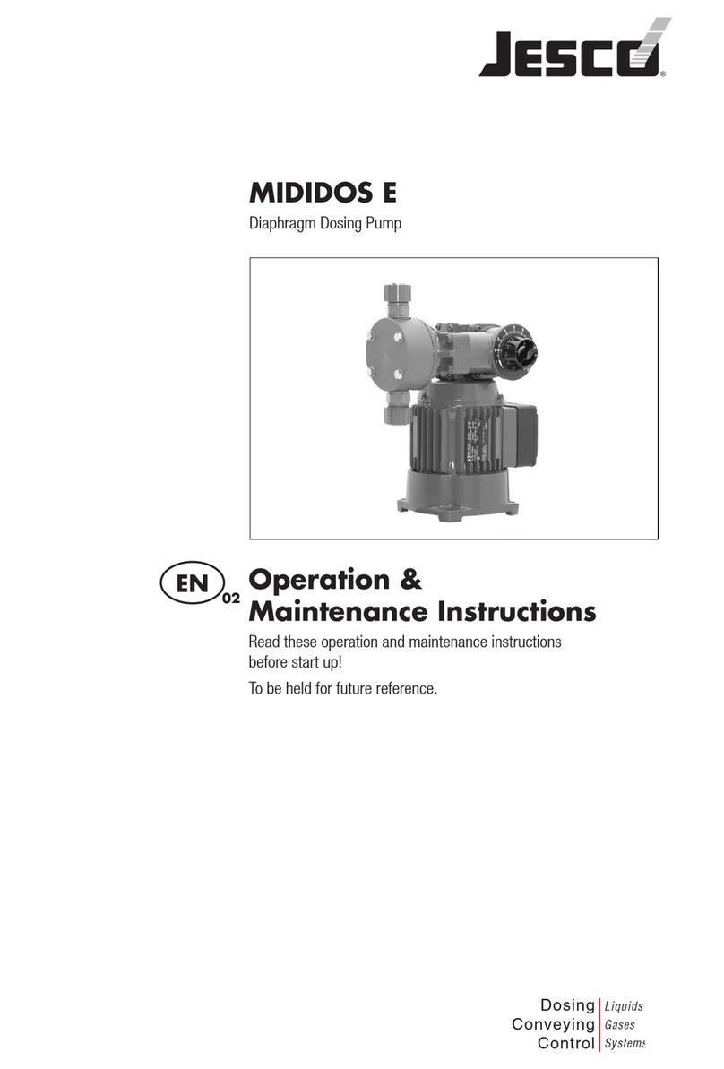
Jesco Peristaltic Pump 2.8 l/h Instruction Manual

Peristaltic Pump 2,8l/h
Operation &
Maintenance Instructions
Read these operation and maintenance instructions
before start up!
To be held for future reference.
Dosing
Conveying
Control
Liquids
Gases
Systems
EN 02

2 | Operation & Maintenance Instructions Peristaltic Pump | Content
Contents
1. Safety advice ....................................................................................................... 4
1.1 General.......................................................................................................... 4
1.2 Instruction symbols used in the operating manual ............................................ 4
1.3 Qualification and training of personnel ............................................................. 4
1.4 Important safety instructions ........................................................................... 5
1.5 Hazards due to non-compliance with safety instructions ................................... 5
1.6 Safe operation................................................................................................ 6
1.7 Safety instructions for the owner/operator........................................................ 6
1.8 Safety instructions for inspection-, maintenance- and installation work .............. 6
1.9 Unauthorised modifications and production of spare parts................................. 6
1.10 Impermissible modes of operation ................................................................. 6
1.11 Metering of chemicals .................................................................................. 6
1.12 Scope of delivery.......................................................................................... 7
2. Proper use............................................................................................................ 7
3. Function ............................................................................................................... 7
4. Technical Data ..................................................................................................... 8
5. List of chemical resistance ................................................................................. 9
6. Dimensional drawing......................................................................................... 10
7. Installation ......................................................................................................... 11
7.1 General information ...................................................................................... 11
7.2 Wall mounting .............................................................................................. 11
7.3 Mounting the control cabinet......................................................................... 12
7.4 Hydraulic Installation..................................................................................... 12
7.5 Electric connection of the pump .................................................................... 14
7.6 Installation example...................................................................................... 16
8. Start-up.............................................................................................................. 17
9. Shutdown ........................................................................................................... 18
10. Maintenance .................................................................................................... 18
10.1 Changing the hose ..................................................................................... 19
10.2 Changing the rotor...................................................................................... 20
11. Spare parts....................................................................................................... 21

Content | Operation & Maintenance Instructions Peristaltic Pump | 3
12. Troubleshooting ............................................................................................... 22
13. Declaration of conformity................................................................................ 23
14. Declaration of harmlessness........................................................................... 24
15. Warranty........................................................................................................... 25
16. Revision............................................................................................................ 26

4 | Operation & Maintenance Instructions Peristaltic Pump | Safety advice
1. Safety advice
1.1 General
This operating manual contains basic information to be adhered to during installation,
operation and maintenace. It is therefore essential that the fitter as well as the relevant
qualified staff/operator read the operating manual before installing and starting up. It must
be accessible at the dosing pump/system at all times.
Not only must the general safety instructions under this main heading of Safety be ob-
served, but also the specific safety instructions outlined under the other headings.
1.2 Instruction symbols used in the operating manual
If the safety instructions in this operating manual are not adhered to it may endanger
people, the environment and the dosing pump/system. These instructions are denoted by
the following symbols:
DANGER!
Refers to an imminent danger. Non-compliance can lead to death or serious injury.
WARNING!
Refers to a potentially dangerous situation. Non-compliance can lead to death or serious
injury.
CAUTION!
Refers to a potentially dangerous situation. Non-compliance can lead to minor injury or
damage to property.
NOTICE! or INFORMATION!
Are safety instructions which if ignored can lead to danger to the machine and its func-
tions.
IMPORTANT!
This is additional information to ensure that work is facilitated and a trouble-free operation.
There are marking affixed directly onto the pump, e.g.:
• specification label
• warning notices
that must be observed without fail and remain fully legible at all times.
1.3 Qualification and training of personnel
The personnel employed for the installation, opertaion, inspection and maintence work
must be qualified to do so. The user has to define precisley the areas of responsibility,
competence and supervision of the personnel. If the personnel do not have the necessary
knowledge, they must be trained and instructed. If necessary, the manufacturer/supplier

Safety advice | Operation & Maintenance Instructions Peristaltic Pump | 5
may do this on behalf of the pump’s owner. Furthermore, the owner of the system has to
ensure that the contents of this operating manual is fully understood by the personnel.
1.4 Important safety instructions
When installing and using this electrical equipment, basic safety precautions should
always be followed, including the following:
READ AND FOLLOW ALL INSTRUCTIONS!
WARNING!
To reduce the risk of injury, children are not permitted to use this product, they should be
closely supervised at all times.
WARNING!
Risk of electric shocks.
Connect the device only to a grounding receptacle that is secured by a ground-fault-
circuit-interrupter (GFCI). Contact a qualified electrician if you cannot verify that the
receptacle is protected by a GFCI.
Do not bury the cable. Fuse the cable in order to minimmise damage from lawn mowers,
hedge trimmers and other appliances.
WARNING!
To reduce the risk of an electric shock, replace a damaged cable immediately.
WARNING!
To reduce the risk of an electric shock, do not connect the unit to an extension cord with
electric voltage, use a suitably located socket instead.
DANGER!
Burn hazard.
Compressional wave: pieces flying out can kill you. The peristaltic pump must never be
used in an explosive area.
SAVE THESE INSTRUCTIONS!
1.5 Hazards due to non-compliance with safety instructions
Failure to comply with safety instructions may endanger not only people, but also the
environment and the dosing pump/system. Non-compliance with the safety instructions
can lead to the loss of all claims for damages. Non-compliance can lead to the following
hazards:
• Malfunction of the dosing pump/system’s important functions.
• Malfunction of prescribed methods of maintenance and servicing.
• Endangering people through electrical, mechanical and chemical causes.
• Endangering the environment due to leakages of hazardous substances.

6 | Operation & Maintenance Instructions Peristaltic Pump | Safety advice
1.6 Safe operation
The safety instructions in this operating manual have to be observed. The owner is respon-
sible for ensuring compliance with local safety regulations.
1.7 Safety instructions for the owner/operator
Leakages (e.g. due to ruptures in the hose) of hazardous materials conveyed (e.g. abrasive,
toxic) have to be discharged in such a way so that there is no danger to people and the
environment. Statutory regulations must be observed.
Hazards through electric currents have to be eliminated (for full details refer to the VDE
(German Electrical Engineering Association) regulations, for example, and the local Electric-
ity Board, as well as chapter 1.4)
1.8 Safety instructions for inspection-, maintenance- and installation work
The owner must ensure that all inspection, maintenance and installation work is under-
taken by authorised and duly qualified personnel who have also studied this operating
manual.
Work on the pump must be done strictly when it is at a complete stop. The procedure
specified in this operating manual for shutting down the dosing pump/system must be
observed without fail.
Peristaltic pumps or systems that convey harmful media have to be decontaminated before
work starts.
After work has finished all the safety mechanisms and guards have to be directly refitted
and/or reactivated.
The instructions outlined in chapters 7 and 8, under „Installtion“ and „Start up“ must be
observed before starting up.
1.9 Unauthorised modifications and production of spare parts
Modifications and alterations are only permitted after consulting with the manufacturer.
Genuine spare parts and accessories authorised by the manufacturer ensure security.
IMPORTANT!
The use of spare parts that are not genuine negates all claims for damages.
1.10 Impermissible modes of operation
All modes of operation that are not in line with those in chapter 2 „Proper Use“ are imper-
missible and consequently all claims for damages are forfeited.
1.11 Metering of chemicals
CAUTION!
When working on batchers the accident prevention regulations applicable on-site must
be observed and the prescribed personal protective clothing must be worn This operat-
ing manual contains basic information to be adhered to during installation, operation and
maintenace. It is therefore essential that the fitter as well as the relevant qualified staff/op-

Proper use | Function | Operation & Maintenance Instructions Peristaltic Pump | 7
erator read the operating manual before installing and starting up. It must be accessible at
the dosing pump/system at all times.
Not only must the general safety instructions under this main heading of Safety be ob-
served, but also the specific safety instructions outlined under the other headings.
1.12 Scope of delivery
IMPORTANT!
Please unpack the peristaltic pump and ordered accessories attached with great care, so
that small parts do not remain unnoticed in the packaging. Please compare the scope of
delivery immediately with the delivery note. The reason for any discrepancies has to be
ascertained.
2. Proper use
The proper use of the peristaltic pump is with the supply and metering of chemicals under
low pressure.
The appropriate operational conditions in chapter 4 „Technical data“ have to be main-
tained.
3. Function
The peristaltic pump is a positive displacement pump. The rotor’s pressure rolls squeeze
the pump’s hose together and when they roll on the hose they push the medium in the
hose in the direction of the pressure connection.
This functional principle is distinguished by its:
• simple function
• good suitability to media involving gas
The pressure rolls are spring loaded and can avoid possible deposits in the pump hose. As
a result the service life of the pump is increased for media with solid parts.
The delivery rate of the peristaltic pump is controlled by an on/off switch on the power
supply.

8 | Operation & Maintenance Instructions Peristaltic Pump | Technical Data
4. Technical Data
Delivery rate 2.8 l/h
Accuracy ±10% (with a new hose
max. manometric pressure 1.5 bar
max. capillary rise 300 mbar
No. of revolutions 30 /min
Voltage 230V 50Hz
Protection system IP 65
Power input max. 5 W
max. power-on time 100%
Environment temp. 5..40 °C
Media temp. 5..50 °C
Dimensions (WxHxD) 106x157x112mm
Weight ca. 750 g
Hydraulic connections for PE or PVC-hose 4/6mm
Electric supply 1.9 m power line with safety plug
Material in contact with media Pump hose NORPRENE®
NORPRENE® is a registered trademark of
Saint-Gobain Performance-Plastics.

List of chemical resistance | Operation & Maintenance Instructions Peristaltic Pump | 9
5. List of chemical resistance
The following list shows the hose pump’s chemical resistance against usual chemicals in
the water preparation.
Medium chem.
formula concentration. Performance
Aluminiumsalt all +
Calcium hypochlorite CaCl(ClO) 20% +
Ferrous salts all +
Common salt NaCl 20% +
Sodium hyperchlorite NaClO 12.5% +
Caustic soda NaOH 40% +
Hydrochloric acid HCl 10% +
37% 0
Sulphuric acid H2SO4 30% +
95% -
Hydrogen peroxide H2O2 30% +
90% 0
(+ / 0 / - none / minor/ stronger chemical attack)
The chemical resistance was determined at 20°C.
Please ask the supplier with regard to information on other chemicals or investigate them
through preliminary tests. For this purpose a section of hose is weighed and measured,
placed in the chemical for at least 24 hours, subsequently washed well and dried. The gain
in weight, change in size, moisture expansion and other changes such as brittleness and
discolouring are evaluated. If there is no clear change, then the pump hose can be used
for this chemical.

10 | Operation & Maintenance Instructions Peristaltic Pump | Dimensional drawing
6. Dimensional drawing
The peristaltic pump is delivered in a closed casing for wall mounting. Without a casing
bottom the pump can also be set up on level surfaces, e.g. switch/control cabinets.
66
106
157
38
89
112
79
80
61
4,5
O
70
Fig. 6.1: Dimensional drawing [mm]

Installation | Operation & Maintenance Instructions Peristaltic Pump | 11
7. Installation
7.1 General information
The choice of peristaltic pump when planning a system as well as the installation and the
operation, has to be done with due consideration of the local applicable regulations. This
applies to the choice of suitable materials, the handling of chemicals and the electrical
installation.
It is the planner’s and the owner’s responsibility to ensure that the entire system and the
pumps intergrated therein are designed in such a way that a chemical leak due to mal-
function of worn parts (e.g. pump hose) or ruptured hoses, does not lead to any sustain-
able damages to plant components and buildings. When there is a great risk of danger in
the chemical system, the installation has to be done in such a way that even if the pump
breaks down no disproportionately high consequential damages can arise. We therefore
recommend the installation of leakage monitors and collecting trays.
Operational reliability requires the use of appropriate accessories such as check valves
and injection points. Suitable tools always have to be used for the installation work of plas-
tic connection parts. In order to avoid corrosion you should only expend adequate power.
7.2 Wall mounting
The peristaltic pump has to be mounted higher than the maximum fluid level of the reserve
of the medium to be pumped in. The hose connections point downwards.
There is a wall holder with the delivery of the pump for wall mounting individual pumps. To
mount multiple pumps in a row, the following profile rails are available for delivery:
3-fold L=330mm Item-No. 38314
6-fold L=660mm Item-No. 38317
9-fold L=990mm Item-No. 38318
The wall holder has an asymmetrical profile.
The squared conture points upwards.
Tools are not required to mount the pump onto the wall holder. Connect on top first and
then press the pump on the bottom, until you hear it click in. To take the pump down, hold
on to the bottom of the pump casing and pull it from the wall.

12 | Operation & Maintenance Instructions Peristaltic Pump | Installation
7.3 Mounting the control cabinet
Without a casing bottom the peristaltic pump can also be mounted on to level surfaces like
control cabinets or other casings, for example.
!
95
85
110
70
10
3,4
O
20 x45°
Fig. 7.1: Front casing without casing bottom
When mounting make sure that there is a good sealing fit between the casing cover and
the wall. The support area has to be level, flat and compact enough, so that the sealing
strip can seal up well against the control cabinet
The fastening screws have to fit the thickness of the wall. The screws delivered with the
unit are suitable for a wall thickness of 3mm. The screw clamp is offset in the casing cover
at an upwards spacing .
WARNING!
Take care that the power supply line does not lie on the exhaust’s sharp edges and so be
damaged.
7.4 Hydraulic Installation
IMPORTANT!
When choosing the hose’s diameter and length take into consideration the total pressure
of the installation, which consists of the system pressure and all pressure drops in the
fittings and hoses. This total pressure may not exceed that indicated in the technical data
– chapter 4.

Installation | Operation & Maintenance Instructions Peristaltic Pump | 13
IMPORTANT!
If the pipes are laid badly vapour locks can amass in the dosing line, and they become
larger and smaller with variations in pressure. As a consequence the flow in the dosing line
can become intermittent. A check-valve on the peristaltic pump’s pressure socket rectifies
this.
CAUTION!
The pump head’s drainage connection has to be attached in such a way that leakages
from the pump head do not cause any damage. The hose should end, for example, in a
collecting tray with a leakage monitor. The discharge from the drainage hole must be pos-
sible on a free downward gradient.
90°
Fig. 7.2: Clamp connection
The process hose is fixed on to the pump with hose clamp connectors. The connection
consists of the integrated hose adaptor, a clamping ring and a coupling nut. The clamping
ring delivered with the unit is suitable for hoses made of PVC and PE. Harder hoses require
a different clamping ring (e.g. for PTFE item number: 88255)
• cut the hose end square
• slide the coupling nut and clamping ring on to the hose end (follow the direction of the
clamping ring)
• slide the hose end up to the stopper on the adaptor.
• slide the clamping ring on to the adaptor
• tighten the coupling nut by hand. (approx. 10 Ncm)
Suction pipe
In most installations there is a suction pipe with a check valve (=non-return valve), which
prevents flow back in worn out pump hoses, too.

14 | Operation & Maintenance Instructions Peristaltic Pump | Installation
Injection point
The injection points are there to intervene on the metered mediums in a main current and
also fufill the function of reversal at the same time. The injection piece is mostly mounted
from the top in the main line ① (see fig. 7.3). It is recommended to mount it from the bot-
tom if there are media which are subject to granulation, so that air locks cannot be sealed
inside ②.
①
②
Fig. 7.3: Injection point mounting positions
For media that are prone to contaminating the injection point, it is recommended to use
self-cleaning injection points. If necessary, injection points which can be dismantled and
sealed off for maintenance can be used.
IMPORTANT!
With peristaltic pumps, it is especially important to bear in mind that injection points use
low pressure drops, as the peristaltic pumps can in principle only build up low pressure
7.5 Electric connection of the pump
The electric connection of the peristaltic pump has to comply with the local regulations and
may only be carried out by qualified personnel.
CAUTION!
The peristaltic pump does not have an internal fuse. The fuse protection is to be under-
taken by the customer.

Installation | Operation & Maintenance Instructions Peristaltic Pump | 15
CAUTION!
Relays for the main voltage switch have to be protected from damages through demolish-
ing sparks, by a wireless quenching circuit.
The voltage supply is takes place via a power cable with a mains plug. A suitable socket
shall be provided for near to the pump.
The required degree of protection is guaranteed by the professional installation of the
electrical installation. Unused cable openings have to be sealed shut.
To avoid an unwanted metering after the end of the process an electrical locking mecha-
nism shall be provided for the pump.
The pump’s flow rate is proportioned by turning the power supply to the process on and
off. Normally a circuit is in the minute cycle and the switching frequency should not excede
10/min.
Fig. 7.4: 230V / 50 Hz power connection
Cable colours
bu: blue
bk: black
gnye: green-yellow
rd: red
ye: yellow

16 | Operation & Maintenance Instructions Peristaltic Pump | Installation
7.6 Installation example
1
2
3
4
5
6
7
Fig. 7.5: Installation example
Key:
①Collecting tray
②Chemical canister
③ Suction line with check valve
④Peristaltic pump
⑤Injection point with check valve
⑥Socket with fuse pin
⑦Drainage downpipe of the peristaltic pump

Start-up | Operation & Maintenance Instructions Peristaltic Pump | 17
8. Start-up
CAUTION!
When working on the peristaltic pump wear personal protective equipment in accordance
with the current accident prevention regulations!
Safety goggles Protective gloves Protective clothing
Before starting up the dosing pump all the tasks outlined in the section „Installation“
(chapter 7) have to be carried out. The safety instructions must be observed.
The peristaltic pump sucks in automatically and fills the pump hose during normal opera-
tion.
If the dosing process requires it at the beginning, the pump hose and hose lines have to be
filled with the chemicals before the system is started up. For this purpose switch to manual
operation and wait until all hose lines are filled. Afterwards switch the control back to the
regular operation.
When starting up, all the hose connections have to be checked for their impermeability
under operational pressure. If leakages are noticeable, turn off the pump and replace the
hose connection with a new one. If leakages are noticeable, turn the pump off and make a
new hose connection. Leaked chemicals have to be removed as per local regulations.
CAUTION!
Release the pressure in the line before opening the hose connection, as chemicals could
spray out.

18 | Operation & Maintenance Instructions Peristaltic Pump | Shutdown | Maintenance
9. Shutdown
Before maintenance work or longer-term service interruption empty the chemicals in the
peristaltic pump and flush it out with harmless mediums. (Water is often suitable).
CAUTION!
Surplus chemicals have to be disposed of professionally. When working on the peristaltic
pump wear the personal protective equipment in accordance with the current accident
prevention regulations!
Safety goggles Protective gloves Protective clothing
CAUTION!
Next, the pump has to be disconnected from the power supply and secured from resetting.
10. Maintenance
Peristaltic pumps are low maintenance pumps. Only the chemically and mechanically
highly loaded pump hose is subject to wear. Regular replacement of the hose protects
against interruptions in service!
If there should be a chemical attack on the rotor when the hose is ruptured, this can also
be exchanged.
If the pump is completely disjointed, the screws have to be tightened to the following
torque:
Casing screws: 20 Ncm
Pump head-fixing: 15 Ncm
CAUTION!
For all work carried out on the pump the power supply has to be disconnected and
secured against resetting.
CAUTION!
Release the pressure before opening the hose connections, so that chemicals cannot
spray out. The personal protective equipment in accordance with the current accident
prevention regulations have to be worn!
Safety goggles Protective gloves Protective clothing

Maintenance | Operation & Maintenance Instructions Peristaltic Pump | 19
10.1 Changing the hose
IMPORTANT!
The hose’s lifetime in continuous use amounts to approx. 1,000 hours. It is dependent on
the loading characterised by the medium, temperature, the suction level, pressure and how
often it is turned on. As the pump is not in continuous use in most applications, a yearly
hose replacement is often sufficient.
A worn hose loses its elasticity. Consequently, it has a lower capacity. A burst hose first
appears in the later stages of wear and tear.
Tools are not required to change the hose. The replacement hose is already mounted by
the factory on the hose carrier.
• Release pressure.
• Empty the pump of chemicals and flush it out with a harmless medium (water is often
suitable).
• Disconnect from the power supply and secure against resetting.
• Disconnect hose connections from the process hose.
• Dismantle the pump-head cap. If required a coin is helpful on the side notch on the
pump head. Care has to be taken so that the ball-bearing does not fall down.
• Place springs on the rotor in the right bracket.
• Turn the rotor clockwise with help from the spring and at the same time pull out the
hose carrier with the pump hose to the front.
Fig. 10.1: Opening pump-head for changing the hose
• Put the new pumps in, in reverse order. When assembling, the rotor has to be screwed
back on by hand. Make sure that the pump connection lies in the middle of the track.
• Place the ball-bearing in the cap.
• The pump head cap has to lock on to the pump head.
• Start up as per section 8.

20 | Operation & Maintenance Instructions Peristaltic Pump | Maintenance
10.2 Changing the rotor
The rotor is pushed up on to the gear motor’s shaft. After removing the pump hose it can
be dismantled with a pull on the tension spring.
When mounting, a new rotor shaft’s flat sections have to square up with the rotor.
!
Fig. 10.2: Removing the rotor#
Table of contents
Other Jesco Water Pump manuals

Jesco
Jesco C7520 User manual

Jesco
Jesco 43-20406 Instruction Manual

Jesco
Jesco MIDIDOS E Instruction Manual

Jesco
Jesco MAGDOS E User manual

Jesco
Jesco SD 5 00 01/1 User manual

Jesco
Jesco MAGDOS LT Instruction Manual

Jesco
Jesco MEMDOS E User manual

Jesco
Jesco MAGDOS DE/DX User manual

Jesco
Jesco Lutz PVC GF-2 User manual

Jesco
Jesco FEDOS E 5 User manual
Popular Water Pump manuals by other brands

Accudyne Industries
Accudyne Industries Milton Roy MILROYAL C Installation, operation & maintenance manual

CET
CET PFP-20HPHND-2D Instruction handbook

Pentair
Pentair NOCCHI SSH owner's manual

Aquatec
Aquatec AquaPRO HOTLINE 1300 instruction manual

SKC
SKC AirChek XR5000 operating instructions

Danfoss
Danfoss RSA 28 installation guide