Jesco MAGDOS LK User manual
Dosing
Conveying
Control
Liquids
Gases
Systems
Original Operating Instructions
© Lutz-Jesco GmbH 2015
BA-10221-02-V03
Stepper Motor-driven Diaphragm Dosing Pump
MAGDOS LK
Operating Instructions
Read the Operating Instructions!
The user is responsible for installation and operation related mistakes!


Contents 3
© Lutz-Jesco GmbH 2015
Subject to technical changes.
150225
BA-10221-02-V03
Stepper Motor-driven Diaphragm Dosing Pump MAGDOS LK Operating Instructions
Contents
1 Notes to the Reader............................................................4
1.1 General non-discrimination......................................................4
1.2 Explanation of signal words......................................................4
1.3 Explanation of warning signs....................................................4
1.4 Identification of warnings.........................................................4
1.5 Identification of instructions for action......................................5
2 Safety .................................................................................6
2.1 General warnings.....................................................................6
2.2 Hazards due to non-compliance with the safety instructions .....7
2.3 Safe operation .........................................................................7
2.4 Personal protective equipment.................................................7
2.5 Personnel qualification.............................................................7
3 Appropriate and intended use ...........................................8
3.1 Notes on product warranty.......................................................8
3.2 Intended purpose.....................................................................8
3.3 Device revision ........................................................................8
3.4 Principles ................................................................................8
3.5 Prohibited dosing media...........................................................8
3.6 Foreseeable misuse.................................................................8
4 Product Description .........................................................10
4.1 Properties..............................................................................10
4.2 Scope of delivery ...................................................................10
4.3 Structure of the dosing pump .................................................10
4.4 Function description ..............................................................11
4.5 Nameplate.............................................................................11
5 Technical Data..................................................................12
5.1 Delivery capacity data............................................................12
5.2 Operating conditions and limits ..............................................12
5.3 Electrical data........................................................................13
5.4 Other data .............................................................................13
6 Dimensions ......................................................................14
6.1 MAGDOS LK with dosing head made of PVC, PP or PVDF .........14
6.2 MAGDOS LK with dosing head made of stainless steel (1.4571)...
14
7 Installing the Dosing Pump..............................................15
7.1 Set up information .................................................................15
7.2 Installation examples .............................................................15
8 Hydraulic installation.......................................................16
8.1 Dimensioning of the system ...................................................16
8.2 System piping........................................................................17
8.3 Aligning the dosing head ........................................................17
8.4 Hydraulic connections............................................................17
8.5 Connecting a leakage drain....................................................19
8.6 Connecting the dosing head venting facility ............................19
8.7 Hydraulic accessories ............................................................20
9 Electrical installation.......................................................26
9.1 Principles ..............................................................................26
9.2 Description of connection sockets..........................................26
10 Control..............................................................................29
10.1 Operator controls of the control unit......................................29
10.2 Explanation of menu navigation............................................29
10.3 Explanation of the menu icons..............................................29
10.4 Menu settings at initial commissioning.................................30
10.5 Main menu ..........................................................................30
10.6 System setup.......................................................................30
10.7 Information about the dosing pump ......................................33
11 Operation..........................................................................34
11.1 Commissioning the dosing pump..........................................34
11.2 Operating modes .................................................................36
11.3 External On/Off via Release input..........................................39
11.4 Decommissioning the dosing pump......................................39
11.5 Shutting down in an emergency ...........................................40
11.6 Storage ...............................................................................40
11.7 Transportation......................................................................40
11.8 Disposal of old units.............................................................40
12 Maintenance ....................................................................41
12.1 Maintenance intervals..........................................................41
12.2 Tighten up dosing head bolts................................................42
12.3 Change the diaphragm.........................................................42
12.4 Clean suction and discharge valves......................................42
13 Troubleshooting ...............................................................43
13.1 Type of fault .........................................................................43
14 Spare parts.......................................................................46
14.1 Diaphragm spare parts kits ..................................................46
14.2 Dosing head spare parts kits including valves .......................46
15 Delivery characteristic curves.........................................47
16 Menu structure of the Control Unit ..................................48
16.1 Program start.......................................................................48
16.2 System setup.......................................................................48
16.3 Main menu ..........................................................................51
17 Appendix ..........................................................................53
17.1 Default settings....................................................................53
18 EC Declaration of Conformity...........................................54
19 Declaration of harmlessness...........................................55
20 Warranty application .......................................................56
Index ......................................................................................57
Notes to the Reader
General non-discrimination
4© Lutz-Jesco GmbH 2015
BA-10221-02-V03
Stepper Motor-driven Diaphragm Dosing Pump MAGDOS LK Operating Instructions
1 Notes to the Reader
These Operating instructions contain the information and rules of
behaviour necessary for safe and correct operation of the MAGDOS LK
dosing pump.
Follow these principles:
nRead the entire Operating instructions prior to commissioning the unit.
nEnsure that everyone who works with or on the dosing pump has read
the operating instructions and follows them.
nKeep the operating instructions for the entire service life of the dosing
pump.
nPass on the operating instructions to any subsequent owner of the
dosing pump.
1.1 General non-discrimination
In these operating instructions, only the male gender is used where
grammar allows gender allocation. The purpose of this is to make the text
easy to read. Men and women are always referred to equally. We would
like to ask female readers for understanding of this text simplification.
1.2 Explanation of signal words
Different signal words in combination with warning signs are used in
these Operating instructions. Signal words illustrate the gravity of
possible injuries if the risk is ignored:
Signal word Meaning
DANGER Refers to imminent danger. Ignoring this sign may
lead to death or the most serious injuries.
WARNING Refers to a potentially hazardous situation.
Ignoring this sign might lead to death or the most
serious injuries.
CAUTION Refers to a potentially hazardous situation.
Ignoring this sign may lead to light injuries or
damage to property.
NOTICE Refers to a danger which, if ignored, may
compromise the unit or its function.
Tab. 1: Explanations of signal words
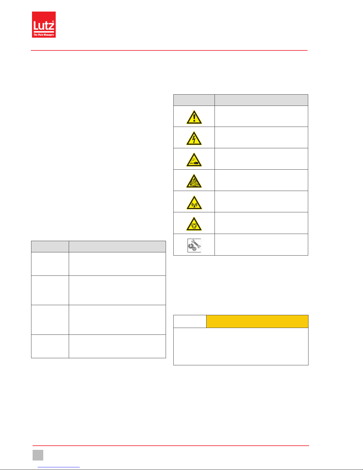
1.3 Explanation of warning signs
Warning signs represent the type and source of a danger:
Warning sign Type of danger
General danger zone
Danger of electric shock
Danger of caustic or other burns.
Danger of explosions
Danger of magnetic radiation
Danger of automatic start up
Danger of damage to machine or compromised
function.
Tab. 2: Explanations of warning signs
1.4 Identification of warnings
Warnings are intended to help you recognise risks and avoid negative
consequences.
This is how warnings are identified:
Warning sign SIGNAL WORD
Description of danger.
Consequences if ignored.
ðThe arrow signals a precautionary measure to be taken to
eliminate the danger.

Notes to the Reader
Identification of instructions for action 5
© Lutz-Jesco GmbH 2015
Subject to technical changes.
150225
BA-10221-02-V03
Stepper Motor-driven Diaphragm Dosing Pump MAGDOS LK Operating Instructions
1.5 Identification of instructions for action
This is how pre-conditions for action are identified:
üPre-condition for action which must be met before taking action.
This is how instructions for action are identified:
èSeparate step with no follow-up action.
1. First step in a series of steps.
2. Second step in a series of steps.
4Result of the above action.
üAction completed, aim achieved.

Safety
General warnings
6© Lutz-Jesco GmbH 2015
BA-10221-02-V03
Stepper Motor-driven Diaphragm Dosing Pump MAGDOS LK Operating Instructions
2 Safety
2.1 General warnings
The following warnings are intended to help you to eliminate the dangers
that can arise while handling the dosing pump. Risk prevention measures
always apply regardless of any specific action.
Safety instructions warning against risks arising from specific activities
or situations can be found in the respective sub-chapters.
DANGER
Danger to life due to electric shock!
Wrongly connected or located cables or damaged ones can injure you.
ðConnect the device only to a socket outlet with earthing contact
protected by a ground fault circuit interrupter (GFCI).
ðReplace damaged cables without delay.
ðDo not use extension cables.
ðDo not bury cables.
ðSecure cables to avoid being damaged by other equipment.
DANGER
Danger to life through explosions!
When using dosing pumps without ATEX certification in a potentially
explosive area, explosions can occur that result in fatal injuries.
ðNever use the MAGDOS LK dosing pump in potentially explosive
areas.
WARNING
Caustic burns or other burns through dosing media!
After connecting the mains supply, residual dosing media in the
dosing head can spray out.
ðBefore connecting the mains supply, connect the dosing lines.
ðCheck that all the screw connections have been tightened
correctly and are leak-proof.
WARNING
Caustic burns or other burns through dosing media!
While working on the dosing head, valves and connections, you may
come into contact with dosing media.
ðUse sufficient personal protective equipment.
ðRinse the dosing pump with a liquid (e.g. water) which does not
pose any risk. Ensure that the liquid is compatible with the dosing
medium.
ðRelease pressure in hydraulic parts.
ðNever look into open ends of plugged pipelines and valves.
WARNING
Caustic burns or other burns through dosing media!
The materials of the dosing pump and hydraulic parts of the system
must be suitable for the dosing medium that is used. Should this not
be the case, the dosing media may leak.
ðMake sure that the materials you are using are suitable for the
dosing medium.
ðMake sure that the lubricants, adhesives, sealants, etc. that you
use are suitable for the dosing medium.
WARNING
Danger due to magnetic radiation for people with
pacemakers!
During operation solenoid diaphragm dosing pumps emit a stray
magnetic field. If you do not keep far enough away, the function of a
pacemaker can be negatively affected.
ðPeople with pacemakers must always keep at least 50 cm away
from the dosing pump..
CAUTION
Increased risk of accidents due to insufficient qualifica-
tion of personnel!
Dosing pumps and their accessories may only be installed, operated
and maintained by personnel with sufficient qualifications. Insufficient
qualification will raise the risk of accidents.
ðEnsure that all action is taken only by personnel with sufficient and
corresponding qualifications.
ðPrevent access to the system for unauthorised persons.
Safety
Hazards due to non-compliance with the safety instructions 7
© Lutz-Jesco GmbH 2015
Subject to technical changes.
150225
BA-10221-02-V03
Stepper Motor-driven Diaphragm Dosing Pump MAGDOS LK Operating Instructions
CAUTION
Danger of personal injury and material damage!
Changing dosing media can lead to unpredictable reactions.
ðThoroughly clean the dosing pump and appropriate sections of
the plant to avoid chemical reactions.
2.2 Hazards due to non-compliance with the safety
instructions
Failure to observe the safety instructions can pose a risk not only to the
personnel, but consequentially to the environment and the unit.
The specific consequences can be:
nFailure of vital functions of the dosing pump and the system,
nfailure of required maintenance and repair methods,
ndanger for individuals through dangerous dosing media,
ndanger to the environment through substances leaking from the
system.
2.3 Safe operation
Besides the safety instructions specified in these Operating instructions,
further safety rules apply and must be followed:
nAccident prevention regulations,
nsafety and operating provisions,
nsafety provisions for handling dangerous substances (mostly the
safety data sheets to dosing media),
nenvironmental protection provisions,
napplicable standards and legislation.
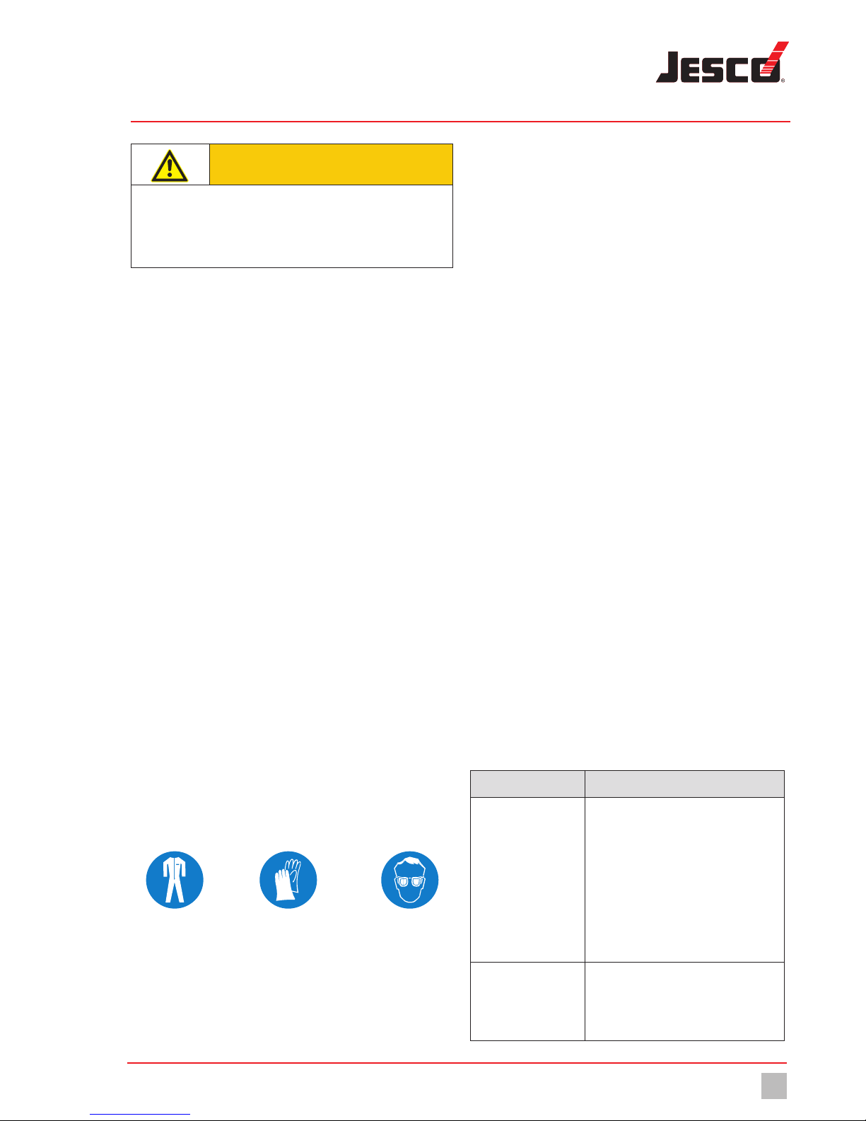
2.4 Personal protective equipment
Based on the degree of risk posed by the dosing medium and the type of
work you are carrying out, you must use corresponding protective
equipment. Read the Accident Prevention Regulations and the Safety
Data Sheets to the dosing media find out what protective equipment you
need.
As a minimum, the following protective equipment is recommended:
Protective clothing Protective gloves Goggles
Corresponding protective equipment must be used during these tasks:
nCommissioning,
nworking on the dosing pump while running,
ndecommissioning,
nmaintenance work,
ndisposal.
2.5 Personnel qualification
Any personnel who work on the dosing pump must have appropriate
special knowledge and skills.
Anybody who works with the dosing pump must meet the conditions
below:
nAttendance at all the training courses offered by the owner,
nPersonal suitability for the respective job,
nSufficient qualification for the respective job,
nTraining in handling of the dosing pump,
nKnowledge of safety equipment and the way this equipment
functions,
nKnowledge of these Operating instructions, particularly of safety
instructions and sections relevant for the job,
nKnowledge of fundamental regulations regarding health and safety
and accident prevention.
All persons must generally have the following minimum qualification:
nTraining as specialists to carry out work on the dosing pump
unsupervised,
nSufficient training that they can work on the dosing pump under the
supervision and guidance of a trained specialist.
These Operating instructions differentiate these user groups:
2.5.1 Expert staff
Expert staff are able, thanks to their professional training, knowledge and
experience as well as knowledge of the respective provisions, to do the
job allocated to them and recognise and/or eliminate any possible
dangers by themselves.
2.5.2 Trained persons
Trained persons have been trained by the operator into the tasks they are
supposed to perform and into the dangers stemming from improper
behaviour.
In the table below you can check what qualifications are the pre-condi-
tion for the respective tasks. Only people with appropriate qualifications
are allowed to perform these tasks!
Qualification Activities
Expert staff nAssembly
nHydraulic installations
nElectrical installations
nMaintenance
nRepairs
nCommissioning
nDecommissioning
nDisposal
nTroubleshooting
Trained persons nStorage
nTransportation
nControl
nTroubleshooting
Tab. 3: Personnel qualification

Appropriate and intended use
Notes on product warranty
8© Lutz-Jesco GmbH 2015
BA-10221-02-V03
Stepper Motor-driven Diaphragm Dosing Pump MAGDOS LK Operating Instructions
3 Appropriate and intended use
3.1 Notes on product warranty
Any non-designated use of the product can compromise its function or
intended protection. This leads to invalidation of any warranty claims!
Please note that liability is on the side of the user in the following cases:
nThe dosing pump is operated in a manner which is not consistent with
these Operating instructions, particularly the safety and handling
instructions and the chapter entitled „Appropriate and intended use“.
nIf people operate the product who are not adequately qualified to carry
out their respective activities,
nNo original spare parts or accessories of Lutz-Jesco GmbH are used,
nUnauthorised changes are made to the device by the user,
nThe user uses different dosing media than those indicated in the
order,
nThe user does not use dosing media under the conditions agreed with
the manufacturer such as modified concentration, density, tempera-
ture, contamination, etc.
3.2 Intended purpose
The MAGDOS LK dosing pump is intended for the following purpose: the
conveying and dosing of liquids.
3.3 Device revision
This operating manual applies to the following devices:
Device Month / year of
manufacture
Firmware
MAGDOS LK 03/2015 onwards 1.49 onwards
Tab. 4: Device revision
3.4 Principles
nBefore delivery, the manufacturer inspected the dosing pump and
operated it under specific conditions (with a specific dosing medium
with a specific density and temperature, with specific pipe dimen-
sions, etc.) Since these conditions vary at every installation location,
you must calibrate the dosing pump after delivery. For information on
the calibration procedure refer to “Calibrating the dosing pump“ (see
page35). For details on the approximate values and the capacity of
the dosing pump, refer to the chapter entitled “Delivery characteristic
curves“ (see page45).
nInformation on the usage and environment (see “Technical Data“ on
page12) applies.
nAny restrictions regarding the viscosity, temperature and density of
dosing media must be followed. You must only use dosing media at
temperatures above freezing point or below the boiling point of the
respective medium.
nThe materials of the dosing pump and hydraulic parts of the system
must be suitable for the dosing medium that is used. In this connec-
tion, note that the resistance of these components can change in
dependence on the temperature of the media and the operating
pressure.
i
Information on the suitability of materials combined with
different dosing media can be found in the Chemical
Resistance List of Lutz-Jesco GmbH.
The information in this resistance list is based on information
from the material manufacturers and on expertise obtained by
Lutz-Jesco from handling the materials.
As the durability of the materials depends on many factors,
this list only constitutes initial guidance on selecting material.
In all cases, test the equipment with the chemicals you use
under operating conditions.
nThe dosing pump is not intended for outdoor use unless appropriate
protective measures have been taken.
nAvoid leaks of liquids and dust into the casing and avoid direct
exposure to sunlight.
nYou must never operate dosing pumps in a potentially explosive
atmosphere if they do not have corresponding nameplates or an
appropriate EC Declaration of Conformity for potentially explosive
atmospheres.
3.5 Prohibited dosing media
The dosing pump must not be used for these media and substances:
nGaseous media,
nradioactive media,
nsolid substances,
ncombustible media,
nall other media that are not suitable for delivery using this dosing
pump.
3.6 Foreseeable misuse
Below, there is information about the applications of the dosing pump or
associated equipment that are not considered to be intended use. This
chapter is intended to allow you to detect possible misuse in advance and
to avoid it.
Foreseeable misuse is assigned to the individual stages of the product
lifetime:
3.6.1 Faulty assembly
nUnstable or unsuitable bracket
nDosing pump bolted wrongly or loosely
3.6.2 Faulty hydraulic installation
nSuction and pressure lines dimensioned incorrectly
nUnsuitable connection of the pipes due to wrong material or
unsuitable connections.
nSuction and pressure lines mixed-up
nDamage to threads due to them being tightened too much
nBending of pipelines
nNo free return flow of the pressure relief valve
nExcessive demand due to the pressure differences between the
suction and discharge valves

Appropriate and intended use
Foreseeable misuse 9
© Lutz-Jesco GmbH 2015
Subject to technical changes.
150225
BA-10221-02-V03
Stepper Motor-driven Diaphragm Dosing Pump MAGDOS LK Operating Instructions
nThrough-suction at installation without back-pressure valves
nDamage due to undamped acceleration mass forces
nExceeding the admissible pressure on the suction and discharge sides
nUsing damaged parts
3.6.3 Faulty electrical installation
nConnecting the mains voltage without a protective earth
nUnsecured mains or one that does not conform to standards
nNot possible to immediately or easily disconnect the power supply
nWrong connecting cables for mains voltage
nDosing pump accessories connected to wrong sockets
nProtective earth removed
3.6.4 Faulty commissioning
nCommissioning with damaged plant
nShut-off valves closed at commissioning
nClosed suction or pressure line, e.g. due to blockages
nPersonnel was not informed before commissioning
nSystem was recommissioned after maintenance without all the
protective equipment and fixtures, etc. being reconnected.
nInadequate protective clothing or none at all
3.6.5 Faulty operation
nProtective equipment not functioning correctly or dismantled
nModification of the dosing pump without authority
nIgnoring operational disturbances
nElimination of operational disturbances by personnel without
adequate qualifications
nDeposits in the dosing head due to inadequate purging, particularly
with suspensions
nBridging the external fuse
nOperation made more difficult due to inadequate lighting or machines
that are difficult to access
nOperation not possible due to dirty or illegible display of the dosing
pump
nDelivery of dosing media for which the system is not designed
nDelivery of particulate or contaminated dosing media
nInadequate protective clothing or none at all
3.6.6 Faulty maintenance
nCarrying out maintenance during ongoing operation
nCarrying out work that is not described in the operating instructions
nNo adequate or regular inspection of correct functioning
nNo replacement of damaged parts or cables with inadequate
insulation
nNo securing against reactivation during maintenance work
nUsing cleaning materials that can cause reactions with the dosing
media
nInadequate cleaning of the system
nUnsuitable purging medium
nUnsuitable cleaning materials
nCleaning materials left in system sections
nUsing unsuitable cleaning equipment
nUsing the wrong spares or lubricants
nContaminating the dosing medium with lubricant
nInstalling spares without following the instructions in the operating
manual
nBlocking venting orifices
nPulling off sections of the plant
nContamination at installation without a dirt trap
nMixing up the valves
nMixing up the sensor lines
nNot reconnecting all the lines
nDamaging or not installing all the seals
nNot renewing seals
nNot paying attention to safety data sheets
nInadequate protective clothing or none at all
3.6.7 Faulty decommissioning
nNot completely removing the dosing medium
nDismantling lines while the dosing pump is running
nDevice not disconnected from the power supply
nUsing the wrong dismantling tools
nInadequate protective clothing or none at all
3.6.8 Faulty disposal
nIncorrect disposal of dosing media, operating resources and other
materials
nNo labelling of hazardous substances

Product Description
Properties
10 © Lutz-Jesco GmbH 2015
BA-10221-02-V03
Stepper Motor-driven Diaphragm Dosing Pump MAGDOS LK Operating Instructions
4 Product Description
4.1 Properties
The MAGDOS LK is a Solenoid-Diaphragm Dosing Pump that is used
when precise dosing results are required.
They are characterized by the following properties:
nOutput range from 0.5 to 15 l/h, up to 16 bar,
nReproducible dosing precision of w 2%,
nIntegrated automatic dosing head venting facility (except with
stainless steel (1.4571) dosing heads),
nSuitable for highly aggressive or poisonous dosing media,
nOperating modes: Manual mode and Pulse input,
nGraphic display: 128 x 64 px, 1.5“, monochrome, illuminated,
nMenu languages: English, German, French, Spanish, Portuguese,
Dutch,
nFour multifunction keys for operator inputs,
nFloor- and wall-mounting options,
nRelease code and security code,
nCalibration option,
nEco-Mode energy-saving mode,
nConnections: M12x1 connector, A-coded
4.2 Scope of delivery
Please compare the delivery note with the scope of delivery. The
following items are part of the scope of delivery:
nMAGDOS LK dosing pump,
nOne set each of hose clamping connections for the suction and
discharge sides for hoses with diameters of 4/6 mm, 6/9 mm and
6/12 mm (made of PVC, PP and PVDF),
n3 covering caps for electrical connections (mounted on the dosing
pump),
nMains cable,
nOperating Manual,
nInspection report and test certificate (optional),
nAccessory kit (optional).
4.3 Structure of the dosing pump
4.3.1 General Overview
a
b
c
Fig. 1: Overview of MAGDOS LK dosing pump
No. Description
aDosing head
bDrive unit
cControl unit
4.3.2 Dosing head
a
c
d
b
Fig. 2: Dosing head
No. Description
aValve and connection on the discharge side
bintegrated dosing head venting facility (plastic version only)
cArrow indicating the direction of throughflow of the dosing
medium (plastic version only)
dValve and connection on the suction side

Product Description
Function description 11
© Lutz-Jesco GmbH 2015
Subject to technical changes.
150225
BA-10221-02-V03
Stepper Motor-driven Diaphragm Dosing Pump MAGDOS LK Operating Instructions
4.3.3 Control elements
a
b
d
c
Fig. 3: Controller of MAGDOS LK dosing pump
No. Description
aGraphic display
bMultifunction keys on the contol unit for operator inputs
cConnection sockets for external operation or connecting
accessories
dMains cable for power supply
Tab. 5: Designation of components
4.4 Function description
Dosing pumps are positive displacement pumps. They are used if
precisely defined delivery of a medium is necessary. A constant volume
per stroke or time is delivered.
The system delivers or meters the dosing medium by means of a
repeated sequence of suction strokes followed by pressure strokes. This
results in a pulsing flow.
If the dosing pump is in the suction stroke phase, the diaphragm is pulled
into the rear final position. Due to the resulting vacuum in the dosing
head, the discharge valve closes, the suction valve opens and dosing
medium flows from the suction line into the dosing head.
If the dosing pump is in the pressure stroke phase, the diaphragm is
moved into the front final position. Due to the pressure in the dosing head,
the suction valve closes and the dosing medium flows through the
discharge valve from the dosing head into the pressurised pipe.
4.5 Nameplate
There is information on the equipment about safety or the product‘s way
of functioning. The information must stay legible for the duration of the
service life of the product.
Fig. 4:
Material:
Max. XXX l/h at bar
Max. XXX l/h at bar
IP XX, XXX V, XXXX Hz, XX W
Lutz-Jesco GmbH
30900 Wedemark Germany
XX/XXXX
S/N: XXXXXXXXXXP/N:
Made in Germany
*102A12345678*
*12345678012345*
MAGDOS LK
a
b
c
d
e
MAGDOS LK nameplate
No. Description
aProduct, type, nominal size
bPart number
cType of material of dosing head/ type of material of seals
dMaximum delivery capacity at average pressure
eMaximum delivery capacity at maximum pressure
fProtection class
gVoltage supply
hFrequency
iPower consumption
jWEEE label
kLabel showing conformity with applicable European directives
lMonth / year of manufacture
mSerial number
Tab. 6: Nameplate
f g h i
j
k
l
m
Technical Data
Delivery capacity data
12 © Lutz-Jesco GmbH 2015
BA-10221-02-V03
Stepper Motor-driven Diaphragm Dosing Pump MAGDOS LK Operating Instructions
5 Technical Data
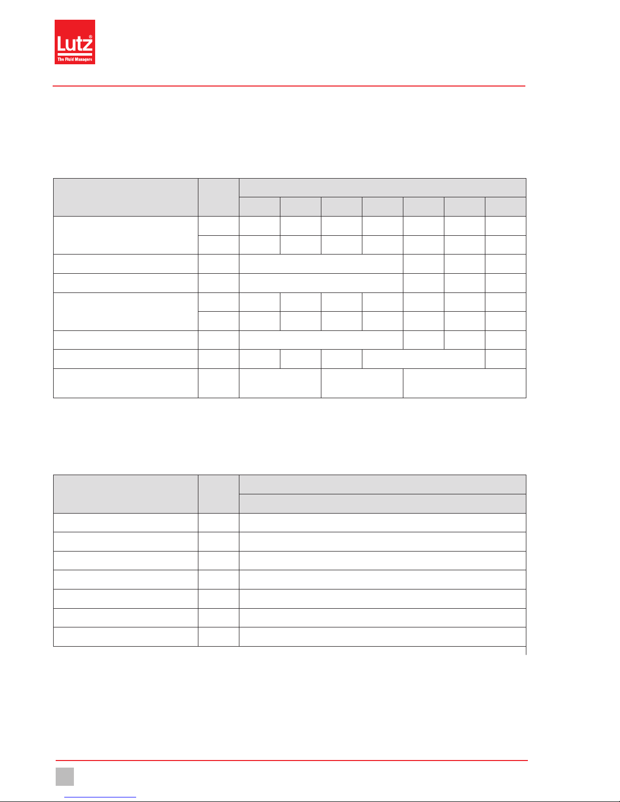
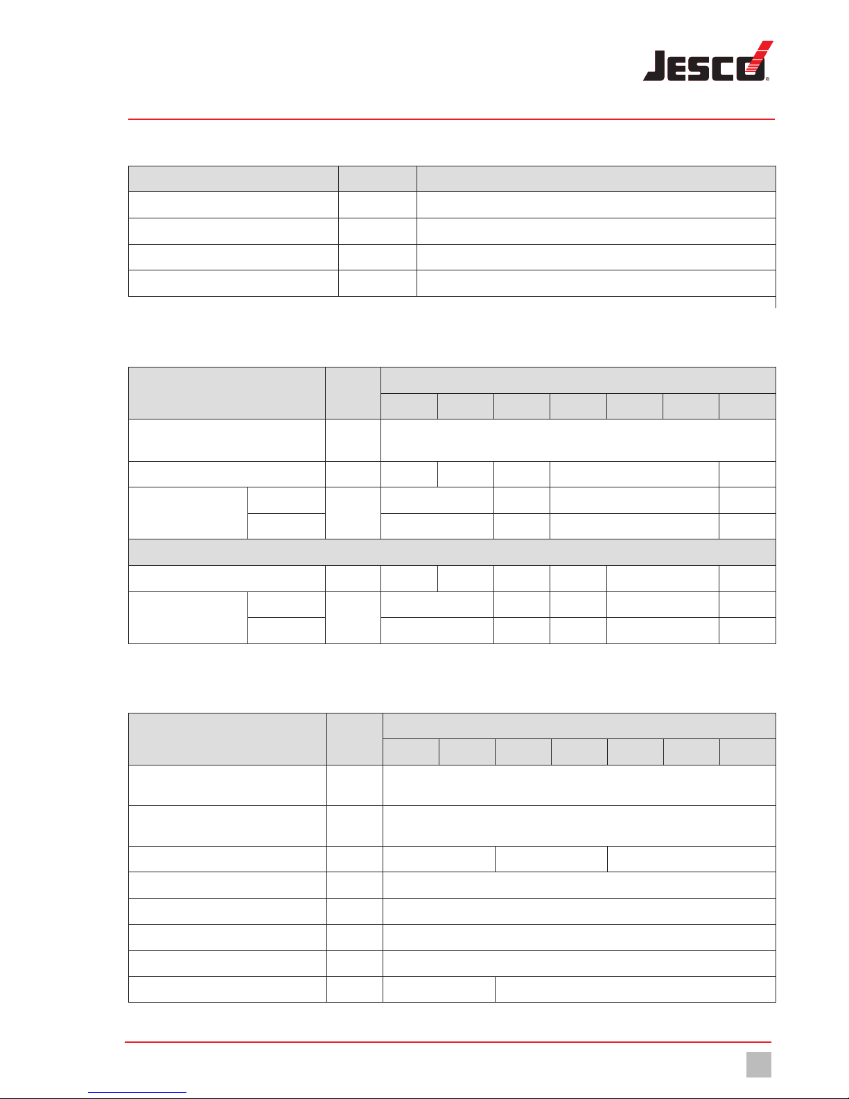
5.1 Delivery capacity data
Please note that some of this data only represents guide values. The actual capacity of a dosing pump depends on various factors. For approximate
values of the delivery capacity at different pressures, refer to “Delivery characteristic curves“ (see page45).
Information Value
MAGDOS LK size
05 1 2 4 6 10 15
Delivery capacity at max. back pressure
l/h 0.36 0.76 1.9 3.4 6.2 9.0 13
ml/stroke 0.05 0.05 0.2 0.32 0.57 0.83 0.87
Max. back pressure bar 16 8 6 3
Max. delivery pressure in Eco-Mode 1* bar 10 6 4 2
Delivery capacity at average back pressure
l/h 0.54 1.1 2.3 3.8 6.8 10 15
ml/stroke 0.08 0.08 0.24 0.35 0.63 0.92 1
Average back pressure bar 8 4 3 1
Max. stroke frequency RPM 120 250 160 180 250
Suction head for non-gassing media
(suction line filled) mWS 5 3 2
Tab. 7: Output data
* In the case of operation in Eco-Mode energy saving mode, the delivery capacity is 5-10 % less than in normal mode (with the same back pressure).
If necessary, recalibration may be necessary (see “Calibrating the dosing pump“ on page 35).
5.2 Operating conditions and limits
Information Value
MAGDOS LK size
05 – 15
Permitted ambient temperature °C 0 – 45 (0 – 40 with PVC parts)*
Relative humidity %Max. 90
Max. sound pressure level (depressurised) dB(A) 68 – 75
Max. sound pressure level (at test pressure) dB(A) 65 – 70
Max. supply pressure mbar 800
Viscosity limits mPas 300** / 1000***
Adjustable dosing range %0 – 100
Tab. 8: Operating conditions and limits
* Use of dosing pumps at ambient temperatures of under 5 °C has to be checked individually. In those cases please contact the manufacturer.
** With a viscosity of ~300 mPas and above, you must use spring-loaded valves.
*** If the viscosity is above 1000 mPas, this must be checked individually and the stroke frequency must be between 50 and 100 strokes/min.
Technical Data
Electrical data 13
© Lutz-Jesco GmbH 2015
Subject to technical changes.
150225
BA-10221-02-V03
Stepper Motor-driven Diaphragm Dosing Pump MAGDOS LK Operating Instructions
5.2.1 Permitted temperature of the medium
Information Value MAGDOS LK (all sizes)
Dosing head made of PVC °C 0 – 35
Dosing head made of PP °C 0 – 60
Dosing head made of PVDF °C 0 – 80
Dosing head made of stainless steel (1.4571) °C 0 – 80
Tab. 9: Permitted temperature of the medium
5.3 Electrical data
Information Value
MAGDOS LK size
05 1 2 4 6 10 15
Voltage supply 230 V AC ± 10 %, 50/60 Hz or
115 V AC ± 10 %, 50/60 Hz (refer to name plate)
Power consumption W 8 13 19 25 22
Max. current consump-
tion during dosing stroke
at 115 V AC
A
1,8 2,3 2,5 2,3
at 230 V AC 0,9 1,1 1,4 1,2
Eco-Mode 1
Power consumption W 6 9 14 16 18 17
Max. current consump-
tion during dosing stroke
at 115 V AC
A
1,6 1,9 2,2 2,3 2,0
at 230 V AC 0,8 0,9 1,0 1,1 0,9
Tab. 10: Electrical data
5.4 Other data
Information Value
MAGDOS LK size
05 1 2 4 6 10 15
Weight (with dosing head made of PVC, PP
or PVDF)
kg ~ 3.2
Weight (with dosing head made of stainless
steel (1.4571))
kg ~ 4.3
Diameter of diaphragm mm 24 33 39
Electrical cable m1.8 m (with mains plug)
Protection class IP65 (with covering caps on the connections)
Insulation class F
Valve connection G 5/8 external
Valve size DN3 DN4
Tab. 11: Other data
Dimensions
MAGDOS LK with dosing head made of PVC, PP or PVDF
14 © Lutz-Jesco GmbH 2015
BA-10221-02-V03
Stepper Motor-driven Diaphragm Dosing Pump MAGDOS LK Operating Instructions
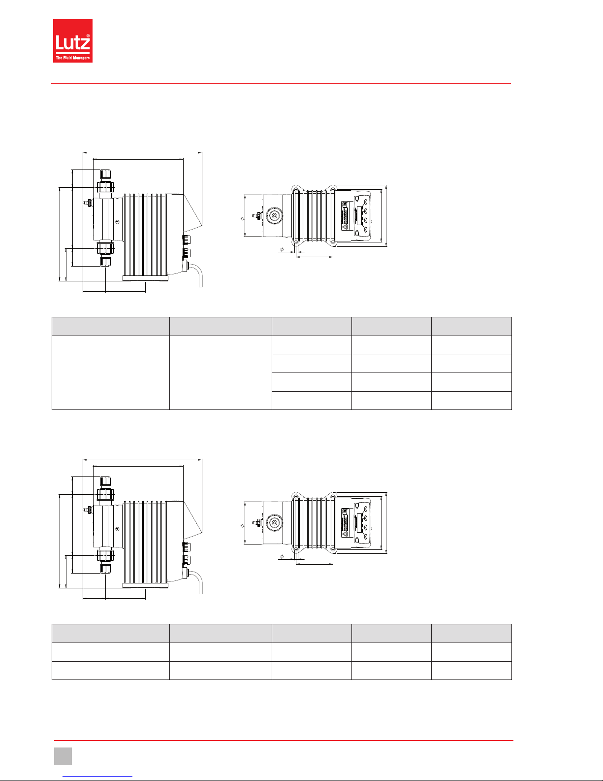
6 Dimensions
6.1 MAGDOS LK with dosing head made of PVC, PP or PVDF
Fig. 5: Dimensioned drawing of MAGDOS LK with dosing head made of PVC, PP or PVDF (all dimensions in mm)
Connection Material Size Nominal diameter L
Hose clip PVC / PP / PVDF
4/6 mm DN4 31
1/4x3/8” 1/4“ 34
6/9 mm DN6 34
6/12 mm DN6 15
6.2 MAGDOS LK with dosing head made of stainless steel (1.4571)
Fig. 6: Dimensioned drawing of MAGDOS LK with dosing head made of stainless steel (1.4571) (all dimensions in mm)
Connection Material Size Nominal diameter L
Hose clip Stainless steel (1.4571) / PVDF 4/6 mm DN4 50
Hose clip Stainless steel (1.4571) / PVDF 6/9 mm DN6 54
Installing the Dosing Pump
Set up information 15
© Lutz-Jesco GmbH 2015
Subject to technical changes.
150225
BA-10221-02-V03
Stepper Motor-driven Diaphragm Dosing Pump MAGDOS LK Operating Instructions
7 Installing the Dosing Pump
DANGER
Danger to life due to electric shock!
Electrically conductive liquid can enter pump housings, cable screw
connections and mains connectors.
ðMake sure that all protective measures comply at least with the
requirements of protection class IP65.
ðAlways set up the dosing pump such that water cannot enter the
housing.
CAUTION
Danger of personal injury and material damage!
A dosing pump that is difficult to access represents a danger due to
incorrect operation and faulty maintenance.
ðInstall the dosing pump such that it is accessible at all times.
7.1 Set up information
When installing, follow the basic principles below:
nThe valves must be vertical: Discharge valve at top, suction valve at
bottom. in this connection, pay attention to the arrow on the dosing
head. The dosing head must be aligned such that the arrow points
vertically upwards.
nYou should install the dosing pump at a convenient height for
operation.
nIt must not be installed under the ceiling.
nThe frame of foundation for fixing the dosing pump must not be
subjected to jolts. The pump must be vibration-free and stable.
nThere must be enough free space in the area of the dosing head and
the suction and discharge valves for these parts to be easily
dismantled if required. The entire space requirement for installation
and maintenance is approximately 1 m².
nThe distance from the sides of the dosing pump to the wall or other
dosing pumps or equipment must be at least 3 cm. There must be a
guaranteed flow of circulating air.
nThe maximum ambient temperature must be complied with, see
“Operating conditions and limits” on page12. If necessary, radiated
heat from surrounding equipment must be screened.
nAvoid exposure to direct sunlight.
nThe dosing pump is not intended for use out of doors unless
appropriate protective measures have been taken to prevent dust and
water from entering the housing.
nFor the dimensions of the fastening holes, refer to “Dimensions“ (see
page14).
nThe tightening torque for the fastening bolts is 1.5 - 2 Nm.
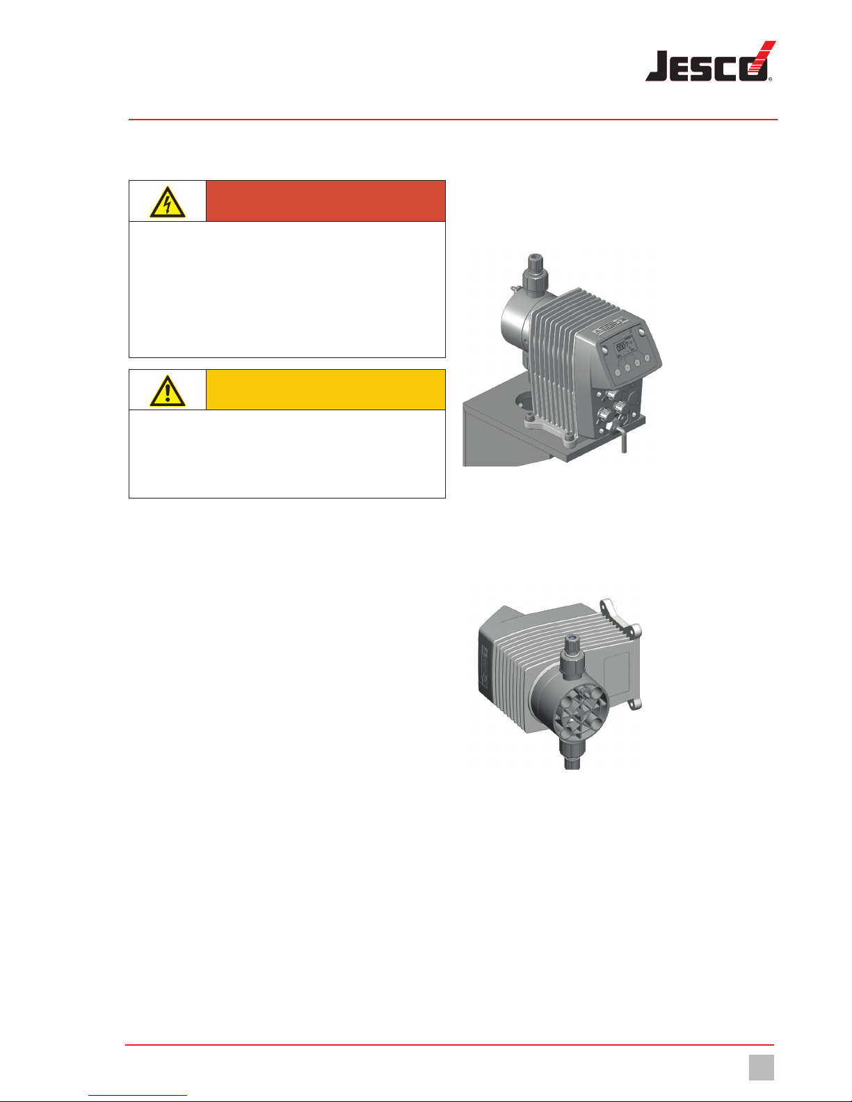
7.2 Installation examples
7.2.1 Installation on a wall bracket
Fig. 7: Installation on a wall bracket
To reduce the structure-borne noise, the dosing pump is bolted to the wall
bracket using rubber elements. The materials necessary for this are
included with the wall bracket.
7.2.2 Installation on the wall
Fig. 8: Installation on the wall
The dosing pump can be mounted to the floor or directly to the wall
without the need for additional elements. Turn the dosing head appro-
priately to ensure the flow direction of the medium through the dosing
head.

Hydraulic installation
Dimensioning of the system
16 © Lutz-Jesco GmbH 2015
BA-10221-02-V03
Stepper Motor-driven Diaphragm Dosing Pump MAGDOS LK Operating Instructions
8 Hydraulic installation
In this chapter, you will find information about the hydraulic parts of a
system that you should install or that can install additionally. In many
cases, you must install hydraulic accessories to be able to use all the
functions that the dosing pump MAGDOS LK offers, to guarantee
functional safety or to achieve a high level of dosing precision.
WARNING
Caustic burns or other burns through dosing media!
The materials of the dosing pump and hydraulic parts of the system
must be suitable for the dosing medium that is used. Should this not
be the case, the dosing media may leak. Depending on the type and
hazardousness of the dosing medium, this can result in injury.
ðMake sure that the materials you are using are suitable for the
dosing medium.
ðMake sure that the lubricants, adhesives, sealants, etc. that you
use are suitable for the dosing medium.
WARNING
Caustic burns or other burns through dosing media!
If there is a diaphragm rupture, the dosing medium can escape in an
uncontrolled way. Depending on the type and hazardousness of the
dosing medium, this can result in injury.
ðInstall a leakage drain.
WARNING
Caustic burns or other burns through dosing media!
The dosing pump can generate a pressure that is many times the
rated one. A blocked pressure line can lead to dosing medium
escaping. Depending on the type and hazardousness of the dosing
medium, this can result in injury.
ðInstall pressure relief valves.
CAUTION
Danger of personal injury and material damage!
High peak pressures can lead to piping vibrating and cause them to
snap. This can result in injury due to uncontrollable piping or escaping
dosing media.
ðInstall pulsation dampeners.
NOTICE
Damage to drives due to overloading
The pressure conditions between the suction and discharge sides
must be balanced; otherwise, overloading can result. This can lead to
uncontrolled dosing processes, damage to the plant pipework and to
the dosing pump.
ðEnsure that the pressure on the discharge side is at least 1 bar
greater than on the suction side.
NOTICE
Locking of threads
Stainless steel and plastic parts (particularly those made of PVC) that
are bolted together in a detachable connection (e.g. the dosing head
and the valves) can lock. This makes them difficult to release.
ðBefore bolting, grease the corresponding parts with a lubricant
(e.g. PTFE spray). Ensure that the lubricant is compatible with the
dosing medium.
8.1 Dimensioning of the system
nThe dosing pump’s technical data (see “Technical Data“ on page12)
must be taken into account and the plant’s layout must be set up
appropriately (e.g. pressure loss when rating the lines with regard to
their nominal diameter and length).
nYou must design the entire plant and its integrated dosing pump such
that escaping dosing medium due to the failure of wearing parts such
as the diaphragm, or to burst hoses does not lead to permanent
damage to parts of the system or the premises.
nThe leakage opening of the dosing head must be visible so that you
can detect a diaphragm failure. It must be possible for the outflow
from the leakage drain to be on a free downwards gradient.
nIf you use hazardous dosing media, the installation must be designed
such that no disproportionately high consequential damages arise
due to dosing media escaping.
nTo avoid dosing errors after the end of the process, the dosing pump
must be locked hydraulically.
nTo allow you to easily inspect the pressure conditions in the system,
you should provide connections for pressure gauges close to the
suction and discharge valves.
Hydraulic installation
System piping 17
© Lutz-Jesco GmbH 2015
Subject to technical changes.
150225
BA-10221-02-V03
Stepper Motor-driven Diaphragm Dosing Pump MAGDOS LK Operating Instructions
8.2 System piping
nThe system piping must not exert any force on the connections and
valves of the dosing pump.
nThis means that steel piping should be connected to the dosing pump
by means of flexible pipe sections.
nThe nominal diameters of the pipework and the installed fittings
should be rated the same as or greater than the nominal diameters of
the dosing pump‘s suction and discharge valves.
nThe suction line should be kept as short as possible.
nYou should avoid intertwined hoses.
nAvoid loops, since air bubbles can collect.
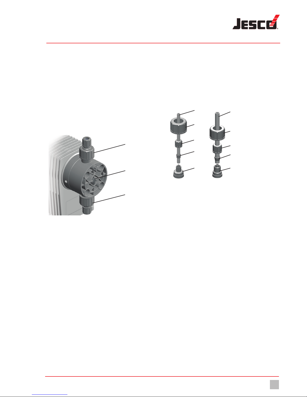
8.3 Aligning the dosing head
a
b
c
Fig. 9: Aligning the dosing head
When connecting the dosing lines to the dosing pump, you must observe
the direction of through-flow (see arrow b).The dosing head must be
aligned vertically.
The suction valve cmust always point downwards. Accordingly, arrow
band pressure valve falways point upwards. This is irrespective of
the positioning of the dosing head to the drive.
8.4 Hydraulic connections
8.4.1 Connecting hose clips
Choose the hose connection according to the condition of the hose
(material, inner diameter, wall thickness) in order to ensure maximum
pressure resistance.
8.4.1.1 Sizes 4/6 and 6/9
a
b
c
d
e
a
b
c
d
e
4/6 6/9
Fig. 10: Hose clips 4/6 and 6/9 (internal and external diameters in mm)
Perform the following working steps:
1. Cut the hose a to length neatly and at an exact right angle.
2. Place a gasket that is suitable for the dosing medium between the
connection e and the valve.
3. Screw the connecting piece eto the dosing pump‘s valve using the
union nut b.
4. Thread the union nut cand the clamping ring donto the hose.
5. Plug the hose aall the way in to the grommet of connection piece
e.
6. Push the clamping ring d onto the grommet of connection piecee
and screw it to the union nut c.
7. Carry out the same procedure with the connection to the dosing
pump‘s other valve.
üHose clip connected.
Hydraulic installation
Hydraulic connections
18 © Lutz-Jesco GmbH 2015
BA-10221-02-V03
Stepper Motor-driven Diaphragm Dosing Pump MAGDOS LK Operating Instructions
8.4.1.2 Size 6/12
a
b
c
d
Fig. 11: Hose clip 6/12 (internal and external diameter in mm)
Size 6/12 hose clips only have a union nut. It clamps the hose onto the
grommet of the connection piece and at the same time fastens on the
dosing pump‘s valve.
Perform the following working steps:
1. Cut the hose a to length neatly and at an exact right angle.
2. Place a gasket that is suitable for the dosing medium between the
connection d and the valve.
3. Push the union nut band the cutting ring cover the hose a.
4. Press the end of the hose aonto the grommet of connection
pieced.You can do this more easily by moistening the end of the
hose on the inside or applying some lubricant to the grommet in the
cone area. You should push at least two thirds of the hose onto the
grommet of the connection piece.
5. Push the cutting ring cover the hose ainto the cone area on the
grommet of connection piece d.
6. Screw the union nut bonto the valve of the dosing pump.
üHose clip connected.
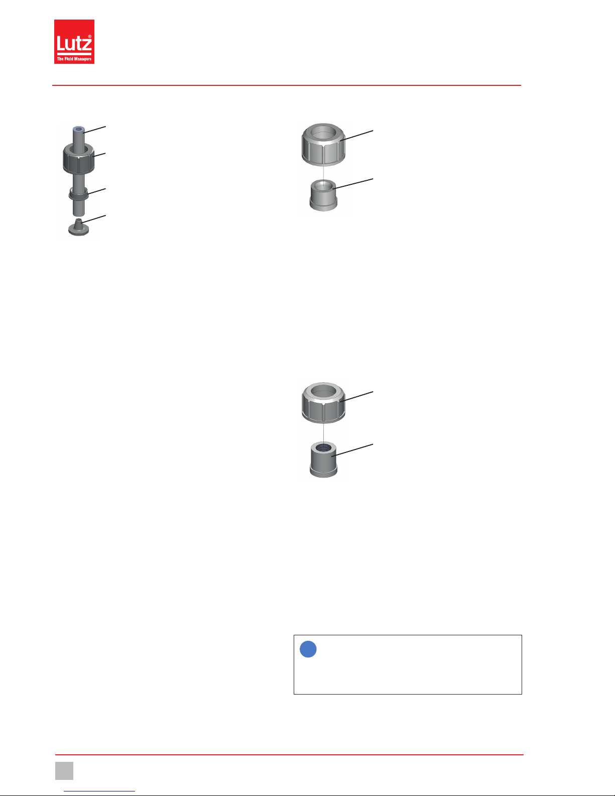
8.4.2 Making the bonded connection
a
b
Fig. 12: Bonded connection
Perform the following working steps:
1. Cut the PVC tube to length.
2. Push the union nut a onto the tube.
3. Stick the bonded coupling sleeve b to the tube (follow the
instructions of the adhesive manufacturer).
4. Screw the union nut a onto the valve of the dosing pump. Use a
gasket that is suitable for the dosing medium.
üBonded connection made.
8.4.3 Making the cemented connection
a
b
Fig. 13: Cemented connection
Perform the following working steps:
1. Cut the tube to length.
2. Cut the thread b onto the end of the tube.
3. Push the union nut a onto the tube.
4. Seal the thread b. When choosing your sealing material, take into
account its resistance to material, temperature and pressure.
5. Screw the union nut a onto the valve of the dosing pump. Use a
gasket that is suitable for the dosing medium.
üCemented connection made.
i
Under normal conditions, you only need to screw the hydraulic
connections finger-tight. However, due to the material settling,
the pre-tension of the screw connection can slacken. This
means that you must re-tighten the screw connection before
carrying out commissioning.
Hydraulic installation
Connecting a leakage drain 19
© Lutz-Jesco GmbH 2015
Subject to technical changes.
150225
BA-10221-02-V03
Stepper Motor-driven Diaphragm Dosing Pump MAGDOS LK Operating Instructions
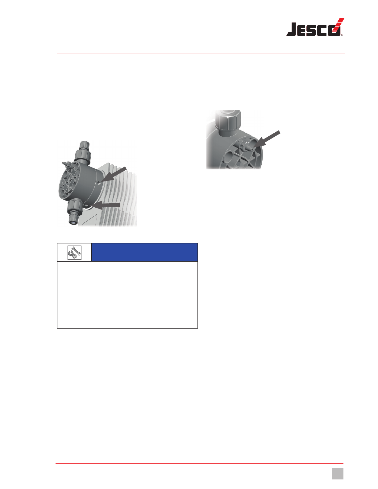
8.5 Connecting a leakage drain
Lutz-Jesco GmbH dosing pumps are produced to the highest quality
standards and have a long service life. However, some parts are subject
to operational wear. This is the case particularly with the diaphragms that
are continuously subjected to forces during the suction and discharge
strokes and to the effects of the dosing medium.
If a diaphragm ruptures, the dosing medium starts to leak.This leakage is
drained via the leakage opening. On the flange of the dosing head, there
are three openings for this purpose. Depending on the alignment of the
dosing pump, the leakage is drained via the downward opening.
Fig. 14: Openings of the leakage drain
NOTICE
Damage to drives due to effervescent media
If a hose is connected to the leakage drain and it is routed back into
the dosing tank, effervescent media can enter the drive and damage
it.
ðCollect the leakage in a collecting pan.
ðAs an alternative, you can route the leakage back to to the dosing
tank using a funnel. You should install the funnel at an adequate
distance from the leakage opening.
8.6 Connecting the dosing head venting facility
The MAGDOS LK dosing heads have an integrated dosing head venting
facility (except for dosing heads made of stainless steel).
For the procedure when venting, refer to “Venting the dosing pump” on
page34.
Fig. 15: Dosing head venting facility with hose connection
Perform the following working steps:
1. Connect a 4/6 hose to the dosing head venting facility.
2. Route the other end of the hose into the dosing tank or a collecting
tank.
üDosing head venting facility connected.
Hydraulic installation
Hydraulic accessories
20 © Lutz-Jesco GmbH 2015
BA-10221-02-V03
Stepper Motor-driven Diaphragm Dosing Pump MAGDOS LK Operating Instructions
8.7 Hydraulic accessories
The following chapter is intended to give you an overview of installation
options.
Please note that these operating instructions are no substitute for the
instructions supplied with the accessories in each case. The corre-
sponding documentation supplied with the product applies to safety
information and provides exact instructions on assembly.
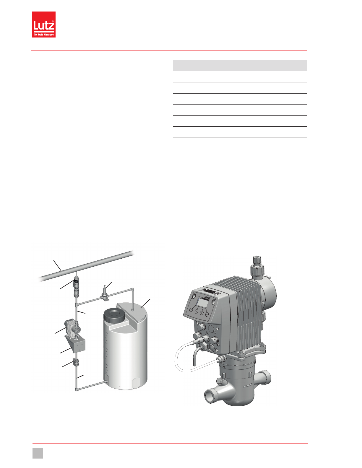
8.7.1 Injection nozzle
If the pressure line enters a main line, it is advisable to install an injection
nozzle.
Injection nozzles have three main functions:
nDosing the medium into a main line,
nPreventing flowback into the pressure line through a non-return valve.
Notes on assembly:
nDouble-ball injection nozzles must be installed into the main line
vertically from the bottom. You can install hose and spring-loaded
injection nozzles any way you like.
nWith dosing media that tend to crystallize, it is advisable to carry out
installation into the main line from the bottom. This prevents air
bubbles from being trapped.
nMany dosing media tend to contaminate the injection nozzles, which
can lead to blockages. In cases like this, it is advisable to install an
injection nozzle that is easy to dismantle and block off.
a
b
c
f
e
hi
d
g
Fig. 16: Installation with an injection nozzle
No. Description
aMain line
bInjection nozzle with shut-off valve
cPressure relief valve
dChemical tank
ePressure line
fMAGDOS LK dosing pump
gWall bracket
hShutoff valve
iSuction line
Tab. 12: Designation of components
8.7.2 Contact Water Meter
The contact-type water meter measures the throughflow in a pipe and
sends a pulse to the dosing pump, which then starts dosing. This means
that ideal proportional dosing is also possible with large throughflow
fluctuations.
The Contact Water Meter connects to connection socket 2 (see “Connec-
tion socket 2“ on page27).
You determine the ratio of throughflow and executed strokes of the
dosing pump in „Pulse input“ mode, (see “Water meter“ on page37).
Fig. 17: MAGDOS LK installation on contact-type water meter
Table of contents
Other Jesco Water Pump manuals

Jesco
Jesco Lutz PVC GF-2 User manual

Jesco
Jesco Peristaltic Pump 2.8 l/h Instruction Manual

Jesco
Jesco MIDIDOS E Series Instruction Manual

Jesco
Jesco 43-20406 Instruction Manual

Jesco
Jesco C7520 User manual

Jesco
Jesco MEMDOS E User manual

Jesco
Jesco SD 5 00 01/1 User manual

Jesco
Jesco MAGDOS E User manual

Jesco
Jesco EASYDOS Peristaltic V Manual

Jesco
Jesco MAGDOS LT Instruction Manual


Popular Water Pump manuals by other brands


Grundfos
Grundfos S2 Series Installation and operating instructions

Gardner Denver
Gardner Denver HD-2250 Operating and service manual

Hozelock
Hozelock cascade 450 Installation and operating insctruction manual

Binks
Binks MX1231 Series Service manual

Granit
Granit G280 operating instructions

Lumax
Lumax LX-1317 quick start guide