JessEm POWRTEK SR User manual

FOR USE IN JESSEM ROUTER LIFT AND ROUTER TABLE APPLICATIONS ONLY (NOT FOR
HANDHELD USE)
Model #05302
x
TO REDUCE THE RISK OF INJURY, USER MUST READ OPERATORS
MANUAL

THANK YOU FOR CHOOSING
Thank you for choosing this product from JessEm Tool Company. We appreciate
your support and hope that our product serves you well. This product is designed
to provide many years of reliable service provided it is used as intended and taken
care of.
X
This user manual will assist you in assembly and general operaon of this product.
It is not our intent to teach you about woodworking. It is assumed that you are an
experienced woodworker with the basic skills and experience necessary to use this
product safely. If aer reading the following instrucons you are unsure or
uncomfortable about safely using this product, we urge you to seek addional
informaon through widely available woodworking books or classes.
X
As part of our Connuous Product Improvement Policy, JessEm products are always
advancing in design and funcon. Therefore, there may be dierences between
what is shown in our catalogs, website or at retail display and what is sold at me
of purchase. We reserve the right to make posive changes to our products at our
discreon.
If you have any quesons about our products or service, please call
Find us on social media
youtube.com/JessEmToolCompany
facebook.com/JessEmTools
instagram.com/jessemtoolcompany
324 Desbrisay Avenue
Moncton, New Brunswick,
E1E 0G8, Canada
Toll Free: 800-436-6799
Local Phone: 705-726-8233
Fax: 705-327-0295
Website: www. JessEm.com
JessEm.com FOR TECHNICAL SUPPORT CALL 1-800-436-6799
Page1
CONTENT
WHATS IN THE BOX
2
WARRANTY
3
SAFETY INSTRUCTIONS
4
ASSEMBLY AND OPERATION
7
MAINTENANCE
10
ACCESSORIES
10
PARTS DIAGRAM
11
PARTS LIST
12
WARNING: Read and understand all
instrucons before using. Failure to follow all
instrucons listed below or to us the router in a safe
manor may result in electrical shock, re and/or
serious personal injury.
x
WARNING: This product can expose you to
chemicals including lead and/or chromium,
known to the State of California to cause cancer and
birth defects or other reproducve harm.
WARNING: Drilling, sawing, sanding or
machining wood products can expose you to
wood dust, a substance known to the state of
California to cause cancer. Avoid inhaling wood dust
or use a dust mask or other safeguards for personal
protecon.
WARNING: The wires of this product contain
chemicals known to the State of California to
cause cancer and birth defects or other reproducve
harm. Wash hands aer handling.
Operang a power tool can be extremely dangerous if operated incorrectly or in a manor other than what it
is intended to do. Read this manual and ensure all necessary precauons are taken for safe operaon. DO
NOT operate this machine if you do not fully understand how to use it and are not aware of its limitaons.
DO NOT modify this machine in any way.
This manual is not designed to teach you about woodworking. If aer reading this manual you sll do not
understand how to operate this machine safely, we urge you to seek addional informaon through widely
available books and woodworking classes.
JessEm.com FOR TECHNICAL SUPPORT CALL 1-800-436-6799
Page2
WHATS IN THE BOX
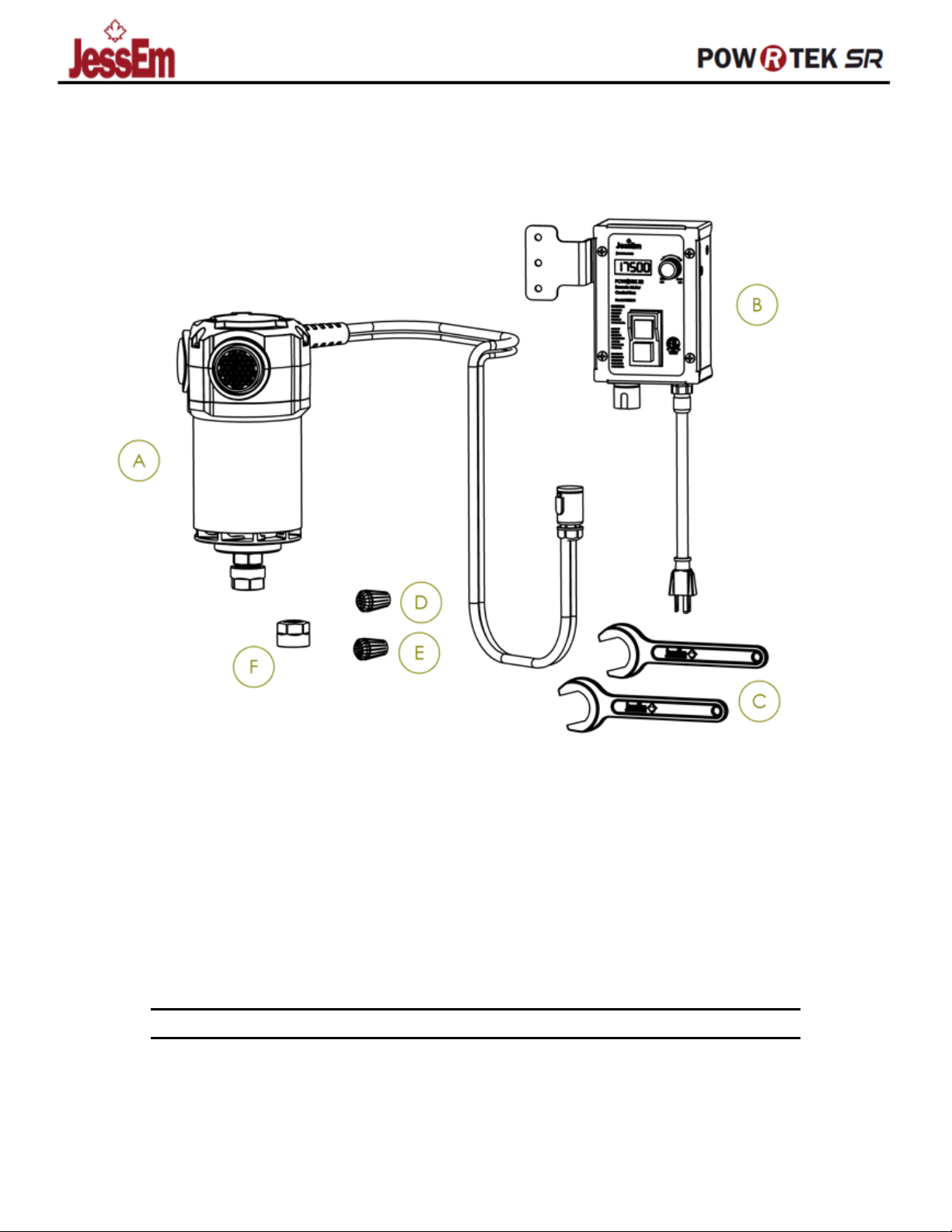
Figure 1 – What’s included with the POW-R-TEK SR ROUTER
SPECIFICATIONS
AC VOLTAGE
230 V (50 Hz)
POWER CONSUMPTION
2400 W (INPUT) 1800 W (OUTPUT)
NO LOAD RPM
10 000 – 22 000
A
ROUTER
D
½” ER-20 COLLET
B
SPEED CONTROL BOX
E
¼” ER-20 COLLET
C
WRENCHES
F
ER-20 COLLET NUT

JessEm.com FOR TECHNICAL SUPPORT CALL 1-800-436-6799
Page3
WARRANTY
JESSEM TOOL LIMITED WARRANTY
All JessEm products are warranted to be free
from defects in material and workmanship.
JessEm will repair or replace any product which
upon inspecon proves to be defecve for a
period of (1) year from dated receipt and proof of
purchase. All warranty claims should be made
direct to JessEm Tool Company.
Contact JessEm for a warranty claim return
authorizaon and instrucons to proceed. The
consumer is responsible for shipping costs to
return product to JessEm Tool Company. We will
repair or replace the product at our discreon
and JessEm Tool will return shipment to you at no
charge.
WARRANTY LIMITATIONS
This warranty does not cover:
• Repairs or alteraons made or aempted by
anyone other than JessEm Tool Company or an
authorized JessEm service professional.
-Normal wear and tear
-Abuse, misuse or neglect.
-Improper care or maintenance.
-Connued use aer paral failure.
-Products that have been modied in any
way.
-Products used with improper accessories

JessEm.com FOR TECHNICAL SUPPORT CALL 1-800-436-6799
Page4
GENERAL SAFETY
WORK AREA
1Keep work area clean and well lit. Cluer and dark
work areas invite accidents.
2Avoid dangerous environments. Do not use your
power tool in the rain, damp or wet locaons or in the
presence of an explosive atmosphere (gaseous fumes,
dust or ammable materials). Remove materials or
debris that may be ignited by sparks.
3Keep bystanders away. Children and bystanders
should be kept at a safe distance from the work area
to avoid distracng the operator and contacng the
tool or extension cord.
4Protect others in the work area from debris such as
chips and sparks. Provide barriers or shields as
needed.
5Make your workshop child proof with padlocks,
master switches, or by removing starter keys.
ELECTRICAL SAFETY
6Grounded tools must be plugged into an outlet
properly installed and grounded in accordance with all
codes and ordinances.
7Double insulated tools are equipped with a polarized
plug (one blade is wider than the other). This plug will
t in a polarized outlet only one way. If the plug does
not t fully in the outlet, reverse the plug. If it sll
does not t, contact a qualied electrician to install a
polarized outlet. Do not change the plug in any way.
Double insulaon eliminates the need for the three-
wire grounding power cord and grounded power
supply system.
8Guard against electrical shock. Prevent body contact
with grounded surfaces such as pipes, radiators,
ranges and refrigerators. When making blind or
plunge cuts, always check the work area for hidden
wires or pipes. Hold your tool by insulated nonmetal
grasping surfaces. Use a Ground Fault Circuit
Interrupter (GFCI) to reduce shock hazards.
9Do not expose to rain or use in damp locaons.
10 Do not abuse the cord. Never use the cord to
carry the tools or pull the plug from an outlet.
Keep cord away from heat, oil, sharp edges or
moving parts. Replace damaged cords
immediately. Damaged cords increase the risk of
electrical shock.
PERSONAL SAFETY
11 Know your power tool. Read this manual carefully to
learn your power tool’s applicaons and limitaons as
well as potenal hazards associated with this type of
tool.
12 Stay alert, watch what you are doing, and use
common sense when operang a power tool. Do not
use tool while red or under the inuence of drugs,
alcohol, or medicaon. A moment of inaenon while
operang power tools may result in serious personal
injury.
13 Dress properly. Do not wear loose clothing or jewelry.
Wear a protecve hair covering to contain long hair.
These may be caught in moving parts. When working
outdoors, wear insulated non-skid footwear. Keep
hands away from moving parts. Do not wear gloves,
as they can potenally get caught in rotang parts and
pull your hand into the cuer.
14 Reduce the risk of unintenonal starng. Be sure your
tool is turned o before plugging it in. Do not use a
tool if the power switch does not turn the tool on and
o. Do not carry a plugged-in tool with your nger on
the switch.
15 Remove all adjusng keys and wrenches. Make a habit
of checking that adjusng keys, wrenches, etc. are
removed from the tool before turning it on.
16 Do not overreach. Maintain control. Keep proper
foong and balance at all mes.
17 Use safety equipment. Everyone in the work area
should wear safety goggles or glasses with side shields
complying with current safety standards. Everyday
eyeglasses are not safety glasses. Wear hearing
protecon during extended use and a dust mask for
dusty operaons. Hard hats, face shields, safety shoes,
etc. should be used when specied or necessary. Keep
a re exnguisher nearby.
18 Keep guards in place and in working order.
19 Never stand on tool. Serious injury could occur if the
tool is pped or if the cung tool is unintenonally
contacted.
20 Keep hands away from all cung edges and moving
parts.
21 Never touch the bit during or immediately aer use.
Aer use the bit may be hot enough to burn bare skin.

JessEm.com FOR TECHNICAL SUPPORT CALL 1-800-436-6799
Page5
TOOL USE AND CARE
22 Secure work. Use clamps or a vise to hold work when
praccal. It is safer than using your hand and it frees
both hands to operate the tool.
23 Do not force tool. Your tool will perform best at the
rate for which it was designed. Excessive force only
causes operator fague, increased wear and reduced
control.
24 Use the right tool. Do not use a tool or aachment to
do a job for which it is not recommended. For
example, do not use a circular saw to cut tree limbs or
logs. Do not alter a tool.
25 Unplug tool when it is not in use, before changing
accessories or performing recommended
maintenance.
26 Store idle tools. When not in use, store your tool in a
dry, secured place. Keep out of reach of children.
27 Never leave the tool running unaended. Turn power
o. Do not leave the tool unl it comes to a complete
stop.
28 Check for damaged parts. Inspect guards and other
parts before use. Check for misalignment, binding of
moving parts, improper mounng, broken parts and
any other condions that may aect operaon. If
abnormal noise or vibraon occurs, turn the tool o
immediately and have the problem corrected before
further use. Do not use a damaged tool.
29 Use proper accessories. Consult this manual for
recommended accessories. Using improper
accessories may be hazardous. Be sure accessories are
properly installed and maintained. Do not defeat a
guard or other safety device when installing an
accessory or aachment.
30 Maintain tools carefully. Keep cung edges sharp and
clean. Follow instrucons for lubricang and changing
accessories. Periodically inspect tool cords and
extension cords for damage. Have damaged parts
repaired or replaced by a JESSEM.
31 Maintain labels & nameplates. These carry important
informaon.
32 Read, understand, and follow the instrucons
packaged with the router table and router li. Do not
plug in Remote Power unl Router Table Motor is fully
installed
33 Only use the following recommended router tables
and router lis with this motor.
-JessEm Mast-R-Li II #02120/21/23
-Incra Mast-R-Li II #02121
- JessEm Mast-R-Li Excel #02202
-JessEm Mast-R-Li Excel II #02203
Using tables and lis that are not specically
recommended may not properly secure the Router
Table Motor. An improperly secured Motor increases
the risk of injury or product damage.
34 Do not place motor in a router base or hold motor by
hand during use. Motor is designed only for use
properly secured in a recommended JessEm router li
or router table. This motor is not designed for use in a
router base.
35 Some woods contain preservaves that can be toxic.
Take extra care to prevent inhalaon and skin contact
when working with these materials. Request, and
follow, any safety informaon available from your
material supplier.
36 Always make sure the workpiece is free from nails,
screws and other foreign objects. Keep the working
edge away from the clamping surface. Cung these
objects can cause loss of control of the workpiece and
damage to the bit.
37 Never place hands near cung surface.
38 Never use dull or damaged bits. Sharp bits must be
handled with care. Damaged bits can break during
use. Dull bits require more force, which could cause
the bit to break. Damaged bits can throw carbide
pieces and burn the workpiece.
39 Never use dull or damaged bits. Sharp bits must be
handled with care. Damaged bits can break during
use. Dull bits require more force, which could cause
the bit to break. Damaged bits can throw carbide
pieces and burn the workpiece.
40 Never start the tool when the bit is in contact with the
material. The bit cung edge may grab the material
causing loss of control of the workpiece.

JessEm.com FOR TECHNICAL SUPPORT CALL 1-800-436-6799
Page6
SERVICE
41 Service or maintenance performed by unqualied
personnel may result in a risk of injury.
42 When servicing a tool, use only idencal
replacement parts. Follow instrucons in the
maintenance secon of this manual. Use of
unauthorized parts or failure to follow
maintenance instrucons may create a risk of
shock or injury.
GROUNDING
43 Double insulated tools are constructed throughout
with two separate "layers" of electrical insulaon
between you and the tool's electrical system.
Tools built with this insulaon system are not
intended to be grounded. NOTE: Double insulaon
does not take the place of normal safety
precauons when operang this tool, the
insulaon system is for added protecon against
injury resulng from a possible electrical
insulaon failure within the tool.
44 If the tool is supplied with a 3-prong plug, it must
be plugged into a 3-contact electrical receptacle.
The 3rd prong is used to ground the tool and
provide protecon against accidental electric
shock.
EXTENSION CORDS
45 Grounded tools require a three-wire extension
cord. Double insulated tools can use either a two
or three wire extension cord.
46 As the distance from the supply outlet increases,
you must use a heavier gauge extension cord.
Using extension cords with inadequately sized
wire causes a serious drop in voltage, resulng in
loss of power and possible tool damage. Refer to
the table shown to determine the required
minimum wire size.
47 The smaller the gauge number of the wire, the
greater the capacity of the cord. For example, a
14-gauge cord can carry a higher current than a
16-gauge cord. When using more than one
extension cord to make up the total length, be
sure each cord contains at least the minimum wire
size required.
48 If you are using one extension cord for more
than one tool, add the nameplate amperes
and use the sum to determine the required
minimum wire size.
49 If using an extension cord outdoors, be sure it
is rated for outdoor use (Typically marked
with the sux “W-A” or “W” in Canada).
50 Be sure your extension cord is properly wired
and in good electrical condion. Always
replace a damaged extension cord or have it
repaired by a qualied person before using it
51 Protect your extension cords from sharp
objects, excessive heat and damp or wet
areas.
52 Avoid stepping on your extension cord.
53 If in Doubt about the rang or safety of an
extension cord, consult an electrician or other
qualied person.
READ AND SAVE ALL
INSTRUCTIONS FOR FUTURE USE

JessEm.com FOR TECHNICAL SUPPORT CALL 1-800-436-6799
Page7
TOOL ASSEMBLY
WARNING: To reduce the risk of injury, always
unplug tool before aaching or removing
accessories or making adjustments. Use only
specically recommended accessories. Others
may be hazardous.
Snap the nut and collet together by rmly applying
downward pressure into the assembly with the palm of
your hand (Fig. 3).
To remove the collet from the nut, hold the nut rmly
with one hand and press the collet to one side with the
other hand (Fig. 4).
Collets
The collet must be aached to the collet nut before it is
put into the collet seat. Be sure that the size of the collet
matches the size of the bit shank being used. If the wrong
size bit shank is used, the collet may break. For aaching
or detaching the collet nut to the collet, follow the
illustrated instrucons on this page.
To aach the collet nut to the collet, place the narrow
end of the collet on an even surface. Take the nut and
place it over the collet (Fig. 1).
Posion the nut squarely over the collet with the smaller
opening of the nut facing up (Fig. 2).
WARNING: To reduce the risk of injury, always
wear eye protecon and all other applicable
personal protecve equipment when using or
performing maintenance on your tools.
INSTALLING THE MOTOR INTO A
LIFT
To install the motor into a router li, read, understand,
and follow the instrucons packaged with the router li.
To reduce the risk of injury, use only the following router
tables and lis with this motor.
-JessEm Mast-R-Li II™ #02120, #02121
-JessEm Mast-R-Li™ #02101, #02102
-JessEm Mast-R-Li Excel II™ #02202
-JessEm Mast-R-Li Excel™ #02201
Using other tables and lis may not properly secure the
Router Motor. An improperly secured motor increases the
risk of injury or product damage.

JessEm.com FOR TECHNICAL SUPPORT CALL 1-800-436-6799
Page8
INSTALLING THE ROUTER BIT
It is not necessary to remove the motor from the li
to install a collet assembly or a bit. (If removal of
the motor is desired, see the li instrucons.) Raise
the motor as high as possible. Always wipe wood
chips, dust or other foreign materials from the collet
sha and collet assembly before assembling.
1. Insert the collet assembly into the collet seat.
2. Insert the bit shank into the collet as far as it will
go.
3. Back the bit shank out slightly to avoid
booming out.
Be sure there is a minimum of 1/16" between the
boom of the collet assembly and the radius to the
cung poron of the bit (Fig. 5).
4. Be sure that the collet is not clamped to a
uted secon on the bit shank. The collet
should be clamped to a solid part on the bit
shank.
5. To ghten the bit in the collet assembly, use
two wrenches (Fig. 6).
NOTE: Never ghten a collet assembly without
inserng a bit shank of the proper size. This may
damage the collet.
x
WARNING: To reduce the risk of injury, always
check for damage on your tools and cuers
before operang. Ensure collet is properly
ghtened to prevent the bit from moving or
coming out during operaon.
x
REMOVING THE ROUTER BIT
6. Loosen the collet nut from the collet seat using
two wrenches.
7. Once loose, unscrew the collet nut by hand unl it
feels ght again.
8. Return to using the wrenches unl the bit shank
can be pulled out.
OPERATION
x
WARNING: Do not use this router unless it is
securely installed into a recommended
JessEm li and table
x
THE VARIABLE SPEED DIAL
The variable speed dial allows the user to adjust the
rotang speed (RPM) of the tool. Variable speed dial
sengs range from 10,000 RPM to 21,000 RPM.
Higher numbers correspond to higher speeds and
lower number correspond to lower speeds. To change
the speed, set the variable speed control dial to the
desired number.
Use the following chart to determine the best speed for
the bit diameter.
JessEm.com FOR TECHNICAL SUPPORT CALL 1-800-436-6799
Page9
STARTING AND STOPPING THE MOTOR
To start the motor, press the green start buon. It
will stay pressed unl the stop buon is pressed or
the incoming power is lost (power outage etc.). To
stop the motor, push the red stop buon.
ELECTRONIC OVERLOAD PROTECTION
Before the motor is overloaded, the electronic
overload protecon circuit will turn o the tool. If
the motor shuts o during use, push the o buon.
Wait at least three (3) seconds. This will reset the
electronics in the tool. Press the green start buon
to connue use.
SOFT START
The So-Start feature reduces the amount of torque
reacon to the tool. This feature gradually increases
the motor speed up from zero to the speed set by
the variable speed dial.
FEEDBACK CONTROL
The electronic speed control system allows the tool
to maintain constant speed between no-load and
load condions
MAKING THE CUT
The speed and depth of cut will depend largely on
the type of material being worked. Keep the cung
pressure constant but do not use excessive force so
the motor speed slows excessively. It may be
necessary on exceponally hard woods or problem
materials to make more than one pass to get the
desired depth of cut.
x
Before beginning the cut on the actual workpiece, it
is advisable to take a sample cut on a scrap piece of
lumber. This will show you exactly how the cut will
look as well as enable you to check dimensions.
x
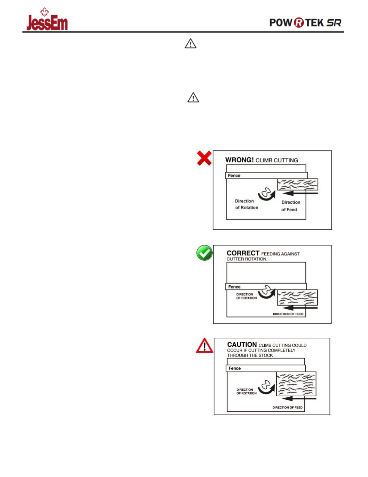
Posion the fence so that the workpiece feeds
against the cuer rotaon. Feeding the workpiece
with the cuer rotaon is called climb cung, which
is very dangerous. Climb cung can result in the
workpiece being thrown violently out of your control
at great speed.
WARNING: To reduce the risk of injury, avoid
“climb cung.” Climb cung can cause the
workpiece to be thrown violently out of your
control. Even small router bits can cause in
climb cung.
WARNING: To reduce the risk of injury, always
use feather boards, push scks or push blocks
with proper guarding. Keep hands away from
moving bit. Refer to the Router Table manual
for proper table setup and use.

JessEm.com FOR TECHNICAL SUPPORT CALL 1-800-436-6799
Page10
MAINTENANCE
WARNING: To reduce the risk of injury,
always unplug your tool before performing
any maintenance. Never disassemble the
tool or try to do any rewiring on the tool's
electrical system.
WARNING: To reduce the risk of injury,
electric shock and damage to the tool, never
immerse your tool in liquid or allow a liquid
to ow inside the tool
MAINTAINING TOOL
Keep your tool in good repair by adopng a regular
maintenance program. Before use, examine the
general condion of your tool. Inspect guards,
switches, tool cord set and extension cord for
damage. Check for loose screws, misalignment,
binding of moving parts, improper mounng, broken
parts and any other condion that may aect its safe
operaon. If abnormal noise or vibraon occurs, turn
the tool o immediately and have the problem
corrected before further use. Do not use a damaged
tool. Tag damaged tools “DO NOT USE” unl repaired
(see “Repairs”).
CLEANING
Clean dust and debris from vents. Keep the tool
handles clean, dry and free of oil or grease. Use only
mild soap and a damp cloth to clean your tool since
certain cleaning agents and solvents are harmful to
plascs and other insulated parts. Some of these
include: gasoline, turpenne, lacquer thinner, paint
thinner, chlorinated cleaning solvents, ammonia and
household detergents containing ammonia. Never
use ammable or combusble solvents around tools.
ACCESSORIES
WARNING: To reduce the risk of injury,
always unplug the tool before aaching or
removing accessories. Use only specically
recommended accessories. Others may be
hazardous
For a complete lisng of accessories, including JessEm
router tables and lis, visit JessEm at www.jessem.com or
contact a distributor near you
The following JessEm lis accept the JessEm Motor with
Control Box.
-JessEm Mast-R-Li™ #02101, #02102
-JessEm Mast-R-Li II™ #02120, #02121
-JessEm Mast-R-Li™ Excel #02201
-JessEm Mast-R-Li™ Excel II #02202

1
2
3
45
6
7
8
9
10
11
12
13
14
15
16
17
18
19 20
21
23
24
25
Exploded Drawing
Model No.: 05302
Parameters: 230V 50 Hz
No Load Speed: 10,000 - 21,000 RPM
22
26
27
28 29 30
31
32
33 34 35 36 37
38
39
40
41
42

05300 Router Motor Explosion view Parts List
Part No. Index Part No. Part Name QTY
1 05300-001 Collet Nut 1
2 05300-002 1/2" Collet 1
3 05300-003 Collet Seat 1
4 05300-004 Face Plate Screws 6
5 05300-005 Face Plate 1
6 05300-006 Angular contact Spindle Bearings 2
7 05300-007 Aluminum Housing 1
8 05300-008 Inner housing Sleeve 1
9 05300-009 Armature/fan assembly 1
10 05300-010 Upper Bearing Seat 1
11 05300-011 Bearing Seat Screws 4
12 05300-012 Upper Bearing 1
13 05300-013 Magnetic sensor screw 1
14 05300-014 Stator Winding Assembly 1
15 05300-015 Lower Plastic housing 1
16 05300-016 Air Intake port 2
17 05300-017 Brush Holder assembly 2
18 05300-018 Brush 2
19 05300-019 Brush Holder Screws 4
20 05300-020 Lower Plastic housing screws 3
21 05300-021 PCB Tray 1
22 05300-022 PCB tray screws 4
23 05300-023 Main PCB 1
24 05300-024 Upper Plastic Housing 1
25 05300-025 Upper Plastic housing screws 3
26 05300-026 Router to Controller Connection 1
27 05300-027 Control Box Face plate 1
28 05300-028 Mounting Bracket screws 2
29 05300-029 Mounting Bracket 1
30 05300-030 Control Box Face Plate Screws 4
31 05300-031 Ground Wire Mounting Screw 1
32 05300-032 Control Box 1
33 05300-033 Electromagnetic Saftey Switch 1
34 05300-034 Display Screws 1
35 05300-035 Speed display Board 1
36 05300-036 Plug mounting screws 4
37 05300-037 Wire mount Fitting 1
38 05300-038 Potentiometer 1
39 05300-039 Speed adjustment Knob 1
40 05300-040 Power Cord 1
41 05300-041 1/4" Collet 1
42 05300-042 Wrench 2
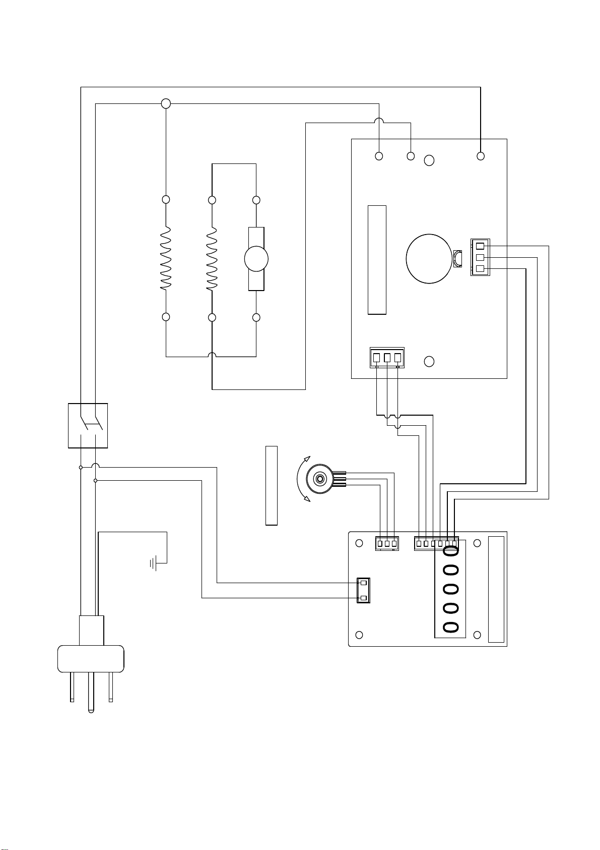
Model No.: 05300
Motor Parameters:
120V 60Hz 15A No
Load Speed:
10,000~21,000 RPM
Speed Adjustment
Potentiometer
5 34
HL
Motor Control PCB
M
main winding -R
Main winding-L
Brush-R Brush-L
3
4
65
7
8
3
4
5
5
4
3
L AC N
8 7 6
Power
ON/OFF
Speed Display PCB
Ground
This manual suits for next models
2
Popular Safety Equipment manuals by other brands


Save Phace
Save Phace I Series owner's guide

WISENT
WISENT 20826240 operating instructions

Berner
Berner 362968 operating instructions

Pizzato Elettrica
Pizzato Elettrica CS AR-91 Series operating instructions

Omron
Omron F3S-AP Series manual

Tractel Group
Tractel Group Stopfor M Series Operating and maintenance instructions


