JET Performance Products V-FORCE Plus Operation manual

V-FORCE Plus™
Engineered For Power!
INSTALLATION & USER GUIDE
© 2015 JET Performance Products
WARNING!!!
DO NOT OPERATE
WHILE DRVING!!

-1-
Installation Instructions
JET V-Force
1. Mounting the V-Force
Using the supplied Velcro, Suction Cups or L-Brackets, locate the V-Force
in a convenient location that does not obstruct your view.
TIP: Clean the mounting area with alcohol or another nonabrasive cleaner
to ensure the Velcro or Suction Cups adhere properly.
2. Disconnect the Negative Battery Cable
Locate the battery and remove the negative battery cable.
3. Routing the Wiring Harness
The wiring harness must be routed through the rewall to reach under the hood.
Under the dash near the location that you mounted the V-Force locate an
existing plug or wiring harness that goes out under the hood and route the
V-Force / PCU wiring through the rewall.
TIP: Make sure the wiring harness does not interfere with any moving parts (i.e.: gas
or brake pedal) or touch anything under the hood that produces excessive heat,
such as the exhaust system.
4. Connecting the V-Force + 12 V Power Connection
(RED WIRE)
Locate the vehicles fuse box. It is normally located on the drivers side of the
vehicle under the dash or in the driver’s side kick panel or under the hood.
Included in the V-Force installation parts you have two brass fuse
adaptors. Depending on which type of fuses your vehicle uses, select the
one that ts your type of fuse. Connect the fuse adaptor to a fuse that has +12
volts all the time. Connect the RED WIRE from the V-Force to the
fuse adaptor you just installed.
5. Connecting the V-Force ground wire (BLACK WIRE)
Connect the BLACK WIRE from the V-Force to a suitable ground point.
Existing screws or nuts that are attached to metal are a good location for this
purpose.
6. Connecting the TPS (Throttle Position Sensor) Wire
(BROWN WIRE)
Using the V-Force / PCU wiring pin out chart (included) locate the correct
wiring color and location of the TPS for your vehicle.After locating the TPS you
will note that the TPS has multiple wires going to it. Crimp a RED Scotch lock
connector (this is the type that wraps around the wire and is then crimped closed
to pierce the wire) to the wire color that matches the chart for your vehicle. Plug
the BROWN WIRE from the V-Force into the scotch lock connector.

-2-
7. Connecting the MAP (Manifold Absolute Pressure) / MAF
(Mass Air Flow Meter) Input Wire (GREY WIRE)
Use the V-Force wiring chart to determine the correct wire color and
if you will be connecting to the MAP or MAF sensor (Most vehicles will be con-
necting to the MAP. There will be a note on the wiring chart for your specic
vehicle if your vehicle connects to the MAF). CUT the wire color that matches
the chart for your vehicle about 2 inches away from the sensor, leaving enough
room to crimp on a new connector. Strip about 1/4 of an inch of insulation off
of both ends of the wire that you just cut. Crimp a PINK MALE spade connec-
tor to the portion of the wire that is still attached to the MAP / MAF Sensor.
Plug the GREY WIRE from the V-Force into the PINK MALE connector that
is now attached to the MAP / MAF wire.
8. Connecting the MAP (Manifold Absolute Pressure) / MAF
(Mass Air Flow Meter) Output Wire (GREEN WIRE)
Crimp a PINK FEMALE spade connector to the other portion of the above wire
that you previously stripped. Plug the GREEN WIRE from the V-Force
into the PINK FEMALE connector that you just attached.
9. Securing the wiring harness
Route the wiring harness away from any moving engine parts or any exhaust
components. With the supplied cable ties you can now secure the wiring harness
away from any moving engine parts or anything that may get hot enough to melt
the wiring insulation.
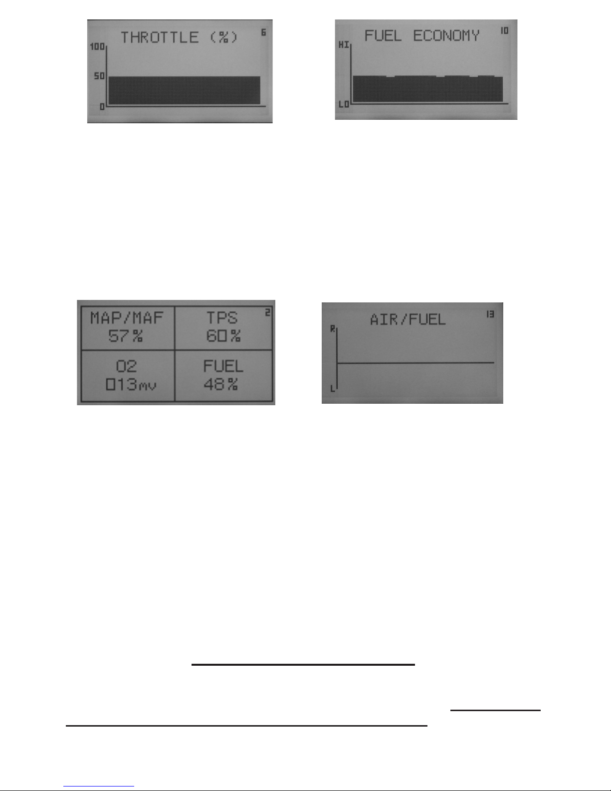
OPTIONAL: Air/Fuel Monitor
The PURPLE WIRE is for the air/fuel meter in the V-Force Plus. This optional
connection will allow you to monitor your vehicles air/fuel mixture ratio in mil-
livolts or in graph form on the screen.
Because of the many types of Oxygen Sensors in vehicles today, you will
need access to a factory repair manual that has wiring diagrams for your specic
vehicle or there are online sources such as Prodemand.com or Alldata.com that
can provide wiring diagrams online for a minimal fee.
You will be connecting the PURPLE WIRE from the V-Force Plus to the
OXYGEN (O2) SENSOR SIGNAL wire. The sensor is located in the exhaust
system, on applications that use multiple sensors, make sure that you connect
to a sensor that is located before the Catalytic Converter or you will not get
accurate readings.

OPERATING THE V-FORCE PLUS
Reconnect the negative battery cable that you removed during the rst part
of the installation.
1. The Power Button (PWR) will turn the unit ON / OFF. When Power-
ing the V-Force Plus for the rst time, the display will show the
Jet Logo then display the version number of the current software.
The V-Force Plus can be left ON from this point. The unit will
go into StandBy mode when the vehicle is turned off and will come out
of StandBy mode when the vehicle is restarted. After the rst power
up the V-Force / PCU Plus will automatically revert back to the last
screen used the next time you start the vehicle.
2. The Arrow Buttons allow the user to scroll forward or back through
the screens.
3. The DIM button adjust the Brightness of the display, by repeatedly
pressing the DIM button the Brightness will continue to increase.
4. Pushing the DIM button and then using the arrow keys, you can control
the contrast of the display.
-3-
SCREENS
The V-Force has fourteen different screens to chose from. These screens
allow the user to monitor the following vehicle sensors. Manifold Absolute Pressure /
Mass Air Flow; Throttle Position; Battery Voltage; Fuel Economy; Air / Fuel mixture
ratio ( Please see OPTIONAL for O2 sensor connection ). The display makes use of
three different types of display. A Bar Graph, Line Graph and Data Display.
NOTE: Some vehicles that connect to the MAF Sensor may not get ac-
curate readings or may not receive any readings at all on the MAP/MAF or
Fuel Economy screens.

-4-
Reading the Air/Fuel Meter:
The Oxygen Sensor must be at operating temperature before you will get any reading
on the screen, normally it must reach 600 degrees F before you will get an accurate reading.
Once up to operating temperature at idle and cruise the air/fuel ratio will cycle up and down,
this is normal, it is the vehicles PCM trying to maintain a perfect air/fuel ratio. this ratio is
called stoichiometric, at this ratio all of the fuel and oxygen is burned. During accleration you
will notice that the meter will move to a richer mixture, this is also normal, by accelerating
you have increased the amount of fuel the sensor is reading.
TECHNICAL ASSISTANCE
Technical Assistance is available Monday through Friday between 8:00 am and 5:00 pm
Pacic Standard Time. Technical Assistance is provided by Jet Performance Products by
THE PLACE OF PURCHASE FOR TECHINCAL ASSISTANCE

JET Performance Products
17491 Apex Circle
Huntington Beach, CA 92647
(714) 848-5515 • Fax: (714) 847-6290
www.JETCHIP.com
V F-UG 4/14
Limited Warranty
Jet Performance Products warrants Chips and Modules to be free from defects in
material and workmanship under normal use and if properly installed. This limited 1 year
warranty is to the original purchaser, provided all information requested is furnished. If
found to be defective as mentioned above, it will be replaced or repaired at the sole discre-
tion of Jet if returned prepaid along with proof of purchase.
All other products and services performed by Jet are warranted to be free of
defects in material and workmanship for a period of 6 months from date of purchase. This
warranty is to the original purchaser. Repair, Replacement or Credit will be based on the
date of purchase. Costs for labor are specically excluded and are the sole responsibility of
the purchaser.
This warranty does not apply to Custom Programming or any product incorrectly
installed, modied by the purchaser, or to any product that has been subjected to misuse,
negligence or accident.
To obtain warranty service and Return Authorization Number, contact our Cus-
tomer Service Department at 714-848-5515 between 8 am and 5 pm Pacic Standard Time,
Monday through Friday.
Defective Products may be brought or sent prepaid (with Return Number) to Jet
Performance Products, 17491 Apex Circle, Huntington Beach, CA 92647.
For Warranty Registration go to www.jetchip.com/register.asp
Table of contents
Other JET Performance Products Automobile Accessories manuals
Popular Automobile Accessories manuals by other brands

Webasto
Webasto Hollandia 700 operating instructions

BENQ-SIEMENS
BENQ-SIEMENS Car Kit Bluetooth Portable manual

rough country
rough country 921107830 Installation instruction

Free2Move eSolutions
Free2Move eSolutions PowerMeter Installation and user manual

Kuda
Kuda 043190 installation instructions

BASETech
BASETech BT-372788 operating instructions