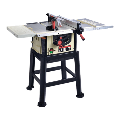
Jet JCS-10 User manual

'"
J
t=T
Jes~;o
SHOWN
WITH ACCESSORY
STAND AND
ELECTRICALS
The Seriai No.
and
Model No. plate is attached
to the rear brace
of"
the saw cabinet, Locale
this
plate
and
record the Seriai No.
and
Model
No. in your
,,(l1anual
for future reference.
SERIAL
NO.
------------,-
MODEL NO.
__________
___


8.
WHEN
cutting mouldings, NEVER
run
the stock
· bétween the tence
and
the
moulding
cutterhead.. Refer
to
mould.ing applications
.ir\
lnstr~ction
Manual.for
details.
.9..
DIRECTION OF
FEED..
Feed work
into
à blade
or
cutter against the
direction
or' rotation of the blade
or.
cutter only.
10. NEVER use the tence as a eut-off gage
when
cross
cutting.
11.
NEVER
attempt'
to
free a
stalled
saw blàde without
first
turning the saw
OFF.
·
12. PROVIDE adequate support
to
the rear
and
sidas
of the
saw
table· for
wide
or long workpieces.
13. AVOlD KICKBACKS (work thrown back
tow.ard
yeu)
by keeping blade shf!rp, keeping
rip
fence p;Jrallel_
to
the saw blade, keepirig
splitter
and
antikickback
fingers
and
guard in place
and
operating, by not releasing .work
bef
ore
i't is pushed aIl the way past the saw blade,
and
by not ripping work that is twisted
or
warped
or
does not have a
straight
edge to guide along the tence.
14. AVOlD. awkward . operations
and
hand
positions
where a sudden s1ip cou
Id
cause your
ha
nd
to
move
into
the
cutting
tool.
UNPACKING
Carefully unpack the saw
and
ali
loose items from
the carton.
Fig.
2,
illustrates
ali
.the 1
oose
items
packed with your
saw.
1
t>'
,:·;;~
?Rfiii"O
,.,~t"
1 Guide Rails
Fig.
2
2 Extension
Wings
3 See-Thru Blade Guard
and
Splitter
4 Miter
Gage
5
Belt
and
Pulley Guard
7 Rip Fence
8
V-Belt
9 Motor Pulley
10
Hardware for Extension
Wings
15
11
Blade
Guard
and
Splitter Mounting Hardware
12
Tilting
and
Raising Lock Knobs, Switch Bracket,
Motor Mounting Hardware, Guide Rail Hardware
13 Motor Mounting Plate
14 Motor Mounting Plate Bracket
15 Arbor
Wrench
16
Raising
and
Tilting
Handwheels
3

SAFETY
RULES
FOR
ALL
lOOLS
As
with
ali power
tools
the
re
is
a certain amount
of
hazard involved ·with
the
operator
and
tas
use
'Of
the
tool. Using
the
tool with the respect
and
caution
demanded
as far
as
safety
precautions
are concernod will
considerably
lr;:!ssen
the possibility
of
persona-!
injury.
However,
if
normal safet)' precautions
are
overlooked
or
completely
ignored, persona! in
jury
to
the
operator
can
develop.
1. KNOW YOUR
POWER
TOOL.
Read
the owner's manual
carefully. Learn
the
tools
applications
and
limitations, as weil
as
the specifie potential hazards peculiar
ta
it.
2.
KEEP GUARDS IN PLACE
and
in working order.
3. GROUND
ALL
TOOLS.
If
tool
is
equipped with three·
prong plug,
it
should
be
plugged into a three·hole electrical
receptacle.
If
an adapter
is
used
to
accommodate a two-prong
receptacle,
the
adapter
lug
must
be
attached
to
a known
grou nd. Never remove
thetftird
prong.
4. REMOVE ADJUSTING KEYS
AND
WRENCHES. Form
habit of ·checking
ta
see
that
keys and adjusting wrenches are
removed from tool before turning
iton.
5.
KEEP WORK
AREA
CLEAN. Cluttered
areas
and
benches invite accidents.
6.
AVOlD
DANGEROUS ENVIRONMENT. Don't
use
power tools
in
damp
or
wet
locations, or expose them
to
ra
in.
Keep work area weil lighted.
7. KEEP CHILDREN
AND
VISITORS AWAY. Ali children
and vîsitors should be
kept
a safe distance from work area.
8.
MAKE
WORKSHOP KIDPROOF ·
with
padlocks, master
switches; or by removing starter keys.
9.
DON'T
FORCE TOOL.
lt
will
do the job better
and
be
safer at
the
rate for which it was designed.
10.
·use
RIGHT TOOL.
Don't
force tool
or
attachment
to
do a job
it
was
not
designed for.
11. WEAR
PROPER
APPAREL. No loose clothing,
gloves,
neckties,
or
jewelry
to
get caught
in
moving parts. NonsiiP
footwear
is
recommende.:l. Wear protective hair covering
to
conta
in
long hair.
12.
USE
SAFETY GLASSES. Also
use
face
or dust
mask
if
cutting operation
is
dusty.
13. SECURE WORK.
Use
clamps or a
vise
to
hold work,
when practical. lt's safer than using
your
hand.and frees
bath
hands
to
operate tool.
14.
DON'T
OVERREACH.
Keep
your proper footing
and
balance
at
ali
times.
15.
MAINTAIN
TOOLS IN
TOP
CONDITION.
Keep
tools
sharp and clean for best and safest performance. Fol!ow
instructions for lubricating
and
changing accessories.
16.
DISCONNECT TOOLS before servicing
and
when
changing accessories such as blades,
bits.,
cutters.
17.
USE
RECOMMENDED ACCESSORIES. Consult the
owner's manual. for recommerided ·accessories.
The
·use
of
improper accessories may cause haz'ards.
18.
AVOlD
ACCIDENTAL STARTING.
Make
sure
switch
is
in
"OFF"
position before plugging
in
cord.
19. NEVER STAND
ON
TOOL. Serious injury could occur
if the tool
is
tipped
or
if
the
cutting tool
is
accidentally
contacted.
·
20. CHECK
DAMAGED
PARTS. Before further
use
of the
tool, a guard
or
other
part
that
is
damaged should be carefully
checked
to
ensure
that
it will operate properiY and perform its
intended function -check for alignment of moving parts,
binding of moving parts, breakage
of
parts, mounting, and any
other
conditions
that
may affect its operation. A guard or
other part that
is
damaged
should
be
properly repaired or
replaced.
21. DIRECTION OF FEED.
Feed
work
into a
blade
or cutter
against the direction
of
rotation
of
the
bladé
or
cutter
only.
22. NEVER LEAVE TOOL RUNNING UNATTENDED.
TURIN
POWER
OFF.
Don't
leave
tool until
it
comes
to
a
comflete stop.
23. DRUGS, ALCOHOL, MEDICATION. Do not oper·
ate
tool
while under the influence
of
drugs, alcohol
or
any
medication.
ADDITIONAL
SAFETY
RULES
FOR
CIRCULAR
SAWS
1.
ALWAYS
use
guard,
splitter
and
anti-kickback
fingers
on
ali
"thru-sawing"
operations. Thru-sawing
operations are those when the blade cuts. completely
through .the work piece as in rlpplng or cross
cutting.
2. ALWAYS hold the work
firmly
against the miter
gage or fence.
3. ALWAYS use a push
stick
for
ripping narrow
stock.
Refer
ta
ripping
applications
in
instruction
manual
where
push
stick
is covered
in
delai
1.
2
4.
NEVER
perform any operation
"free-hand"
which
means using your hands
to
support
or
guide the work
piece.
Always
use
either
the tence or the miter
gage
to
position
and guide the work·.
s.
NEVER stand
or
have any part of your body in
line
with
the path
of
the saw blade,
6.
NEVER
reach behind
or
over lhe
cutting
tool
with
either
hand for any reason.
1.
MOVE the
rip
tence out
of
the way when .cross
cutting.

ASSEMBLING
STAND
If
you purchased the Stand assemble the stand
as shawn in
Fig.
3, 1 using the
Scr\3ws
and
nuts
supplied.
On/y tighten the screws
and
nuls
linger
tight
at
this
time.
NOTE:
Fig.
4,
illustrates
the
proper
re/ationshlp
of the screws and nuts to the
stand.
Place the stand
on
a leve/ surface and tighten the
screws
and
nuts,
Fig. 3
ASSEMBLING
SAW
TO
STAND
OR
BENCH
Assemble the
saw
to
the Steel Stand.
IMPORTANT:
If the
saw
is
to
be
used without the Steel Stand.
We
suggest that
it
a/ways
be
fastenec to a supporting surface
using the ho/es
on
the bottom
Jedge
of
the
saw
cabinet.
FASTENING
STAND
OR
BENCH
TO
FLOOR
IF
DURING
OPERATION
THERE
IS
ANY
TENDENCY
FOR
THE
TOOL
TO
TIP
OVER.
SLIDE
OR
WALK
ON.
SUPPORTING
SURFACE,
THE
STAND
OR
BENCH
MUST
BE
SECURED
TO
THE
FLOOR.
4

ASSEMBLING
MOTOR
MOUNTING
BRACKET
AND
PLATE
1. Assemble the motor mounting bracket (A)
to
the
two posts (B) and
tighten
set screws (C), as shawn
in
Fig.
5.
2. Loosen screw
thal
holds rod (D) in place and
remove rod (D) from motor mounting bracket '(A)
Fig.
5.
3. Assemble motor mounting plate (E)
Fig.
5,
to
the
motor mounting bracket (A) and reassemble rod (D)
to
the plate and bracket. Make sure screw
thal
holds
the rod (D) in place is 1ightened
into
the V·grùove
in
the rad.
RECOMMENDED
MOTOR
FOR
YOUR
SAW
The motor recommended for use
with
your saw is the
1Y,"
H,P,
Bali
Bea
ring,
Capacitor Start.
115
Volt
60
cycle
motor.
This
motor has been
specially
seleoted
to
best
supply
power
to
your machine and the
relative
safety
of the
machine
is
enhanced
by
its
use.
We
therefore strongly
suggest
thal
only
this
motor
be
used as the use of other
motors
may
lie detrimental
to
the performance and
safety
of
the saw.
Fig. 6
--MOTOR
MOIJNTING PLATE
~
---
SHAKEPROOF EXT. LOCKWASHf..R
~-;
__
--FLAT
WASHER
~----HEX
NUT
5
ASSEMBLING
MOTOR,
MOTOR
PULLEY,
BELT
&
PULLEY
GUARD,
AND
V-BELT
If
you
purchased
the
motor
recommended
for
use
with
your
saw,
make
sure
the
mot
oris
DISCONNECTED
from
the
power
source
and
assemble
it
toy
our
saw
as
follows:
L
Assemble
motor pulley (A)
Fig,6,
to
the motor shaft
with
hub
of
pulley
out.
Tighten._set..
screw
in
motor
pulley
against
key
in
motor
shaft,
as
shawn
in
Fig.
6.
2. Assemble
motor
to
m~tor
mounting
plate,
as
shawn
in
Fig
6 using the hex head screws,
flat
washers, shakeproof
lockwashers and n4!s supplied,
Do
not tighten at this lime.
3. Fig.
6A
îllustrates
the
proper
relationship
of
the
mo
tor
mounting
hardware.
CAUTION:
The
proper
grounding
of
the
mot
or,
ta
prevent
shock
hazard,
depends
on
the
use
of
the
shakeproof
lockwashers
in
the
manner
shawn
in
Fig. 6A.

4.
Assemble
the carriage boit
(A)
to
the
bel!
and pulley
guard bracket. using
the
flat
washer
(B) and nut (C). as
shawn
in
Fig.
7.
5.
Slide the belt
and
pulley guard bracket (A) between the
motor
plate and
motoi
mounting
plate,
as
shawn
in Fig.
8.
6.
Position
the
belt
and pu! ley
guard
bracket
(A)
sa
that
the
m01:Cfr
pulle\r
(B)
is
centered
and
through
the
hale
in
the
be!t and pu!ley guard bracket,
as
shawn in
Fig·.
9.
Tighten
motor
mounting
screws, washers, lockwashers
and
nuts.
7. Using_a
straight
edge, align
the
motor
pulley
to
the
Ç~.rbor
pulley.
If
necessary move
motor
pu!ley in
or
out
on
motor
shaft. NOTE:
Be
sure guard
bracket
is
still centered and
aligned
with
pulley
as
shawn in Fig.
9.
8.
Assemble
V-belt
to
the
motor
pulley and arbor
pulley
and adjust:for correct
belt
tension.
9.
Place
washer
{C),_
spacer (D)
and
washer
{E)
on
carriage
boit,
as
shawn in
i';i.g.
i
0\
1
O.
Assemble the belt and pulley caver (A)
to
the bracket
and
fasten.in
place usïng
the
wing
nut
(8),
as
shawn
in
Fig.10
and
11.
'@
/(/
E
Fig.
10
6 Fig.
11

ASSEMBLING
SWITCH
TO
SAW
CABINET
IMPORTANT:
When
assembling the
switch
to
the saw
cabinet1 make sure the ·motor power cord is NOT
conM
nected to the power·Murce.
L Remove outer hex nut from
switch
stem. Leave
shakeproof lockwasher (A)
Fig.
12,
and
inside
hex
nut
on
switch.
NOTE: The proper grounding of the
switch
to
prevent shock hazard, depends
on
the use
of the shakeproof lockwasher
in
the manner shown.
2. lnsert
switch
stem through hole
in
front of saw
cabinet making sure the keyway in the
switch
stem
is in the down
position.
3. Place
switch
bracket
(B)
Fig.
13,
on
switch
stem
with
key in
switch
bracket engaged
with
keyway in
switch
stem
and
fasten in place with hex nul (C)
thal
was removed in
STEP
1.
4. IMPORTANT:
Alter
attachlng
switch
to
cabinet
use the two
tle
straps provided and
tle
the power cord
and motor cord
to
front hole located
on
the ledge of
the saw cabinet
and
the motor cord
to
the back hole,
as shown ln
Fig.
13A.
Leave
ali
excess motor cord
hang out
of
the back of
cabinet.
5.
IMPORTANT:
We
suggest
thal
when the saw
i.s
not in use, the
switch
be
locked in the
"OFF"
position
using a padlock, as·shown in
Fig.
14.
Catalog
Padlock is
available
as
an
accessory.
Fig.
13
Fig.
13A
fig.
ASSEMBLING
RAtSING
AND
TILTING
HAN~WHEELS
AND
LOCK
KNOBS
7
Assemble the
raising
and
tilting
handwheels (A) and
lock knobs (B)
to
the
raising
and
tilting
screws, as
shawn in
Fig.
15.
Make sure the
slot
in the handwheels
enga9e with the
roll
pins. in the
raising
and
tilting
screws.

ASSEMBUNG
EXTENSION
WINGS
The extension wings are
to
be
fastened to each end
of the _table. A
straight
edge should
be
usad
ta
leve!
the extension wings
to
the
table,
To
assemble
the
extension wings
to
the saw
table,
proceed as
follows:
1.
If your saw table has through hales
on
the side
of the table,
attach
the extension
wing
ta
the
table,
as shawn in
Fig.16,
using the
screws,
washers and
nuls.
2. If your saw table has
thr~aded
hales
on
the
side
of
the table, attach the
extension
wing
ta
the table,
as shawn in
Fig.
16, using the screws and washers.
The nuts are discarded as they are not needed when
the table
is
equipped with threaded hales.
NOTE:
The saw must
be
bolted
to
the supporting
sur-
face or a sturdy ontrigger support must
be
used
if
a
table extension over
24
inches long is
_attached
to
the
saw.
Fig.
17
ASSEMBLING
BLADE
GUARD
AND
SPLITTER
ASSEMBLY
1.
Remove
cap
screw,
washer
and
outer
splitter
bracket
helder (A) Fig.
18.
Also
remove
bi
ade,
blade arbor nut
and
flan
ge
(B),
2.
Hold a straight
edge
against the
saw
arbor flange
(C)
and
splitter bracket (D) Fig.
18,
and
check
for
alignment
on
the top
and
bottom
of
the splitter bracket
(0).
If
an
adjust-
ment
is
necessary loosen
two
screws
that
hold
splitter
bracket
(D)
ta
the trunnion
and
shift the bracket (D)
ta
bring
it
into
alignment
with- saw
arbor
flange.
Then
tighten
the
two
screws
that
hold
splitter
bracket.
NOTE:
Snap
out
the
nut
retainer
in
the
splitter
bracket
_
..
to
-~make
this·
adjustment
easier
to
perform.
8
Fig.
16
ASSEMBLING
GUIDE
RAILS
1.
The
guide rail
with
the
calibrations
goes
on
the
front
of
the
saw
table
and
should
be
positioned
as
shawn
in
Fig.17.
Assemble
the
front
guide rail (F) Fig.17to the
saw
tàble
using
two
spacers
(B)
and
special
screws
(A) threaded into tapped
hales (C).
2.
Use
the
remaining
two
spacers (B)
and
special screws (A)
Fig.17,
to
attach
the
front
guide
rqil
to
the
extension
wiilgs
and
fasten
using
the
flat
washers, lockwashers
and
hex
nuts
(D)
provided.
3.
Assemble
the plain guide rail
to
the
rear
of
the
saw
table
and
extensioÎl wings in
the
same
manner
as
the
front-guide·rail.
Be
sure
bath' guide rails extend
out
ta
the
same
side
of the
saw.
Fig. 18

3. Thread nul (A)
Fig.
19, onto threaded
end
of rod
(B)
and
thread rod (B)
into
the hale 'provided in the
trunnion bracket (C) as shown.
If
necessary a rod or
pin can
be
placed
into
hole (D)
to
assis!
in
providing
leverage
when
threading the rod (B) into the trunnion
bracket. Then tighten
nul
(A) against trunnion bracket
(C),
as
Shawn.
4. Assemble bracket (A)
Fig.
20,
to
bracket (B) using
the screw, nul
and
lockwasher (C). Assemble the screw,
nul
and
Jockwasher (D)
to
bracket (A) as shown.
s.
Place bracket (B)
Fig.
20
on
rod (E) as shown,
and
fasten using the screw and
nul
(F).
6. Assemble the center portion of the
splitter
to
ihe
splitter
bracket (D)
Fig.
18,
and
replace
splitter
bracket
holder (A)
Fig.
18.
7.
Remove nul,
screw
and
lockwasher (B)
Fig.
21,
from the rear
splitter
bracket and assemble the
splitter
(A) to the bracket using the screw, nul and lockwasher
(B).
s.
Replace saw blade and using a straight edge make
sure the
splitter
(A)
Fig.
21, is in alignment
with
the
saw blade,
as
shown. If necessary, the rear mounting
bracket assembly (C) can
be
adjusted
to
bring the
splitter
into alignment
with
the saw blade. ,
Fig.
21
9

TABLE
INSERT
The
table
insert
(A)
is
placed
in
the opening in the
saw
table,
as shown in
Fig.
22,
and
should
be
leve!
with
the
surface
of
the saw
table.
To
adjust
the
table
insert
use
~
straight
edge and
screwdriver
and
turn
the
four
adjusting
screws
in
or out
until
the
insert
is
flush
with
the
table,
as shown
in
Fig.
22.
CONNECTING
SAW
TO
POWER
SOURCE
A separate electrical
circuit
should
be
used
for
your
power tools. This
circuit
should
not
be less
than
#12
wire and should be
protected
with a
20
Amp
ti
me
lag
fuse.
If
an exten·
Sion
cor,d
is
used,
use
on!y
3-wire extension cards which have 3-prong grounding
type
plugs and-_.3-pole receptacles which
accept
the
tools
plug. For distances up_to
100
feet use
#12
wire
..
For
distances
up
to
150
feet use
#10
wire. Before connecting
the
motor
ta
the
power line,.make sure
the
switch
is
in
the
"OFF"
position and be sure
that
the
electric
current
is
of
the
same
characteristics
as
stamped on
motor
nameplate. Al! li
ne
connec-
tions should make.good contact. Running on
law
voltage
will
injure the motor.
GROUNDED
OUTLET
BOX-:1
. CURRENT
"
CAR~YING
~
PRONGS
~
•
~
GROUNDING
BLADE"'
s
IS
l.ONGEST
OF
THE 3 BLADES
Fig.
23
Fig. 24
10
liS
VOLT,
SINGLE
l'HASE
OPERATION
This
tool
must be grounded
while
in
use
to
protect
the
operator
from
electric
shock.
The
motors recom-
mended
for
use
with
your
saw
are
shipped
_wir.ed
for
115
Volt,
Single
Phase, and are equipped
with
an
ap·
proved
3-conductor
cord and 3·prong grounding
type
plug
to
fit
the proper grounding
type
receptacle,
as
shown
in
Fig.
23.
The
green
conductor
in
the cord
is the grounding
wire.
Never
connect-
the
gre-en
wire
to
a 1
ive
terminal.
An adapter, shawn in
Fig.
24,
is avai lab·!e for
connect-
ing 3-prong grounding type plugs
to
2-prong
receptacles.
THIS
ADAPTER
IS
NOT
APPLICABLE
IN
CANADA.
The
green·colored
rigid
ear, lug,
etc.,
extending
from
the adapter
is
the grounding means .and must be
con-
nected
to
a permanent ground
such
as
to
properly
ground·
ed out
let
box, as shown
in
Fig.
24.

230
VOLT,
SINGLE
PHASE
OPERA
Tl
ON
The motors recommended for
use.
with
your saw are
dual voltage,
115/230
Volts
60
cycle motors. If it is
desired
to
operate your
saw
at
230
Volt. Single Phase.
it
is
necessary to reconnect the motor leads in the
motor iunction box, by following the instructions given
on
the motor nameplate.
GROUNDED
OUTLET
BOX~
CURRENT
"'1
IMPORTANT:
Make sure motor is disconnected from
power source before reconnecting motor leads.
CAR~YIN~G
PRONGS
~
•
Il
is
also
necessary to replace the 115
Volt
plug,
sup-
plied
with
the motor,
with
a 230
Volt
plug that has
two
flat,
currént·carrying
prongs in tandem, and one round
or
"U"-shaped
longer ground prong, as shawn in
Fig.
25.
This
is
used
only
with
the proper mating 3-conductor
grounding
receptacle,
as shawn in
Fig.
25.
~
GROUNDING
BLADE~
~
IS
LONGEST
OF
THE 3 BLADES
IMPORTANT:
IN A
LL
CASES, MAKE SURE
THE
RECEPTACLE
IN QUESTION
IS
PROPERLY
GROU('ID-
ED.
IF
VOU ARE NOT SURE
HAVE
A
CERTIFIED
ELECTRICIAN
CHECK
THE
RECEPTACLE.
OVERLOAD
PROTECTION
The motor on your
saw
is
_equipped
with
a reset over-
load
relay
button. If the motor shuts
off
or
!ails
to
star!
due to overloading
(cutting
stock
too
fast,
using
a
dull
blade, using the saw beyond
ils
capacity,
etc.)
or law
voltage
turn the
switch
to
the
"off"
position,
let the motor cool three
to
five
minutes and push the
reset button
which
will
reset the overload
deviee.
The
motor can then .be turned
on
again in the usua! manner.
BLADE
RAISING
AND
TILTING
MECHANISM
To
raise
or
lower the saw blade, loosen
lock
knob (A)
Fig.
26, and turn
raising
handwheel (B). With the
ex-
ception
of
hollow
ground blades, the blade should
be
raised
1/8"
to
1/4"
above. the top surface
of
the material
being
eut.
With
hollow
ground blades the blade should
be
raised to the maximum
t6
provide
chip
clearance.
To
tilt
the saw blade, loosen
lock
knob (C)
Fig.
26,
and turn
tilting
handwheel (D).
When
desired angle
is
obtained, t'1ghten
lock
knob (C).
Fit.
26
11

ADJUSTMENT
FOR
"WEAR"
IN
RAISING
MECHANISM
Alter
a long period of
lime,
it
is possible
thal
the
raising
worm and the teeth
on
the arbor bracket
will
wear
slight-
ly
res·ulting in
play
in the
raising
mechanism.
To
com-
pensate for
this
wear the
raising
worm
and
the arbor
bracket can
be
brought
closer
together.
This
can
be
dOile
as
follows:
1. Remove
lock
knob
and
raising
handwheel but do
not
remove pointer.
2. Loosen
lock
nul (A)
Fig.
27,
and
using the pointer
(B)
as
a lever turn to the
righi
or
left
until
ali
the per-
ceptible
play between the worm and arbor bracket is
removed.
3.
When
·
this
adjustment
is
completed, reset the
pointer.
ADJUSTING
90°
POSITIVE
STOP
Your saw is equipped
with
a
positive
stop
at
90
degrees,
To check
and
adjust the
positive
stop, proceed
as
follows:
1. Raise
the
saw blade ta its
maximum.
2. Set the blade
at
90
degrees
to
the table by turning
the blade
lilting
handwheel counterclockwise
as
far
as
it
will go.
3.
Place a square
on
the table as shawn in
Fig.28,
and
check to see
if
the blade is at a perfect 90 degree
angle to the table.
4. If the blade is not
at
90
degrees
to
the table,
loosen locknut (A)
Fig.
29,
and
back out
adjusting
stop screw (B). Then turn the bi
ade
ti
lting
handwheel
until
you are certain the blade is at 90 degrees
to
the
table. The
adjusting
stop screw (B) should then
be
turned unti1
il
bottoms against the end
of
the
ti
lting
screw (C)
Fig.
29,
and
locked in
this
position
With
locknut (A). Recheck and adjus.t further
if
necessary.

RIP
FENCE
OPERATION
AND
ADJUSTMENTS
The
ri·p
fence can
be
used
on
eitlier side
of
the saw
blade. The most
common
location
is
on
the right hand
side. The
rip
tence is guided by means of guide
rails
fastened to the front '\nd rear
of
the table. The front
guide rai 1
is
calibrated ta show the distance the tence
is set from the .saw blade.
Ta
"move
the
rip
tence, rai
se
the clamp lever (A) Fig.30,
as
far as
it
wi Il go
and
move
the tence
ta
the desired
position
on
the table. For fine movement of the
rip
tence, raise the clamp lever (A)
Fig.
30, as far as
il
will
go
and
push in
and
turn the
"micro-set"
knob (B).
When
the clamp lever (A)
Fig.
30,
fs
ali
the way dawn,
clamping action
on
the front
and
rear guide
rails
should
be
equal. If clamping action
on
the rear guide
rail
is more or less !han clamping
action
of
front guide
rai
1,
an adjustment
of
the rear Clàmp hook is made
by turnlng screw (C)
Fig.30.
Turning the screw (C)
clockwise will increase tension
and
turning
it
counter~
clockwise
will
decrease tension.
When
lowering clamp
lever (A)
slowly,
you
will
notice clamp
action
on
front
guide rai 1
first
and as lever
is
moved downward
ta
its
lowest position, clamp
action
will
take place
on
rear guide rai
1.
Yaur machine
is
shipped from the factory
with
the
table
adjusted so the miter gage
slots
are
parallel
to the
saw blade. The tence, therefore, should
be
adjusted
sa
it
is
parai lei
ta
the miter gage
slots.
To
check the
rip
tence, set
it
at
one
of the miter gage
slots
and
tighten the clamp lever (A)
Fig.
30.
If
an
adjustment
is nesessary, loosen the
two
front
cap.
screws (D)
Fig.
30
and
raise the clamp lever (A).
Move
the rear
end
of the· tence body ta one side or the other
un
ti 1
it
is parallel
with
the miter gage
slot.
Then lock the
clamp lever (A), by pushing
il
dawn,
and
tighten the
two
clamp screws (D).
MITER
GAGE
OPERATION
AND
ADJUSTMENTS
Your
Miter
Gage
is
accurately constructed
and
equipped
with
individually adjustable index stops at
90
degrees
and
45
t]egrees righi
and
lefL
Adjustment ta the index
stops cah
be
made
by
tightening or loosening the three
adj
us
ting
screws
(A)
Fig"
31"
Ta
operate the miter gage,
simply
loosen the lock knob
(B)
Fig.,31.
and move the body of the miter gage (C)
ta
the desired angle. The miter gage body
will
stop
at
o degrees
and
45
degrees bath
right
and
left.
Ta
rotate
the miter gage body past these points, the stop
link
(D)
Fig.~1,
must
be
flipped
out of the way.
Ta
check
and
adjust
the 90 degree
setting
d the miter
gage, set the gage
at
90
degrees, as shawn in
Fig.
32.
Place a square
against
the
lace
of the miter gage
and
along
one
of the miter gage
slots,
as shawn.
If
the
gage is not at 90 degrees, loosen the locking knob (A)
and
move the miter gage body
until
you are certain the
gage is set at 90 degrees. Then
adjust
the
stop
screw
(B) sa
it
strikes
the
stop
link
when the gage is at
90
degrees, and t1ghten nul (C).

REMOVING
SAW
BLADE
When
removing saw blades from your saw, make sure the saw is disconnected from. the power
source. Remove the table insert, place a
block
of wood
against
the front of the
saw
blade
and
and using the arbor nut wrench, turn the arbor nut toward you.
OPERATION
Plain
sawing includes ripping
and
cross
cutting,
plus
a few other standard operaHons
of
a
fundamental nature. The
following
methods feature
safety.
As
with
ali
power tools
there
is a
certain amount of hazard invloved
with
the operator and his use of the tool. Using the tool
with
the respect and caution demanded as far as
safety
precautions are concerned wi Il
considerably
!essen the
possibility
of persona!
injury.
However,
if
normal
safety
precautions are overlooked
or completely ignored, persona!
injury
to the operator can develop.
1t
is
good practice
to
make
trial cuts using scrap material
when
setting
up
your saw
for
operation.
CROSS
CUTTING
Cross
cutting
requires the use of the miter gage to
position
and guide the work. Place the work against
the miter gage
and
advance bath the gage
and
work
toward the saw blade, as shown in
Fig.
33.
The miter
gage may
be
used in
either
table
slot,
however, most
operators prefer the
left
groove for average work.
When
bevel
cutting
(biade ti lted), use the
table
groove that
does not cause interference of your hand or
miter
gage ..
with
the saw bi
ade
guard.
Start the eut
slowly
and
hold the work
firmly
against
the miter gage
and
the table.
One
of the rules in run-
ning a saw
is
that you never hang onto
or
touch a free
piece of work. Hold thé supported piece, not the free
piece
thal
is eut
off.
The feed in cross
cutting
con-
tinues
unti1 the work is eut in two, then the miter gage
and
work are pulled back to the
starting
point. Before
pulling
the work back,
it
is
good
practice
to
give
the
work a
little
sideways
shift
to
move the work
slightly
away from the saw blade. Never
pick
up
any short
length of free work from the table
while
the saw is run-
ning. A smart operàtor never touches a eut-off piece
unless
it
is at least a foot long. Never use the tence
as a
cut·off
gage when cross
cutting.
For added
safety
and
convenience the miter gage can
be
fitted
with
an
auxiliary
wood-facing
thal
should
be
at least 1 inch higher than the maximum depth of eut,
and
should extend 12 inches or
more
on
either
side of
the blade.
This
auxiliary
wood·facing can
be
fastened
to
the front of the miter gage by using two wood screws
through the hales provided in the miter .gage body
and
into the wood·facing.
RIPPING
Ripping is the operalion oL:fnakil'lg a
lengthwisekut
through a board,
as
shown in
Fig.
34,
and
the
rip
fénce
is
used to
position
and
guide
the work.
One
edge of
the work rides against the
rip
tence whi le the
flat
side of the board rest
on
the table. Since the work
is pushed along the tence.
it
must have a
straight
edge
and
make
solid
contact with the table. The saw
guard must
be
used. The guard has
anti·kickback
fingers
and
a
splitter
to
prevent the saw kerf from
closing
and
binding the blade.
Start the motor
and
advance the work holding
it
dawn
and against the tence. Never stand in the
line
of the
saw eut when ripping. Hold the work
with
bath hands
and
push
it
along the tence
and
into
the saw blade
as shawn in
Fig.34.
The work can then
be
led through
the saw blade
with
one
or
two hands.
Alter
the work
is beyond the saw blade
and
anti·kickback
fingers the
hand is removed from the work.
When
this
is done
14
Fig.
35
the work
will
either stay
on
the table, t'ilt
up·slightly
and
be
caught by the rear
end
ot
Jhe·guaido=or si ide
off
the
table
to the
floor.
Alter~alely,
the·
f<Jed
can
continue to the
end
of the table,
aHer·which
the
work
is
lifted
and
brought back
along
·the .outside edge of

the tence. The waste
stock
remains
on
the
table
and
is
not
touch~d
with
th~
hands unti1
th~
saw is
stopp~d
unless
it
is
a 1?rge piece
allowing
safe removal.
.If the ripped_ work
is
1ess
than 3 inches
wide,
a push
stick
should
be
used
'to
complete the teed,
a,s
shawn
in
Fig.
35.
The push
stick
can
easily
be
made
from
scrap
[llateri.al.
When
ripping 2 inches or narrower,
make
an
auxiliary
guide and fasten
it
to
the
rip
tence,
anduse
a push
stick.
When
c~tting
thin material (such as veneer),
the
material may
Slide
or
catch between
the
bottom
of
the rip fence and the
~able
surface, causing loss
of
control
of the
work
piece.
Ta prevent -this
__
from happening, a wood tacing should be
at·
tached
ta
t-he
tence as follows:
1.
Cut a
pie.ce
of
wood approximately
%"
thick
to
the
length and height
of
the
rip
fe
nee.
2.
Attach wood
tac1ng
lAI
Fig.
36
to
the rip tence lB)
using
four.
wood screws
(C)
inserted through
the
ho!es pro·
vided
as·.shown
in
Fig.
36.
3.
Ca
re
-shoujd be
ta
ken
th
at
the
wood
facing fits flush
to
the table surface along
edge
ID) Fig. 36,
so
that
thin
work
material
cannat
slide under.
15

··1
o~~contractorsl
Saw
ASSEMBLY
DIAGRAM
16
.

17

PARTS
LIST
Part Description
Size
Qty.
No.
.
Part Description ·
_Size•
Qty.
No.
CTS-1
Table Insert 1
CTS-37
Width Pointer 1
CTS-2
Hex.
Socket Screw 4
CTS-38
Cap
Screw
1
CTS-3
Base
Guard Plate 2
CTS-39
Front
Clamp
Body
..
1
CTS-3-1
Cap
. 4
CTS-40
Eccentric . 1
CTS-3-2
Hex.
Head
Screw 4
CTS-41
Pin
1
CTS-3-3
Hex. Nut 4
CTS-42
Shaft . 1
CTS-4
Table 1
CTS-43
Stud 1
CTS-5
Extension
Wing
2
CTS-44
Knob 1
CTS-6
Wasber
6
CTS-44-1
Pinion 1
CTS-7
Hex.
Head
Screw
6
CTS-45
Front
Clamp
Shoe 1
CTS-8
F
roLl!
GJlide
R<l#
.
<,-..,
-1 CTS46 LockPin 1
CTS-9
Rear Guide
Rail
'
..
1
CTS-47
Sbaft
Bushing
1
CTS-10
Round
Head
Screw 8
CTS-48
Hex.
Socket
Screw
1
CTS-10-1
Washer
4
CTS-49
Spring 1
CTS-10-2
Hex.
Head
Nut 4
CTS-50
Bali
Handle
1
CTS-11
Wahser
8
CTS-51
Spring 4
CTS-12
Guide
Rail
i'J.ug
4
CTS-52
Hex.
Head
Screw
4
CTS-13
Cabinet
Assembly
1
CTS-53
Washer
. 4
CTS-13-1
Btacket 1
CTS-54
Hex.
Nut 4
CTS-14
Gear Bracket Support . 1
CTS-55
Hex.
Head
Screw
4
CTS-15
Cap
Screw
· 2
CTS-56
Washer
. 4
CTS-16
Washer
·-:· 2
CTS-57
B1ock
1
CTS-17
Hex.
Head
Screw
2
CTS-58
Pin
1
CTS-18
Tilting
Scale
1
CTS-59
Spring 1
CTS-19
Sbeet Metal
Screw
4
CTS-60
Clamp
Hook 1
CTS-20
Hex.
Head
Screw
4
CTS-61
Lever
1
CTS-21
Washer
4
CTS-62
Rod 1
CTS-22
Miter
Gage
1
CTS-63
Cap
Screw
1
CTS-23
Hex. Socket Screw 1
CTS-64
Fence Body 1
CTS-24
Hex. Nut 3
CTS-64-1
Fence Body'PI 1
CTS-25
Cap
Screw 3
CTS-65
"See-Thru"
Guard
1
CTS-26
Handknob 1
CTS-66
Pin
1
CTS-27
Washer
1
CTS-67
• Push Nut
Cap
2
CTS-28
Stud 1
CTS-67-1
Push Nut
Plate~
..
...
2
-
CTS-29
Guide
Bar
1
CTS-68.
Spring 1
CTS-30
Angle
Pointer 1
CTS-69
Kick
Back
Finger 2
crs:31
Hex. Socket Screw 1
CTS-70
Pin
1
CTS-32
Hex. Socket Screw 1
CTS-71
Push Nut 1
CTS-33
Stop Unk 1
CTS-72
Pivot Bracket 1
CTS-34
Pin 1
CTS-72-1
Bushing
1
CTS-35
Square Neck
Cap
Screw
16
CTS-73
Splitter
With
Busbing 1
CTS-3)i-1
Hex. Nut
..
16
CTS-74
Roll Pin 1
CTS-35-2
Washer
16
CTS-75
Linking Bracket 1
-

PARTS
LtST
···-
..
~art
Description
Size
Qty.
No.'
Part -
No.
Description
Size
Qty.
CTS-?6
Blade
Plate 1
CTS-120
Bail
Bearing
. . 2
CTS-77
. Hex.
Head
Screw
1
CTS-121
Blade
Shaft
Bushing
1
CTS-78
Washer
2
CTS-122
Key
2
CTS-79
Hex;-Head
Screw
1 2
CTS-123
WormGear 2
CTS-80
Washer
2
CTS-124
Hex.
Head
Nut 1
CTS-81
Square
Head
Nut 1
CTS-125
Arbor Pulley 1
CTS-82
Switch Bracket
..
-.·
1
CTS-125-1
MQtor.Pulley
1
.CTS-83
Handle
......
2
CTS-126
Hex;"Socket
Screw
2
CTS-84
Handle Boit 2
CTS-127
Reaf
Trunnion
1
CTS-85
·Set
Nut . 2 CTS-!28 Rear Trunnion Bracket 1
CTS-87
Harid
Wheel
2
CTS-129
Motor Bracket 1
CTS-88
Point
Bushing
1
CTS-130
Hex.
Socket
Screw
3
CTS-88-1
Pointer 1
CTS-131
Mo
torPlate Rod 1
CTS-89
Hex. Socket Screw . -1 CTS-!32 Moior Platé 1
CTS-90
..
Front
Trunnion Bracket 1
CTS-133
Hex.
Head
Scr(w 4
CTSc9!
Washer
. 4 CTS-!34
Washer
. 8
CTS,92.
Hex.
Head
Screw
4
CTS-135
Spring
Washer
1
CTS-9.3
Tilt Shaft 1
CTS-136
Hex.
Head
Nut 4
CTS-95
SeLCollar 2
CTS-137
Hex.
Head
Nut 5
..
CTS-96
Hex.
Socket Screw 2
CTS-138
Shaft 1
CTS-97
Spring
Pin
4 CTS-!39 Bracket 1
CTS-98
Hex.
Head
NÙt
' '
' 1
CTS-140
Hex.
Head
Screw
1
CTS-99
FrontTrunnion 1
CTS-141
Hex.
Head
Screw
2
CT&
lOO
_]3.oll"Pin
1
CTS-142
Bracket -1
CTS-101
Hex, Head Screw -1
CTS-143
Hex.
Head
Nut 2
CTS-102
Washer
. 2
CTS-144
Spring
Washer
2
C'J:'S,!03
Washer
..
· 1
CTS-146
Switch 1
CTS-10.4
He_x.
Head
Screw
r
CTS-147
Co
rd 1
.CTS-105 _
Hex.
Head
Screw
.2
CTS-147-1
MotorWire 1 '
..
CTS-106
.1
···.
Hex.
Head
Nut 1
CTS-148
Wren
ch
' 1
CTS-107
Stop
Block
2
CTS-149
Guard Plate 1
.CTS-108 .
Tie
Bar
1
CTS-150
Hex.
Head
Screw
1
. CTS-f09 Spacer 1
CTS-152
Spacer 1
CTS-110 .. Eccentric
Sleeve
1 •
CTS-153
Pulley
Cover
1
CTS-111
.
El
ev.
Shaft 1
CTS-154
Wing
Nut 1
CTS-11.2
.coll
or
..
ï
CTS-155
Support Bracket 2
.CTS-)13
__
. Arbor Bracket 1
CTS-155-1
Support Bracket
,,~
2
CTS-114
..
. Shaf! 1
CTS-156
Wire
Seat
-i!?
3
CTS,l!5
Hex.
Head
Nut 1
CTS-157
Cap
Screw
_;'!
2
. CTS-116.
FI
ange
1
CTS-158
Hex.
Héad
Nut 2
CTS,t17 ...
Blade
1
CTS-159
V-Belt
1 .
CTS-118
Arbor 1
C.TS-160
Motor -1
-
CTS-119
Spacer 1
CTS-161
Bali
Wire
2
Table of contents
Other Jet Saw manuals