Jet JWSS-22B User manual

JWSS-22B
Scroll Saw
Original:
GB
Operating Instructions
Translations:
D
Gebrauchsanleitung
F
Mode d´emploi
JPW (Tool) AG
Tämplerlistrasse 5
CH-8117 Fällanden
Switzerland
Phone +41 44 806 47 48
Fax +41 44 806 47 58
www.jettools.com
M-727200BM2016 -09

CE-Conformity Declaration
CE-Konformitätserklärung
Déclaration de conformité CE
Product / Produkt / Produit:
Scroll Saw
DDekupiersäge
JWSS-22B
727200BM
Brand / Marke / Marque:
JET
Manufacturer / Hersteller / Fabricant:
JPW (Tool) AG, Tämperlistrasse 5, CH-8117 Fällanden, Switzerland
We hereby declare that this product complies with the regulations
Wir erklären hiermit, dass dieses Produkt der folgenden Richtlinie entspricht
Par la présente, nous déclarons que ce produit correspond aux directives suivantes
* 2006/42/EC
Machinery Directive / Maschinenrichtlinie / Directive Machines
* 2014/30/EU
electro magnetic compatibility / elektromagnetische Verträglichkeit / compatibilité électromagnétique
designed in consideration of the standards
und entspechend folgender zusätzlicher Normen entwickelt wurde
et été développé dans le respect des normes complémentaires suivantes
EN ISO 12100:2010
EN 61029-1:2009+A11:2010
EN 55011:2009+A1:2010
EN 61000-6-4 : 2007+A1:2011
Responsible for the Documentation / Dokumentations-Verantwortung / Résponsabilité de Documentation:
Hansjörg Meier
Head Product-Mgmt / Leiter Produkt-Mgmt./ Resp. de Gestions Produits
JPW (Tool) AG
2016-06-17 Alain Schmid, General Manager
JPW (Tool) AG, Tämperlistrasse 5, CH-8117 Fällanden,
Schweiz / Suisse / Switzerland
2

GB - ENGLISH
Operating Instructions
Dear Customer,
Many thanks for the confidence you have shown in us with the purchase of your new JET-machine. This manual has been
prepared for the owner and operators of a JET JWSS-22B Scroll Saw to promote safety during installation, operation and
maintenance procedures. Please read and understand the information contained in these operating instructions and the
accompanying documents. To obtain maximum life and efficiency from your machine, and to use the machine safely, read this
manual thoroughly and follow instructions carefully.
…Table of Contents
1. Declaration of conformity
2. Warranty
3. Safety
Authorized use
General safety notes
Remaining hazards
4. Machine specifications
Machine description
Technical data
Noise emission
Contents of delivery
5. Transport and start up
Transport and installation
Assembly
Mounting to bench or stand
Assembling stand (optional)
Blade storage
Dust collection
6. Adjustments
Arm tilt
Installing blade
Adjusting blade tension
Material hold-down
Speed control
Squaring blade to table
Adjusting blade oscillation
Arm lift retention
Blower nozzle
7. Operations
General operating tips
On/off controls
Procedure
8. Maintenance and inspection
General maintenance
Lubrication
Fuse inspection
Commutator brush inspection
9. Blade selection
Width
Pitch
Set
Material
Tooth form
10. Trouble shooting
11. Environmental protection
12. Available accessories
1. Declaration of conformity
On our own responsibility we hereby declare that this
product complies with the regulations* listed on page
2. Designed in consideration with the standards**.
2. Warranty
The Seller guarantees that the supplied product is
free from material defects and manufacturing faults.
This warranty does not cover any defects which are
caused, either directly or indirectly, by incorrect use,
carelessness, accidental damage, repair, inadequate
maintenance or cleaning and normal wear and tear.
Guarantee and/or warranty claims must be made
within twelve months from the date of purchase (date
of invoice). Any further claims shall be excluded.
This warranty includes all guarantee obligations of the
Seller and replaces all previous declarations and
agreements concerning warranties.
The warranty period is valid for eight hours of daily
use. If this is exceeded, the warranty period shall be
reduced in proportion to the excess use, but to no
less than three months.
Returning rejected goods requires the prior express
consent of the Seller and is at the Buyer’s risk and
expense.
Further warranty details can be found in the General
Terms and Conditions (GTC). The GTC can be
viewed at www.jettools.com or can be sent by post
upon request.
The Seller reserves the right to make changes to the
product and accessories at any time.
3. Safety
3.1 Authorized use
This wood lathe is designed for turning wood only.
Machining of other materials is not permitted and may
be carried out in specific cases only after consulting
with the manufacturer.

2
The workpiece must allow to safely be loaded and
supported.
The proper use also includes compliance with the
operating and maintenance instructions given in this
manual.
The machine must be operated only by persons
familiar with its operation and maintenance and who
are familiar with its hazards.
The required minimum age must be observed.
The machine must only be used in a technically
perfect condition.
When working on the machine, all safety
mechanisms and covers must be mounted.
In addition to the safety requirements contained in
these operating instructions and your country’s
applicable regulations, you should observe the
generally recognized technical rules concerning the
operation of woodworking machines.
Any other use exceeds authorization.
In the event of unauthorized use of the machine, the
manufacturer renounces all liability and the
responsibility is transferred exclusively to the operator
3.2 General safety notes
Woodworking machines can be dangerous if not
used properly. Therefore the appropriate general
technical rules as well as the following notes must be
observed.
Read and understand the entire instruction manual
before attempting assembly or operation.
Keep this operating instruction close by the machine,
protected from dirt and humidity, and pass it over to
the new owner if you part with the tool.
No changes to the machine may be made.
Daily inspect the function and existence of the safety
appliances before you start the machine.
Do not attempt operation in this case, protect the
machine by unplugging the mains cable.
Before operating the machine, remove tie, rings,
watches, other jewellery, and roll up sleeves above
the elbows.
Remove all loose clothing and confine long hair.
Wear safety shoes; never wear leisure shoes or
sandals.
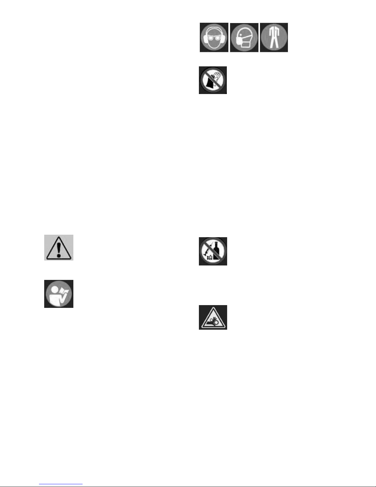
Always wear the approved working outfit:
- safety goggles
- ear protection
- dust protection
Do not wear gloves while operating this machine.
Install the machine so that there is sufficient space for
safe operation and workpiece handling.
Keep work area well lighted.
The machine is designed to operate in closed rooms
and must be placed stable on firm and levelled table
surface.
Make sure that the power cord does not impede work
and cause people to trip.
Keep the floor around the machine clean and free of
scrap material, oil and grease.
Stay alert, give your work undivided attention.
Use common sense. Do not operate the machine
when you are tired.
Do not operate the machine under the influence of
drugs, alcohol or any medication. Be aware that
medication can change your behaviour.
Keep an ergonomic body position.
Maintain a balanced stance at all times.
Never reach into the machine while it is operating or
running down.
Never leave a running machine unattended. Before
you leave the workplace switch off the machine.
Keep children and visitors a safe distance from the
work area.
Do not operate the electric tool near inflammable
liquids or gases.
Observe the fire fighting and fire alert options, for
example the fire extinguisher operation and place.
Do not use the machine in a dump environment and
do not expose it to rain.
Wood dust is explosive and can also represent a risk
to health.
Dust form some tropical woods in particular, and from
hardwoods like beach and oak, is classified as a
carcinogenic substance.

Always use a suitable dust collection device
Before machining, remove any nails and other foreign
bodies from the workpiece.
Make sure to guide and hold the chisel with both
hands safe and tight during machining.
Work only with well sharpened tools.
Machine only stock which is chucked securely on the
machine, always check before switching the machine
on.
Provide workpieces with centre holes before clamping
between centres.
Work large and unbalanced workpieces at low
spindle speed only.
When sanding, remove the tool rest from the
machine.
Workpieces with cracks may not be used.
Remove the chuck key or dowel pins before turning
the machine on.
Always close the belt cover.
Specifications regarding the maximum or minimum
size of the workpiece must be observed.
Test each set-up by revolving the work by hand to
insure it clears the tool rest and bed. Check setup at
the lowest speed before you increase to the operating
speed.
Do not remove chips and workpiece parts until the
machine is at a standstill.
Never stop work pieces with the hand during run out.
Do not attempt to engage the spindle lock pin until
the spindle has stopped.
Never take measurements on a rotating workpiece.
Do not stand on the machine.
Connection and repair work on the electrical
installation may be carried out by a qualified
electrician only.
Have a damaged or worn power cord replaced
immediately.
Make all machine adjustments or maintenance with
the machine unplugged from the power source.
3.3 Remaining hazards
When using the machine according to regulations
some remaining hazards may still exist.
The rotating workpiece can cause injury.
Workpieces that are inhomogeneous or weak can
explode when being processed due to centrifugal
force.
Only process selected woods without defects.
Unbalanced workpieces can be hazardous.
Injuries can occur when feeding tooling, if tool
supports are not correctly adjusted or if turning tools
are blunt.
Risk of kickback. The tooling is caught by the rotating
workpiece and thrown back to the operator.
Thrown workpieces and workpiece parts can lead to
injury.
Dust and noise can be health hazards. Be sure to
wear personal protection gear such as safety goggles
and dust mask. Use a suitable dust collection system.
The use of incorrect mains supply or a damaged
power cord can lead to injuries caused by electricity.
4. Machine specifications
4.1 Machine description
Fig 1
Fig 1-1

4
A Arm Adjustment Knob
B Upper Arm
C On/ Off Switch
D Variable Speed Control
E Rocker
F Blade Tension Lever
G Blade Clamp
H Upper Blade Guard
I Dust Holes
J Table Slot
K Cast Iron Table
L Dust Port
M Lower Blade Holder
N Tilt Lock Handle
O Tilt Adjust Knob
P Detent Plunger
Q Tilt Angle Scale
R Blade Rack
S Leveling Foot
T Hold-down
U Blade Nozzle
V Arm Lift Retension Screw
W Magnetic On/ Off Switch
X Motor
4.2 Technical data
Horsepower
50W
Phase
single
Voltage
230 V
Cycle
50Hz
Stroke
18mm
Speed variable 400 to 1550
stroke/min
Throat capacity 560mm
Blade type used plain-end (pinless) 130mm
Maximum cutting depth 48 mm
Arm tilt 45 degrees left; 45
degrees right
Table dimensions (LxW) 600 x 322 mm
Table slot width 5mm
Table height from floor, on optional stand
adjustable; 812mm to 965mm
Optional stand footprint (LxW) 711 x 648 mm
Overall dimensions –saw only (LxWxH)
838 x 394 x 445 mm
Overall dimensions –saw on stand (LxWxH)
838 x 648 x 1219 mm
Shipping dimensions –saw only
900mm x 450mm x 480mm
Dust port outside diameter 38mm
Net weight, saw only 31 kg
Net weight, optional stand only 9.8 kg
Overload fuse 5A, 250V
Reference current 5.5 A
Extension cord (H07RN-F): 3x1,5mm²
Installation fuse protection 10A
Isolation class I
4.3 Noise emission
Acoustic pressure level (EN ISO 11202):
Idling LpA 72,5 dB(A)
In operation LpA 78,4 dB(A)
The specified values are emission levels and are not
necessarily to be seen as safe operating levels.
As workplace conditions vary, this information is
intended to allow the user to make a better estimation
of the hazards and risks involved only.
4.4 Content of delivery
1 x Scroll saw
4 x Leveling feet with hex nuts
2 x Lower blade holders
1 x Dust port
1 x Blade rack
5 x Blades, skip type
4 x Rubber washer –(HP5)
Stand ((JET Option # 727200S)
Refer to Figure 8, (5.3 Mounting to bench or stand)
2 x Long top braces –(#3)
2 x Short top braces –(#4)
2 x Short bottom braces –(#7)
2 x Long bottom braces –(#8)
4 x Legs –(#5)
4 x Leg extensions –(#10)
Hardware package (see Figure 2-1); contains:
4 x Hex cap screws 5/16x1 –(HP1)
24 x Carriage bolts 5/16x1/2 –(HP2)
32 x Flat washers 5/16 –(HP3)
28 x Hex nuts 5/16 –(HP4)
Fig 2

Fig 2-1
5. Transport and start up
5.1 Transport and installation
The machine is designed to operate in closed rooms
and must be placed stable on firm and levelled
surface.
For safety reasons, the machine must be bolted to
the work bench or to the optional leg stand.
The base has four 9.5mm through hole (Fig 3).Four
3/8-16 UNC screws, washers and nuts are necessary
with the machine for a possible work bench mount.
Fig 3
For packing reasons the machine is not completely
assembled
5.2 Assembly
If you notice transport damage while unpacking, notify
your supplier immediately. Do not operate the
machine!
Dispose of the packing in an environmentally friendly
manner.
Clean all rust protected surfaces with a mild solvent.
Do NOT lift scroll saw beneath arm (Figure 4) which
may result in damage to linkage system. Always lift
using motor and edge of table (Figure 5).
Figure 4: INCORRECT lifting
Figure 5: correct lifting
5.3 Mounting to bench or stand
The scroll saw should be installed upon a sturdy, flat
surface with all four legs contacting the surface. Do
NOT install with saw partially hanging over edge of
table or workbench.
If scroll saw will not be bolted down to a surface,
install the four foot pads to reduce vibration. See
Figure 6. Lower hex nut may be adjusted for
height. Tighten top hex nut down against saw foot.
Figure 6: leveling foot
The preferred method is to mount the saw directly
to a solid workbench or table, or to the optional
JET stand. If mounting to a workbench, use a pad
(provided rubber washers) between saw and bench
to minimize vibration. See Figure 7.

6
Figure 7: bench mounting (fasteners not
included)
If a non-permanent method is preferred, an
alternative is to fasten the saw to a thick plywood
board (minimum 19mm), then attach the board to a
table using clamps.
5.4 Assembling stand (optional)
1. Assemble stand pieces, referring to Figure 8.
(Refer to exploded view, if further clarification
is needed.) Only hand-tighten all fasteners at
this time.
2. The leg extensions (#10, Figure 8) can be
adjusted for height.
3. If stand will not be bolted to the floor, install
the leveling feet (shown in Figure 8) that were
included with the scroll saw, onto the bottoms
of the stand leg extensions.
4. Position stand upright on level floor. Push
down on stand assembly to settle it on floor,
then fully tighten all fasteners with 12mm
wrench.
5. Some scrollers prefer to tilt the saw toward
them for convenience. If this is desired, adjust
only the two front leg extensions.
6. Mount scroll saw to stand, using fasteners
shown (also identified in Figure 2-1).
Figure 8: stand assembly (optional accessory)
5.5 Blade storage
The blade rack (Figure 9) can be mounted to either
side of the scroll saw. It contains holes for storage
of blades inside “test tubes” (not provided).
Additionally, four slots provide storage for blades
pre-inserted into a blade holder.
Figure 9: blade storage
5.6 Dust collection
Slide dust port into the slot on underside of table. A
dust collector or shop vacuum can be connected to
the dust port via a 2-1/2-inch hose (not provided).
6. Adjustments
Before making adjustments to saw, push rocker
switch to OFF. Also unplug saw from power if
working around blade area.
6.1 Arm tilt
The table remains stationary, so the operator’s
hands can remain in the same comfortable
position, with no risk of the workpiece sliding off
the table. The arm can be tilted up to 45-degrees
left or right for beveled cuts, which are frequently
used in projects such as marquetry.
Refer to Figure 10.
1. Loosen lock handle (A).
2. Make sure upper guard and blower nozzle
positions will not conflict with table.
3. Rotate handle (B) to desired angle. Preset
stops are available at 90°, 45°, 30° and 22.5°,
left and right. Push detent pin (C) while
rotating handle (B) until pin engages hole.
4. Tighten lock handle (A) and release pin.
Lock handle (A) is adjustable to prevent
obstruction when in angled position: Pull out
handle and rotate on pin, then release, making
sure it reseats on pin.

Figure 10: arm tilt adjustment
6.2 Installing blade
Unplug saw from power source before
removing, installing or adjusting a blade.
1. Switch off saw and unplug.
2. Insert lower blade holder (Figure 11) into hole
in blade rack for leverage, and loosen knob.
3. Slide blade into holder as far as it will go.
Tighten blade holder knob.
Figure 11: installing blade into holder
4. Flip clamping lever (D, Figure 12) toward front
of saw to release guide.
5. Push blade holder into clip (E) while guiding
blade through table slot.
6. Push top end of blade into upper guide (F),
making sure it rests between the contact
points of guide set screws.
7. Flip clamping lever (D) toward rear of saw to
tension blade. Do not over-tension blade; this
can result in blade breakage or premature
wear to clamping surfaces.
Figure 12: installing blade into guides
8. Check that blade teeth point forward and down
toward table.
9. Try moving blade by hand to make sure it is
secure. Pluck the blade with your finger, as
you would a guitar string –it should emit a
clear note if properly tensioned.
TIP: If changing a blade while cutting fretwork, you
may first push blade through pilot hole in
workpiece, then install blade to saw. See Figure
13. This prevents having to raise the arm for the
first cut.
Figure 13: installing blade with workpiece

8
6.3 Adjusting blade tension
If blade refuses to be clamped tightly according to
the above steps, one or both of the following
adjustments may be needed (Figure 14):
Upper clamp spring pressure can be adjusted
by lifting handle (D) to vertical position. Rotate
handle clockwise one turn to increase
pressure, then push handle into clamping
position. Note: Too much handle rotation will
prevent clamping.
Turn set screws (G) with 3mm hex wrench
clockwise to reduce gap between clamping
surfaces.
Figure 14: tension adjustment
Either of the above steps should resolve blade
tension problems. If problem still exists:
Rotate arm adjustment knob (Figure 15)
clockwise by hand. This will raise arm and
apply more tension to blade.
IMPORTANT: Rotating arm adjustment knob
for tension purposes should only be done if
absolutely needed, as it will affect later blade
oscillation settings (sect. 6.7).
Figure 15: arm adjustment knob
6.4 Material hold-down
Refer to Figure 16.
Adjust material hold-down as close to workpiece as
possible without impeding workpiece movement.
For vertical adjustment, Loosen knob (H, Figure
16) and slide hold-down to position. Tighten knob.
For forward/back movement and angling to table,
loosen socket head screw (J) and adjust. Tighten
screw.
Figure 16: hold-down
6.5 Speed control
Refer to Figure 1.
Rotate speed control knob while saw is running –
clockwise to increase blade strokes per minute,
counterclockwise to decrease.
6.6 Squaring blade to table
Refer to Figures 17 and 18.
The blade may get out of alignment with the table
over time, depending upon how often the saw is
used, and frequent use of the tilt mechanism.
Periodically check squareness of blade to table as
follows.
1. Turn off saw, unplug from power source.
2. Make sure blade is fully tensioned.
3. Set blade tilt to “0” (90 degrees).
4. Place a machinists square or other 90-degree
measuring device on table and against blade
(Figure 17). Do not deflect blade by pushing
into it.

Figure 17: inspecting blade squareness
5. If side of blade does not lie flush against
square, first check that the set screws (see G,
Figure 17) protrude evenly into the clamping
area. Adjust if needed.
6. If blade is still not perpendicular, loosen eight
screws on trunnion plates, at front and back of
saw (Figure 18)
7. Nudge trunnion/arm assembly until side of
blade is flush to square.
8. Tighten all screws at front and back.
9. If needed, loosen screw on pointer (K) and
adjust it to zero. Tighten screw.
Figure 18: squaring blade to table
6.7 Adjusting blade oscillation
Refer to Figure 19.
Blade movement can be adjusted to accommodate
different wood stock and types of operations. For
example, for faster, more aggressive cutting the
blade can be adjusted for slight backward
movement on the upstroke, and slight forward
movement into the wood on the downstroke. For
slower, fine detail work and more control,
completely vertical blade movement is often
preferred.
This adjustment is based upon user’s preference;
as the scroller gains experience, he/she will get a
feel for the oscillation that is most efficient for the
work at hand.
1. Turn off saw and unplug.
2. First verify that upper arm is parallel to table
surface (Figure 19). Push arm down, and
measure at front and back of arm; if
measurements are different, rotate arm
adjustment knob (L) until upper arm is parallel.
Figure 19: arm/table parallelism
3. Adjustments to blade oscillation can be subtle;
place a square or block of wood on table and
alongside blade as reference.
4. Loosen screws on motor flange (M, Figure 20)
with 4mm hex wrench. Only loosen screws
enough to allow motor rotation.
5. Turn motor shaft (N, Figure 20) with flat-blade
screwdriver to observe blade motion.
Alternatively, you may turn on saw to slowest
speed to observe blade motion.
Figure 20: blade oscillation

10
6. Slowly rotate entire motor by hand to adjust
oscillation. Clockwise rotation will make blade
movement more aggressive on downstroke.
Counter-clockwise will make blade more
aggressive on upstroke. See Figure 23.
TIP: If more rotation is needed, turn off saw
and install motor mount screws in second set
of holes behind motor flange.
7. When desired oscillation is achieved, securely
tighten motor mount screws (M).
6.8 Arm lift retention
Refer to Figure 21.
If arm will not remain in position after being raised,
loosen hex nut (14mm wrench) and slightly turn
adjustment screw clockwise with flat blade
screwdriver, until arm remains in raised position.
Do not overtighten. Tighten hex nut.
Figure 21: tightening arm lift
6.9 Blower nozzle
Adjust blower nozzle away from operator, and as
close to blade as needed without interfering with
blade or workpiece movement.
7Operations
7.1 General operating tips
1. Always use a clean, sharp blade.
2. Maintain proper posture to avoid strain. Saw
table should be set approximately level with
operator’s elbows.
3. Avoid wrist or finger strain which can occur by
constantly pushing workpiece against table.
Always use hold-down whenever possible.
4. Guide the wood into the blade slowly to
prevent blade breakage.
5. You will achieve best results when cutting
wood less than 1-inch thick. When cutting
stock thicker than 1-inch, guide the stock very
slowly into the blade, taking care not to bend
or twist the blade.
6. Blade should have minimum 3 teeth in contact
with workpiece at all times.
7. Make relief cuts as needed to prevent binding
of blade in workpiece.
8. A blade has a tendency to follow the wood
grain. Be prepared to compensate for this to
achieve accurate cuts.
9. Use caution when sawing round pieces, such
as dowels, which tend to roll while cutting.
10. Keep fingers away from cutting path. Avoid
awkward hand positions or getting fingers
wedged between saw arm and workpiece
when cutting small workpieces.
11. For fretwork, drill all needed pilot holes at the
same time before moving to the scroll saw.
Drill pilot holes as close as possible to
reference lines.
12. As a general rule, select the narrowest blades
recommended for intricate curve cutting, and
widest blades for straight cuts or large curve
cuts.
13. Run saw only at high enough speed to
efficiently do the work. Constant running at
maximum speed is not necessary for most
operations, may reduce control of the cutting
process, and may hasten wear on the saw.
7.2 On/off controls
Main switch ( P,Figure 22): Turn on to activate
magnetic switch.
Then Push on/off switch (Q,Figure 22-1): to ON
position (I); saw will operate. Press switch to OFF
position (O) to stop.
Figure 22

Figure 22-1
7.3 Procedure
1. Install blade appropriate for desired operation.
Make sure blade is properly tensioned, and
teeth point forward and down toward table.
2. Position blower nozzle and hold-down.
For straight cutting or outside curve cutting:
3. Turn on saw and allow blade to reach full
operating speed.
4. Set speed using variable control knob.
5. Hold workpiece firmly against table and feed
workpiece directly into front edge of blade with
steady pressure. See Figures 23 and 24. Do
not use excessive pressure –allow the blade
to do the work. Compensate for blade drift.
Figure 23: straight cutting
Figure 24: outside curve cutting
For fretwork (inside cutting):
7. Drill pilot holes in workpiece just large enough
for blade insertion.
8. Release clamp lever (D, Figure 25) and raise
arm.
9. Guide blade through pilot hole in workpiece.
10. Lower arm and tighten clamp lever (D).
11. Hold workpiece tightly against table and turn
on saw. Set speed using variable control knob.
12. Smoothly guide workpiece into blade, using
light pressure. Avoid coming to a complete
stop while cutting.
Figure 25: fretwork cutting
8.0 User-maintenance
Always unplug scroll saw from
power before performing maintenance. Failure
to comply may result in serious personal injury.
8.1 General maintenance
Clean wood dust from the saw frequently, using a
vacuum or compressed air, or damp cloth. Use a
soft bristle brush for crevices.
Use proper eye and respiratory
protection if using compressed air.

12
Keep the table clean. Periodically apply a light coat
of paste wax or spray protectant to the table to
prevent rust and maintain a smooth surface.
When finished cutting, release blade from upper
clamp to remove unneeded tension on clamp
spring. Remove blade if saw will be stored for
longer periods.
Periodically inspect the prongs of the lower spring
plate (see E, Figure 15). Bend upward slightly if
needed to ensure a firm grip upon lower blade
holder.
8.2 Lubrication
Periodically apply light dabs of grease to front and
rear trunnions (Figure 26) where parts slide against
one another.
Figure 26
Bearings in the drive mechanism are pre-lubricated
and sealed; no further attention is needed for
these.
8.3 Fuse inspection
The scroll saw is equipped with a 5-amp fuse for
overload protection. If the saw stops working,
inspect fuse:
13. Unscrew fuse cap (Figure 27) and pull fuse out
of cap.
14. If fuse has blown, replace it.
15. Install new fuse into cap, then screw cap into
hole.
Figure 27
8.4 Commutator brush inspection
To maintain motor efficiency, inspect the two
carbon brushes every two months, or more
frequently if saw is heavily used. Stalling or loss of
power may be a symptom of worn carbon brushes.
If one brush is worn out, replace both at the same
time.
Continued use of a damaged or
worn brush may result in damage to motor
armature.
1. Unplug saw from power source.
2. Unscrew and remove cap with flat blade
screwdriver. See Figure 28.
3. Gently pry up an edge of the brass clip, until
the spring causes it to disengage from hole.
(Notice orientation of brush as you remove it; it
should be inserted in the same manner;
curvature of brush will match curvature of
motor.)
4. Pull out brush and inspect. Brush should be
replaced if any of the following are discovered:
Brush has worn to about 1/2-inch long.
Signs of crumbling, burning or breaking.
End of brush is rough or pitted.
Abnormal coloration of spring
Broken lead in spring
Collapsed spring
5. Install new brush (or reinstall current brush)
and gently press it all the way into hole until
the brass clip is secured.
6. Install cap.
7. Repeat for other brush.
NOTE: It is recommended that saw be run without
load for several minutes to seat new brushes.
Figure 28
9.0 Blade selection
Refer to Figures 29 and 30.

The following information is general in nature. The
scroller is encouraged to research specific options
to meet project needs. Note that the same
specifications may vary among manufacturers.
A wide array of blades are available for the scroll
saw. Woodworking blade sizes range from #3/0 to
#12.
Here are factors to consider when selecting a
blade:
Type of material to be cut (hardwood,
softwood?).
Thickness of workpiece (thicker pieces will
require larger blades).
Features of workpiece (straight cuts, sweeping
curves or tight fretwork?).
These factors are important because they involve
basic concepts of blade design. There are 5 blade
features that normally vary to meet certain kinds of
sawing requirements. They are:
1. width
2. pitch (number of teeth per inch)
3. tooth set
4. blade material
5. tooth form
9.1 Width
Width is measured from back edge of blade to tip
of tooth. Generally, wider blades are used for
making straight cuts and long curves. Narrow
blades are suited for cuts with tight corners, such
as fretwork. When cutting straight lines with a
narrow blade, the blade may have a tendency to
drift (called “blade lead”).
9.2 Pitch
Pitch is measured in “teeth per inch” (TPI) and can
be constant or variable.
A fine pitch (more teeth per inch) will cut slowly but
more smoothly, and minimize vibration. A coarse
pitch (fewer teeth per inch) will cut faster but more
roughly.
Try to use a blade that will have a minimum of 3
teeth engaged in the workpiece at any given time.
9.3 Set
“Set” refers to the manner in which the blade teeth
are bent or positioned. Bending the teeth creates a
kerf that is wider than the back of the blade. This
helps the operator more easily pivot a workpiece
through curve cuts, and decreases friction between
blade and workpiece on straight cuts. Two
common sets are the straight (or alternating) and
the raker.
Figure 29: blade anatomy
9.4 Material
Blades are manufactured by stamping, milling, or
grinding.
Stamped blades are punched out on a press
from sheet steel. The teeth are given an
alternate set to allow clearance in the kerf.
Milled blades are made by flattening a steel
wire, cutting the teeth through a “milling”
process, then heat-hardening the steel.
Ground blades have high-carbon steel teeth
which tend to hold their sharpness longer, and
provide smooth cuts.
Special styles are also available, such as twist
and spiral blades, which cut from all sides.
Most blades offered are 130mm ( 5 inches) long; if
a longer blade is acquired the end can be snipped
off to accommodate the saw.
Optimally, a blade (and the operator’s technique)
should leave smooth, clean cuts that do not require
sanding, as it is often very difficult to sand inside
cuts after they are made.
Instead of purchasing a wide assortment of styles
from the start, the scroller may find a few carefully-
selected styles will serve most of his or her needs.
The selection can be expanded as the scroller
gains experience.
9.5 Tooth form
Figure 30 shows common blade forms. Tooth form
has an effect on cutting rate.

14
Regular: Standard blade form with evenly spaced
teeth and zero-degree rake angle. Offers clean
cuts at slower feed rates.
Skip Tooth: More space between teeth, for good
chip removal and fast cuts.
Double Tooth: A skip tooth with larger gaps
between tooth sets; good chip removal, fast
cutting.
Reverse Tooth: Prevents underside tear-out,
leaves clean edge.
Spiral: Cuts on all sides without turning workpiece;
limited applications but good for looser fretwork.
Crown Tooth: Cuts on both up and down strokes
for clean, splinter-free edges. Depending on blade
oscillation settings, a crown tooth blade may often
be turned over for a fresh set of cutting teeth.
Figure 30: blade forms
10. Trouble shooting
Motor will not start.
*No electricity-
check mains and fuse.
*Defective switch, motor or cord-
consult an electrician.
Motor will not start: fuses blow or circuit
breaker trips.
* Short circuit in motor or loose connections-
Inspect all connections on motor for loose or shorted
terminals or worn insulation.
Tilting mechanism difficult to move.
*Caked dust or other obstruction in trunnion
assemblies-
Clean trunnion areas and apply light dabs of
grease to contacting parts.
Blades frequently break.
*Incorrect blade tension-
Set proper tension.
*Blade being overworked-
Reduce feed rate.
*Blade twisting in workpiece-
Avoid side pressure on blade. Reduce feed rate.
Excessive vibration.
*Arms/linkage system not tight-
Tighten trunnion lock knob.
11. Environmental protection
Protect the environment.
Your appliance contains valuable materials which can
be recovered or recycled. Please leave it at a
specialized institution.
12. Available accessories
Stock number
727200S
Steel stand

Stock number 727201
Lower Blade Holder (set of 3)
Other manuals for JWSS-22B
2
Table of contents
Other Jet Saw manuals
Popular Saw manuals by other brands

Grizzly
Grizzly EXTREME G0605X owner's manual

Parkside
Parkside KH 3038 SCROLL SAW Operation and safety notes

Bosch
Bosch Professional GSA 1100 E Original instructions

Bartell Global
Bartell Global BSS18H39W owner's manual

Parkside
Parkside PZKS 1500 B2 Operation and safety notes

Makita
Makita LS1011 instruction manual