Expander E2, E4
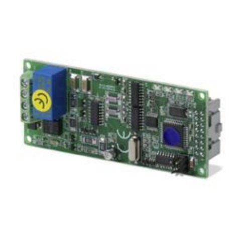
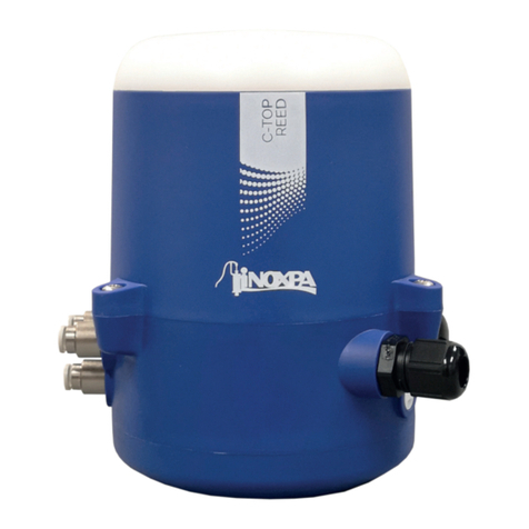
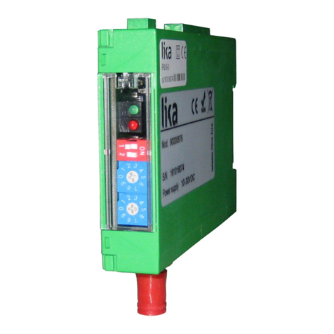
The Expanders E2 and E4 are extension modules of the telemetric system DUPLEX 2,4 GH .
Expander 2 can be extended by up to two telemetric sensors. Expander E4 by up to 4. Thanks to the
Expander properties there exists the possibility to supervise simultaneously data of several telemetric
sensors including the set alerts. The measured data are evaluated by the JETIBOX terminal and the
informations can be transferred by the wireless 2,4 GH DUPLEX system.
Basic Data DUPLEX E2 DUPLEX E4
Dimensions 27 x 14 x 5 mm 36 x 20 x 5 mm
Weight 4 g 7 g
Max. Number of Connected
Telemetric Sensors 2 4
Oprating Temperature - 10 to + 85° C - 10 to + 85° C
Voltage Supply 3,2 – 8,4V 3,2 – 8,4V
Average Current 5 mA 5 mA
Lining up the EXPANDER:
1. The triple core cable with JR plug can be connected directly to the JETIBOX (to the socket
marked Impuls, + - ). Connect the current supply with a voltage of 5-8,4V to the second JETIBOX
input marked (+ - ). This connection mode does not take advantage of wireless data transfer,
measured data are directly shown on the JETIBOX LCD display. Due to the fact that the signal
source is part of the transmitter module which is not available in that case, acoustic alerts are not
possible. They are ownly shown in the LCD display.
2. Plug the triple core cable with JR-plug into the socket of the DUPLEX receiver (marked by Ext.)
on the receiver backside. The Expander receives its current supply via the receiver. In order to
show parameters of the telemetric sensors, connect the JETIBOX to the transmitter module and
switch on the receiver and DUPLEX transmitter.
Lining up of te emetric modu es:
The Expander is provided with sockets for the connection of telemetric sensors marked by (D,+,-). Plug
the JR-plug of the sensor into the Expander input (see sensor manual). In order to improve lucidity of the
picture in the JETIBOX LCD-display we recommend to arrange sensors beginning with expander input 1
and following with connections upwards.
The EXPANDER-Menu:
Parameter adjustments and data readout is carried out with the aid of the JETIBOX terminal. When the
Expander is connected its identification is shown and in the second line of the LCD-display there appears
the second line of the telemetric sensor description, which is plugged into Expander input 1.
With the JETIBOX push buttons N and D (arrows up and down) you may browse through the Expander
inputs. The chosen input is marked by a double bent parenthesis behind the input number, for instance
1}. By pushing the button R (arrow right) you may enter the menu of the chosen sensor and adjust its
parameters and appearance.
There are on y the second ines of the connected sensor menus shown in the EXPANDER menu
together with the identification of the EXPANDER input where the sensor is connected to.
Return from the sensor menu:
- press the button N (arrow up) for a fairly long time
- if you are located in the basic menu of the sensor, a short tipp on button L (arrow left) reveals
in the first line the sensor identification and in the second line actual data (for example MUI 30 ;
14,2V 7,8A).
The input marked for instance by 4}… means, that there is no equipment connected to this input or the
eqipment is not compatible.
1
