Sony HDCU-1700 User manual

OPERATION MANUAL [English]
1st Edition (Revised 4)
HD CAMERA CONTROL UNIT
HDCU1700
4K/HDR PROCESSOR BOARD
HKCU2040
3G/HD SDI OUTPUT EXPANSION UNIT
HKCU2007
SD ENCODER UNIT
HKCU1001
MULTI INTERFACE UNIT
HKCU1003

2
Table of Contents
Overview .....................................................................3
System Configuration................................................5
Basic System Components ............................................. 5
System Operation Example............................................. 6
Locations and Functions of Parts ............................7
Front Panel...................................................................... 7
Rear Panel ...................................................................... 9
Internal Switches ........................................................... 11
HKCU2040 4K/HDR Processor Board (optional) .......... 11
HKCU2007 3G/HD SDI Output Expansion Unit
(optional) .................................................................... 11
HKCU1001 SD Encoder Unit (optional) ........................ 12
HKCU1003 Multi Interface Unit (optional) ..................... 12
Connections and Settings.......................................15
Fiber Transmission System........................................... 15
4K/HDR output system.................................................. 16
Status Display ..........................................................17
Displaying the Status Screen ........................................ 17
Status Display Screen ................................................... 17
Setup Menu...............................................................21
Changing Menu Item Settings ....................................... 21
Menu Tree ..................................................................... 23
Menu List....................................................................... 26
Appendix...................................................................39
Notes on Use................................................................. 39
Error Messages ............................................................. 39
Specifications...........................................................40
HDCU1700 .................................................................... 40
HKCU2040 (optional) .................................................... 41
HKCU2007 (optional) .................................................... 41
HKCU1001 (optional) .................................................... 42
HKCU1003 (optional) .................................................... 42

3
Overview
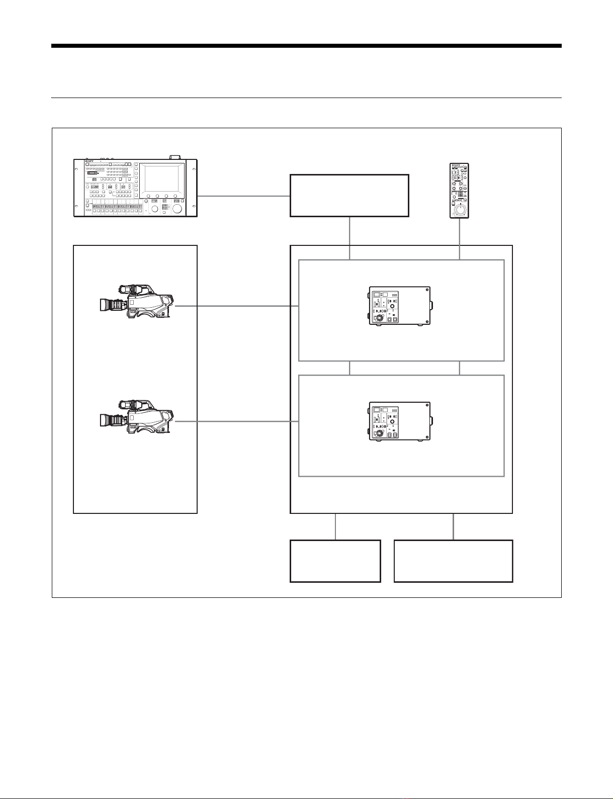
The HDCU1700 Camera Control Unit is connected to a Sony
HDC1700 high-definition video camera. It carries out signal
processing and provides an interface for external equipment.
This unit may be combined with an MSU-1000 series Master
Setup Unit (optional) or an RCP-1000 series Remote Control
Panel (optional) to form a camera control system. Further, a
system capable of controlling multiple video cameras can be
configured by adding a CNU-700 Camera Command Network
Unit.
The HDCU1700 has the following major features.
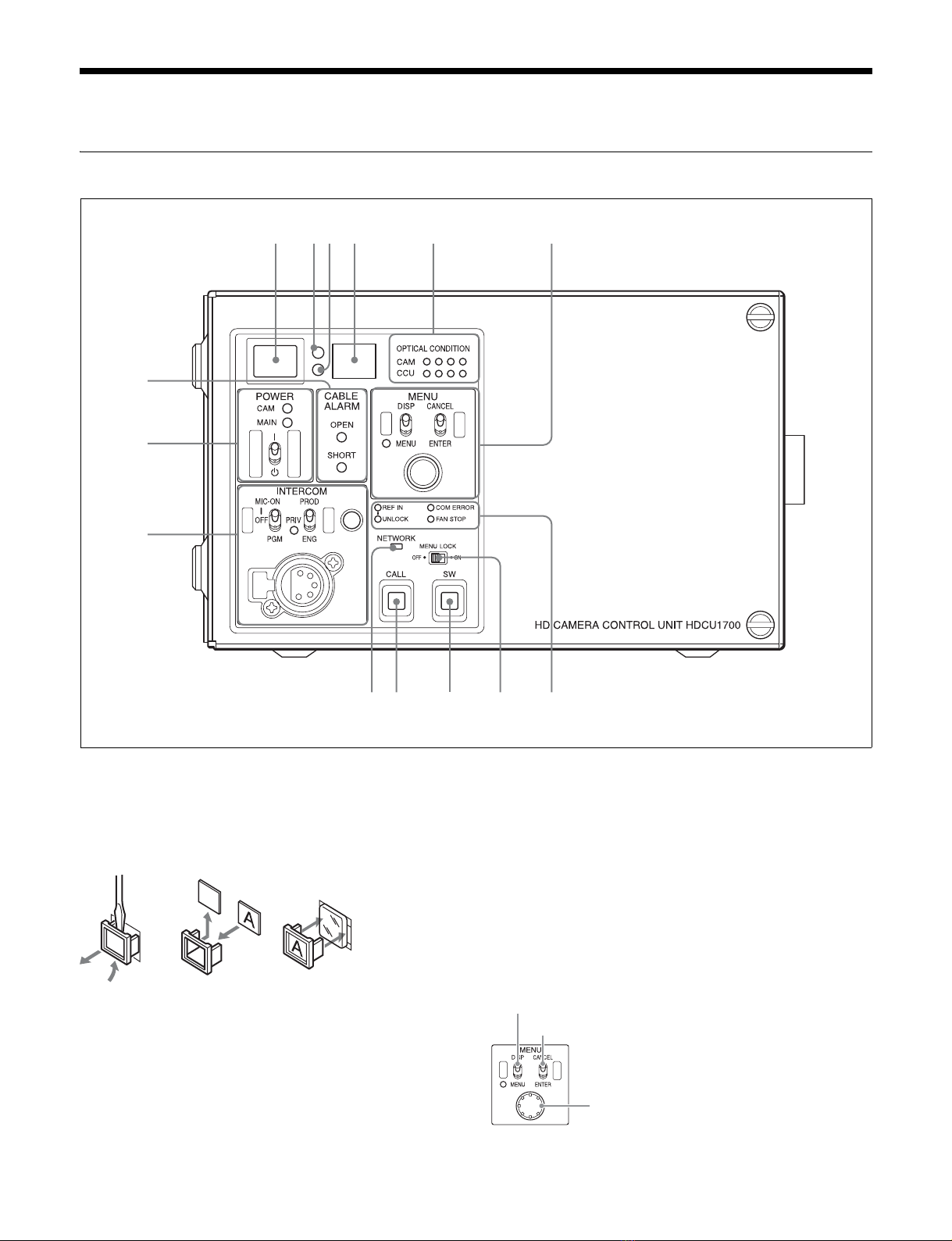
Front panel for increased usefulness
The HDCU1700 features a design that places menu operation
switches and status LEDs related to optical transmission, etc.,
on the front panel. These were moved from under the cover of
the HDCU1000/1500’s front panel, providing even greater
convenience.
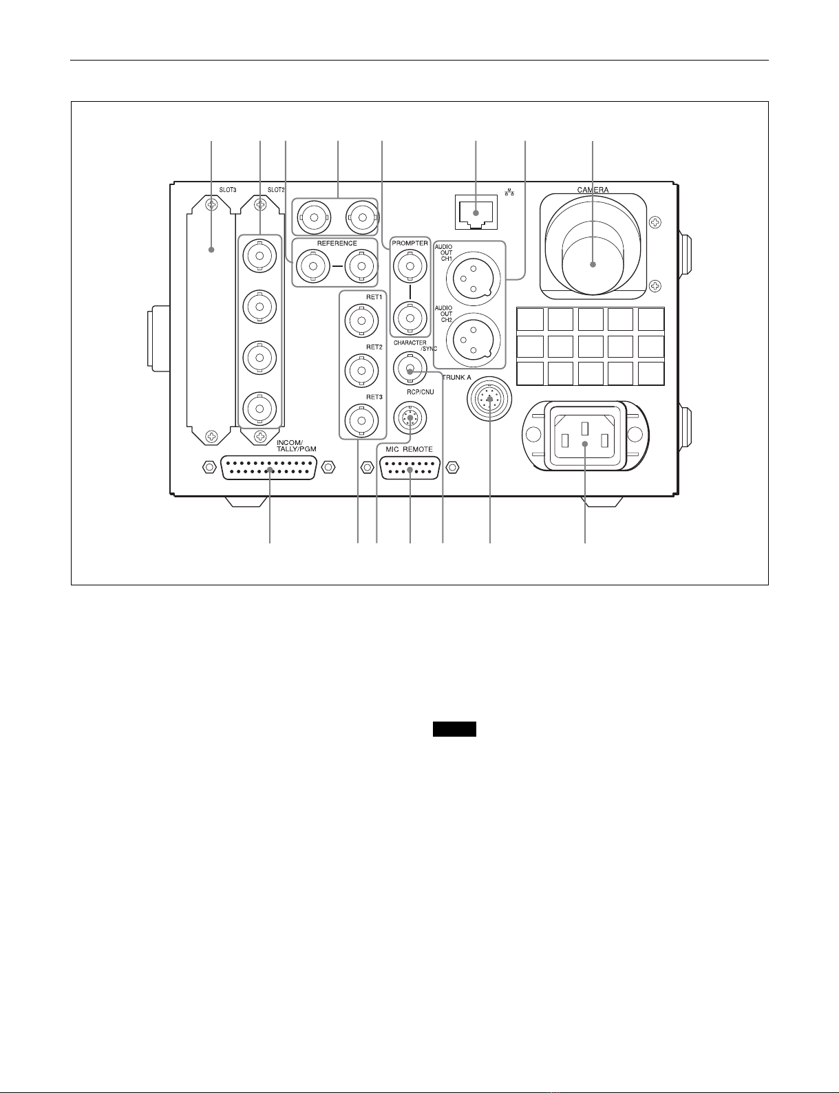
Multiple video inputs and outputs
The HDCU1700 features the following standard-feature signal
input/output ports.
• Four SDI outputs (HD/SD switchable outputs)
• Three HD-SDI/SD-SDI/SD analog return inputs
• One teleprompter input
In addition, a variety of input/output interfaces are offered via
optional installable boards.
HKCU2040 4K/HDR Processor Board
This provides functions, such as changing the resolution from
the HD camera signal to 4K video, or video processing with the
high dynamic range (HDR)*1. 4K video can be output via the
Multi-Link 3G-SDI signal or 12G-SDI signal*2, or HD video can
be output via the 3G-SDI signal or HD-SDI signal.
*1The high dynamic range (HDR) function will be supported
by the software version V3.10 or higher.
*212G-SDI output will be supported by the software version
V3.30 or higher.
HKCU2007 3G/HD SDI Output Expansion Unit
This provides four 3G/HD-SDI outputs.
Installing this board makes it possible to output up to four 3G/
HD-SDI signals.
HKCU1001 SD Encoder Unit
Installing this board makes it possible to output SD analog
composite signals (NTSC/PAL), SD picture monitor signals
and SD waveform monitor signals.
HKCU1003 Multi Interface Unit
This board consists of 3 types of VDA boards, and makes the
following input/output signals possible:
• Frame reference input and output to lock 2-3 pull-down
sequence
• SD analog component signal (RGB or Y/R-Y/B-Y) or SD
analog composite signal output
• SD analog composite signal (NTSC/PAL) output, SD picture
monitor signal output, SD waveform monitor signal output
External reference signals
The HDCU1700 can be locked to an external reference signal.
Either an HD tri-level sync signal or an SD sync (black burst)
signal may be used as the reference signal.
Built-in down converter
When the system is operating at a 59.94/50 Hz field
frequency, HD signals can be converted to SD component SDI
signals using the down converter. The output signal aspect
ratio may be set to 4:3 edge crop, 16:9 squeeze, or letter box.
The down converter has image enhancement, gamma control,
and matrix ON/OFF features, and can be controlled externally.
Built-in simplified up converter
The HDCU1700 has a simplified up converter to allow
monitoring of SD signal return video using an HD viewfinder.
The aspect ratio of the return video signal may be set to 4:3
edge crop, 16:9 squeeze, or letter box.
Digital Optical Transfer
The HDCU1700 may be connected to a camera using an
optical fiber cable (two single-mode optical fiber lines, two
power lines and two control lines) for the transmission of digital
video, audio, and control signals. By connecting together
optical fiber cables, signals may be transmitted up to a
maximum of 2,000 meters (6,600 feet). The maximum length
of the cable supplying power varies with the camera system
configuration and with the type of optical fiber cable.
The HDCU1700 supports standard digital optical transfer, and
when used with an HDC1700 camera, can support 1080/50I,
59.94I recording and more via just one optical cable.
Safety-oriented power supply
The HDCU1700 is designed for safety. When the power is
turned on, a low voltage is supplied at first. Only after it has
been verified that an appropriate camera is attached, the
normal 180 V DC power supply is activated. The power is not
supplied unless a camera is connected via an optoelectric
cable.
Also, the HDCU1700 is equipped with an alarm indicator to
warn of open or short circuits in the cable.
Wide range of audio functions
This unit has connectors for two-channel analog audio outputs
and a program audio input. Further, the HDCU1700 can use
an intercom system with two independent channels, and
supports four-wire and RTS/Clear-Com intercom systems.
For information on support for RTS/Clear-Com systems,
contact a Sony service or sales representative.
Remote control
The level and phases of this unit’s output signals can be
controlled remotely by an MSU-1000 series Master Setup
Unit.

4
Microphone volume control
The camera’s microphone volume can be controlled via the
MIC REMOTE connector, MSU, or RCP.
Character monitor signal output
The results of the HDCU1700 self-diagnosis and setup menu
can be obtained with a text display by character signal output.
Rack mountable
This unit may be installed in a standard EIA 19-inch rack (three
units high). (The HDCU1700 needs the RMM-301 Rack Mount
Adaptor (optional).)
Plug-in unit configuration
Internal printed circuit boards are designed for easy plug-in
and removal, which makes it easy to inspect and maintain the
unit.

5
System Configuration
Basic System Components
Camera
HDC1700 HD Color Video
Camera
+
HDVF-EL20/EL30
HD Electronic Viewfinder
Optical fiber cable
Program audio
MSU-1000 series Master Setup Unit
Camera Control Unit
Intercom system
HDCU1700
HD Camera Control Unit
RCP-1000 series
Remote Control Panel
LAN cable Hub
LAN cable
Camera
HDC1700 HD Color Video
Camera
+
HDVF-EL20/EL30
HD Electronic Viewfinder
Optical fiber cable
Camera Control Unit
HDCU1700
HD Camera Control Unit

6
System Operation Example
HDC1700
HDC1700
MSU-1000 series
RCP-1000 series
HD-SDI
HD-SDI
HDCU1700
HDCU1700
Image monitor
Video monitor
LCD monitor
LAN cable
LAN cable
Hub
CCA-5 cable
CCA-5 cable

7
Locations and Functions of Parts
Front Panel
aRed tally indicator
Lights in red when this unit receives a red tally signal. When
the CALL button on the MSU-1000 series Master Setup Unit,
RCP-1000 series Remote Control Panel, etc., is pressed, this
indicator will go out if previously lit, and light up if previously
off. You can attach the supplied number plate here.
bYellow tally indicator
Lights in yellow when this unit receives a yellow tally signal.
cGreen tally indicator
Lights in green when this unit receives a green tally signal.
dCCU number display
The camera number set via the CCU menu is displayed.
eOptical signal reception status indicator
This indicates the camera and CCU’s optical signal reception
status when performing optical transmissions.
When the two lamps on the right (green) are lighted:
Reception status is excellent.
When the second lamp from the right (green) is lighted:
Reception status is good.
When the second lamp from the left (yellow) is lighted:
Reception status is low.
When the lamp on the left (red) is lighted: Reception status
is at the lowest level.
fMENU control block
8
9
qa
24
7
qs
13
qd qf
65
0
DISP/MENU (display/menu) lever and indicator
CANCEL/ENTER lever
CONTROL knob

8
• DISP/MENU (display/menu) lever and indicator
Selects the status display or setup menu display. In setup
menu mode, the indicator turns on.
• CANCEL/ENTER lever
In setup menu mode, used to cancel and enter settings.
• CONTROL knob (rotary encoder)
In status screen mode, used to change the displayed page. In
setup menu mode, used to move the cursor on a page and to
change menu settings. Pressing the CONTROL knob
performs the same function as setting the CANCEL/ENTER
lever to the ENTER position.
gCABLE ALARM indicators
OPEN (red): Lights in red when a camera isn’t connected to
the CAMERA connector on the rear panel of this unit via
an optical fiber cable. Flashes when the connection
status of an optical fiber cable is bad.
SHORT (red): Lights in red when the power supply cord of an
optical fiber cable is short to external, or two power
supply cords are short. Power isn’t input to the camera
when this indicator lights.
hPOWER switch and indicators
Turns the entire system on and off, including this unit, the
video camera, and the RCP-1000 series Remote Control
Panel connected to the REMOTE connector of this unit. The
MAIN indicator and the CAM indicator light when the power
switch is turned on. Pressing the CAM PW button of the
master setup unit and the remote control panel turns off the
video camera only, and only the CAM indicator turns off.
Note
In order for the power supply to supply the unit with the
necessary power to start up, energy is consumed even when
this switch is set to OFF.
iINTERCOM audio input/output and control block
• MIC/PGM (microphone/program) switch
ON: Turns the headset microphone on.
OFF: Turns the headset microphone off.
PGM: Selects program audio output. In this mode, the
INTERCOM knob adjusts the headset program audio
level.
• INTERCOM (intercom select) switch
Selects the intercom signal input/output connection source for
the INTERCOM connector on the front panel.
PROD: Connects the producer line.
PRIV: Blocks the connection to the producer line or engineer
line, allowing private intercom talk between the CCU and
the camera.
ENG: Connects the engineer line.
• PRIV (Private) indicator
Lights when the intercom is in private mode.
• INTERCOM (intercom adjustment) knob
Adjusts the receiver audio level of the intercom.
• INTERCOM connector (XLR 5-pin)
Connects the intercom headset.
To use a headset with a plug other than an XLR 5-pin plug,
consult a Sony service or sales representative.
jNetwork indicator
Displays the network system connection status.
On: When CNS SETTING in the NETWORK SETTING menu
is set to either BRIDGE or MCS, this indicates that
external control equipment (MSU-1000/1500 Master
Setup Unit, RCP-1000-series Remote Control Panel, or
other device) is connected.
Flashing: When CNS SETTING in the NETWORK SETTING
menu is set to either BRIDGE or MCS, this indicates a
connection problem with the external control equipment
(MSU-1000/1500 Master Setup Unit, RCP-1000-series
Remote Control Panel, or other device).
Off: When CNS SETTING in the NETWORK SETTING menu
is set to either BRIDGE or MCS, this indicates that a LAN
cable is not connected or that the network system
connection parameters have not been set.
When the CNS SETTING in the NETWORK SETTING
menu is set to LEGACY, this remains turned off.
kCall button
When pressed, this outputs a call signal to the camera and
external control device (the RCP-1000 series, etc.) that are
connected to this unit. Use this when you want to call and
speak with the camera operator or external control device
operator via intercom.
lMenu lock switch
This locks out operation of the front panel menu operation
area.
mAssignable button
You can set a function for this button via the CCU menu.
nStatus display indicator
REF IN (Green): REFERENCE is being input.
UNLOCK (Red): The input REFERENCE is not locked.
COM ERROR (Red): There is a communication failure with
the camera or other external control equipment (such as
the RCP-1000 series Remote Control Panel).
FAN STOP (Red): The power fan is stopped.
MIC/PGM (microphone/program) switch
INTERCOM (intercom select) switch
INTERCOM (intercom adjustment) knob
INTERCOM connector (XLR 5-pin)

9
Rear Panel
aExpansion slots
For installation of an optional HKCU2007 3G/HD SDI Output
Expansion Unit, HKCU1001 SD Encoder Unit, or HKCU1003
Multi Interface Unit.
For details on installation, contact a Sony service or sales
representative.
bHD/SD SDI OUTPUT (SDI output connectors) area
(BNC-type)
The signal from the video camera may be output as two HD-
SDI signals or two SD-SDI signals. The signals output from the
OUTPUT3 and OUTPUT4 connectors can be superimposed
character and marker signals.
Signals of the same format are output from the SDI 1 and SDI
2 connectors; similarly, signals of another format can be
output from the SDI 3 and SDI 4 connectors.
For details on settings, contact a Sony service or sales
representative.
When you exchange this slot with the optional HKCU2040 4K/
HDR Processor Board, the number of 4K output increases by
one or HD output increases by four.
cREFERENCE connectors (BNC-type)
Input an HD tri-level reference sync signal or SD reference
sync signal (black burst signal, or black burst signal with 10
Field ID) to either of the two connectors.
The input signal is output from the other connector as is (loop-
through output). If loop-through output is not used, terminate
the unused connector at 75 ohms.
The type of reference signal is selected using the setup menu,
or using the MSU-1000 series Master Setup Unit.
For details on the setup menu, contact a Sony service or sales
representative.
Note
To use the VBS signal of the HKCU1001 SD Encoder Unit or
the HKCU1003 Multi Interface Unit (when SC phase lock is
required), use an SD reference sync signal (black burst
signal).
When black burst signal with 10 Field ID is input, REF 10F BB
of OTHERS (C21) must be set to ON.
dSPARE connector (BNC-type)
Reserved for future use.
ePROMPTER (tele-prompter) connectors (BNC-type)
Input a teleprompter signal to either of the two connectors. The
input signal is output from the other connector as is (loop-
through output). If loop-through output is not used, terminate
the unused connector at 75 ohms. If the signal used is a 1.0
Vp-p, 75-ohm signal, it may be output from the PROMPTER
OUT connector of the video camera with a frequency
bandwidth of 5 MHz, regardless of signal format.
78
9
24 6
0
13
qa qs
5
qd qgqf

10
RET4 (return video input 4)
When required, either of the PROMPTER connectors can be
assigned for the fourth return video input, exclusively for
analog VBS signals.
For details on settings, contact a Sony service or sales
representative.
f(LAN) connector (RJ-45 8-pin)
For LAN connection. Connect a LAN HUB (10BASE-T/
100BASE-TX), using a LAN cable (shielded type of category 5
or more).
gAUDIO OUT CH1, CH2 (audio output 1, 2) connectors
(XLR 3-pin)
Used for output of the audio signal to the AUDIO IN
connectors of the video camera.
hCAMERA connector (optical fiber connector)
Used to connect a video camera, using an optical fiber cable.
All video camera signals, including power supply, control,
video, and audio, are sent and received over one optical fiber
cable.
Note
Dust on the connection surface of the optical fiber cable may
result in transmission errors. When not connected, always
cover the end of the connector with the supplied cap.
iINTERCOM/TALLY/PGM (intercom/tally/program
audio) connector (D-sub 25-pin)
Used for input and output of intercom, tally, and program audio
signals. Connect to the intercom/tally/program audio
connector of the intercom system.
Flag function: 10-pin is assigned for the output pin of the Flag
function.
jRET1, RET2, RET3 (return video input 1, 2, 3)
connectors (BNC-type)
• Three different return video input signals may be received
independently.
• The selection of the return video input signal is made by the
return video switch of the video camera.
• The input signal may be set to HD-SDI, SD-SDI, or analog
VBS, using the setup menu, or using the MSU-1000 series
Master Setup Unit.
For details on the setup menu, contact a Sony service or sales
representative.
Refer also to the Master Setup Unit manual.
kRCP/CNU connector (round 8-pin)
Used to connect to an MSU-1000 series Master Setup Unit,
CNU-700 Camera Command Network Unit, or RCP-1000
series Remote Control Panel via a CCA-5 Connection Cable.
Control signals are sent and received via this connector. When
using an RCP-1000 series unit, power is also supplied.
lMIC REMOTE (microphone remote) connector (D-sub
15-pin)
Using this connector, the video camera’s microphone input
level may be set by external equipment such as an audio
mixer, in five level (–60, –50, –40, –30, and –20 dB). When
shooting, set the volume to a level appropriate for the audio
conditions. This connector also outputs red, yellow and green
tally signals.
When DSUB-15 in the CCU CONFIGURATION menu is set to
WF REMOTE and an MSU-1000 series Master Setup Unit or
an RCP-1000 series Remote Control Panel is used to
remotely control a waveform monitor display, use a connector
that is compatible with recall-type waveform monitors. On the
recall-type waveform monitor, set/preset the display mode to
waveform monitor, and then select (recall) that mode
externally.
The microphone input level may also be set using the setup
menu. For details on the setup menu, contact a Sony service
or sales representative.
mCHARACTER/SYNC connector (BNC-type)
Outputs the self-diagnostic results or the setup menu as an SD
monochrome analog video signal.
When CHARA/SYNC in the CCU CONFIGURATION menu is
set to SYNC, this can also be used as a SYNC connector.
SD composite sync or an HD3 synchronous signal will be
output from the internal sync signal generator. (The default is
set to SD composite sync.)
For details on signal selection, contact a Sony service or sales
representative.
nTRUNK A connector (round 12-pin)
Used to connect to the CCU connector on a video camera via
an RS-232C or RS-422A interface. Communication with up to
two channels is available.
oAC IN (AC power input) connector
Use the specified AC power cord to connect to an AC power
supply. The AC power cord can be secured to this unit, using
the plug holder (optional).

11
Internal Switches
Note
To reduce the risk of electric shock, fire or injury, do not open
the cabinet. To adjust the internal settings, refer to qualified
service personnel.
The following switches are located inside the unit, behind the
front panel:
aInternal main power switch
When an abnormality has occurred, and power cannot be cut
off with the POWER switch on the front panel, you may turn off
the unit using the internal main power switch. When the switch
is set to OFF, setting the POWER switch on the front panel to
ON doesn’t turn on the unit.
HKCU2040 4K/HDR Processor Board
(optional)
Note
To reduce the risk of electric shock, fire or injury, do not open
the cabinet. To adjust the internal settings, refer to qualified
service personnel.
The HKCU2040 4K/HDR Processor Board consists of a DPR
front board, a DIF rear board and an HIF rear board.
The HIF-57 board is not used in this unit. The number of the
Quad Link 3G-SDI signal increases by one or four 12G-SDI
signals as 4K outputs, or four HD outputs.
For details on installation, contact a Sony service or sales
representative.
DIF-247 Board
aSDI OUT 1, 2, 3, 4 (3G/HD serial digital interface output
1-4) connectors (BNC-type)
One Quad Link 3G-SDI signal or four 12G-SDI signals can be
selected as 4K output when the camera is set to 1080P(4K/
HDR). Four 3G-SDI or HD-SDI signals may be output when
camera is set to others.
HIF-57 Board (Not used in this unit)
aSDI OUT 1, 2, 3, 4 (3G/HD serial digital interface output
1-4) connectors (BNC-type)
The signal from the video camera may be output as four 3G-
SDI or HD-SDI signals.
HKCU2007 3G/HD SDI Output
Expansion Unit (optional)
Note
To reduce the risk of electric shock, fire or injury, do not open
the cabinet. To adjust the internal settings, refer to qualified
service personnel.
The HKCU2007 3G/HD SDI Output Expansion Unit consists of
a DRX front board and an HIF rear board.
1
1
3
2
4
SDI OUT
1
1
3
2
4
SDI OUT
1

12
When these boards are installed in the front and rear
expansion slots of the unit, the number of 3G/HD-SDI output
connectors increases by four. These can also be installed on
HDCU1700’s expansion slots.
The format of SDI signals output via each upper/lower pair of
connectors on the HIF board can be set.
For details on installation, contact a Sony service or sales
representative.
HIF-57 Board
aSDI OUT 1, 2, 3, 4 (HD serial digital interface output 1-
4) connectors (BNC-type)
The signal from the video camera may be output as four 3G/
HD-SDI signals.
HKCU1001 SD Encoder Unit (optional)
Note
To reduce the risk of electric shock, fire or injury, do not open
the cabinet. To adjust the internal settings, refer to qualified
service personnel.
The HKCU1001 consists of an EN-A front board and a VDA-A
rear board.
When these boards are installed in the front and rear
expansion slots of the unit, the unit outputs SD composite
signals, waveform monitor output signals, and picture monitor
output signals through the VDA-A board’s connectors.
For details on installation, contact a Sony service or sales
representative.
VDA-A Board
aVBS 1, 2 (composite video output 1, 2) connectors
(BNC-type)
The signal from the video camera may be output as two
analog composite signals.
bPIX OUT (picture monitor output) connector (BNC-
type)
Outputs the video signal for a picture monitor selected with the
PICTURE MONITOR button of an RCP-1000 series Remote
Control Panel or MSU-1000 series Master Setup Unit.
Character signals or marker signals can be superimposed on
the video signal output through this connector.
For details on these operations, refer to the Master Setup Unit
or Remote Control Panel manuals.
cWF OUT (waveform monitor output) connector (BNC-
type)
Outputs the video signal for a waveform monitor selected with
the WF MONITOR button of an RCP-1000 series Remote
Control Panel or MSU-1000 series Master Setup Unit.
For details on these operations, refer to the Master Setup Unit
or Remote Control Panel manuals.
HKCU1003 Multi Interface Unit
(optional)
Note
To reduce the risk of electric shock, fire or injury, do not open
the cabinet. To adjust the internal settings, refer to qualified
service personnel.
The HKCU1003 consists of an EN-B front board and three
VDA rear boards (A/B/C).
When the EN-B board and one of the VDA rear boards are
installed in the front and rear expansion slots of the unit, the
unit inputs or outputs the following signals.
• Outputs SD composite signals, waveform monitor output
signals, and picture monitor output signals through a VDA-
A board.
• Inputs/outputs the frame sequence signal when operating a
24P system through a VDA-B board.
1
3
2
4
SDI OUT
1
VDA-A
1
2
PIX
OUT
WF
OUT
VBS
1
2
3

13
• Outputs analog component signals or analog composite
signals through a VDA-C board.
When you use either the VDA-A board or the VDA-B board,
insert the EN-B board in the corresponding expansion slot on
the front of the HDCU1700. When either the VDA-A board or
the VDA-B board is installed, you can insert the VDA-C board
in an expansion slot on the rear panel of the HDCU1700.
Don't insert any board in the corresponding expansion slot on
the front of the HDCU1700.
For details on installation, contact a Sony service or sales
representative.
VDA-A Board
aVBS 1, 2 (composite video output 1, 2) connectors
(BNC-type)
The signal from the video camera may be output as two
analog composite signals.
bPIX OUT (picture monitor output) connector (BNC-
type)
Outputs the video signal for a picture monitor selected with the
PICTURE MONITOR button of an RCP-1000 series Remote
Control Panel or MSU-1000 series Master Setup Unit.
Character signals or marker signals can be superimposed on
the video signal output through this connector.
For details on these operations, refer to the Master Setup Unit
or Remote Control Panel manuals.
cWF OUT (waveform monitor output) connector (BNC-
type)
Outputs the video signal for a waveform monitor selected with
the WF MONITOR button of an RCP-1000 series Remote
Control Panel or MSU-1000 series Master Setup Unit.
For details on these operations, refer to the Master Setup Unit
or Remote Control Panel manuals.
VDA-B Board
aFRAME REF IN, OUT (frame reference input/output)
connectors (BNC-type)
Input an HD tri-level reference sync signal or SD reference
sync signal (black burst signal) for the sequence-lock between
the camera control units, to the upper of the two connectors.
The input signal is output from the lower connector as is (loop-
through output).
When not using the OUT connector, terminate it at 75 ohms.
bPIX OUT (picture monitor output) connector (BNC-
type)
Outputs the video signal for a picture monitor selected with the
PICTURE MONITOR button of an RCP-1000 series Remote
Control Panel or MSU-1000 series Master Setup Unit.
For details on these operations, refer to the Master Setup Unit
or Remote Control Panel manuals.
cWF OUT (waveform monitor) connector (BNC-type)
Outputs the video signal for a waveform monitor selected with
the WF MONITOR button of an RCP-1000 series Remote
Control Panel or MSU-1000 series Master Setup Unit.
For details on these operations, refer to the Master Setup Unit
or Remote Control Panel manuals.
VDA-C Board (Not used in this unit)
VDA-A
1
2
PIX
OUT
WF
OUT
VBS
1
2
3
FRAME
REF IN
PIX
OUT
WF
OUT
OUT
VDA-B
1
2
3
VBS
R/R-Y
G/Y
B/B-Y
VDA-C
1
2

14
aVBS (composite video signal output) connector (BNC-
type)
The signal from the video camera may be output as an analog
composite signal.
bR/R-Y, G/Y, B/B-Y (component video signal output)
connectors (BNC-type)
The signal from the video camera may be output as a R/R-Y,
G/Y, B/B-Y component signal or an RGB component signal.

15
Connections and Settings
Fiber Transmission System
The camera and the camera control unit are connected via a
single optical fiber cable, and the optical transmission is
achieved.
Connection example
Settings
Camera control unit
Format: Select 1080/59.94I or 1080/50I.
INCOM
INTERCOM 1
PROD
LEVEL
REAR
FRONT
MIC
ON
OFF ENG
OFF
+48V
MIC
FRONT MIC
PROMPTER
/GEN
LOCK
RET CTRL
AUDIO IN
CH1 CH2
TEST
OUT
SDI
MONI
DC IN 10.5-17V
LINE
OFF
+48V
MIC
AES/EBU
LINE
INCOM
INTERCOM 2
EARPHONE REMOTE
DC OUT
CRANETRACKER
PROD
LEVEL
REAR
FRONT
MIC
ON
OFF ENG
SDI OUT 3
(SLOT2)
SDI OUT 1
(SLOT2)
RET 1-3
PROMPTER
TEST OUT
CCU
CAMERA
REFERENCE
HDC1700
HDCU1700
Optical fiber cable
Prompter source
(VBS)
Prompter/
Floor monitor
VTR Switcher
(HD-SDI)
Monitor
(HD-SDI) Hub
Network cable
BNC cable
(HD-SDI)
Reference signal
MSU-1000/1500
Master Setup Unit
RCP-1500/1501/1530
Remote Control Panel
RET (SD-SDI/HD-SDI)
RET (SD-SDI/HD-SDI)
RET (SD-SDI/HD-SDI)

16
4K/HDR output system
Available only when a slot is installed to the HKCU2040 4K/
HDR Output Processor Board (optional).
Connection example
Settings
Camera
MAINTENANCE menu, <CAM MODE> page:
Set CURRENT to 4K/HDR MODE (DOWNCONV
INVALID).
Camera control unit
Format: Select a format of 1080/59.94P (4K/HDR) or 1080/
50P (4K/HDR).
SYSTEM OPERATION menu, when HDR output is selected.
<4K/HDR> page: Set HDR MODE to LIVE HDR.
<OUTPUT FORMAT> page: Set OETF and COLOR
SPACE of HDR output.
INCOM
INTERCOM 1
PROD
LEVEL
REAR
FRONT
MIC
ON
OFF ENG
OFF
+48V
MIC
FRONT MIC
PROMPTER
/GEN
LOCK
RET CTRL
AUDIO IN
CH1 CH2
TEST
OUT
SDI
MONI
DC IN 10.5-17V
LINE
OFF
+48V
MIC
AES/EBU
LINE
INCOM
INTERCOM 2
EARPHONE REMOTE
DC OUT
CRANETRACKER
PROD
LEVEL
REAR
FRONT
MIC
ON
OFF ENG
PROMPTER
RET 1-3
CCU
CAMERA
REFERENCE
HDC1700
HDCU1700
Optical fiber cable
Prompter source
(VBS)
VTR
Switcher
(3G-SDI Quad
Link)
Monitor
(3G-SDI Quad
Link)
Hub
Network cable
Reference signal
MSU-1000/1500
Master Setup Unit
RCP-1500/1501/1530
Remote Control Panel
RET (SD-SDI/HD-SDI)
RET (SD-SDI/HD-SDI)
RET (SD-SDI/HD-SDI)

17
Status Display
The CCU system status can be monitored using a picture
monitor connected to the PIX output.
For information on monitoring and changing settings, see
“Setup Menu” on page 21.
Displaying the Status Screen
The status screen is controlled using the knob and levers in
the MENU control block on the front panel.
To display the status screen
Set the DISP/MENU lever to the DISP position. The most
recently viewed status screen page is displayed (when first
powered on, the camera settings page is displayed).
Turning the CONTROL knob changes the displayed page.
To exit the status screen display
In status screen display mode, set the DISP/MENU lever to
the DISP position.
Status Display Screen
The following information is displayed on the status display
screen.
• Camera settings
•Systemstatus
• CCU hardware diagnostics
• Camera system diagnostics
• Network diagnostics
• CCU AT board diagnostics
• CCU AVP board diagnostics
• CCU DTX board diagnostics
• Status of the boards inserted in Slot1 to 6
• CCU SDP board diagnostics
• Camera hardware diagnostics
• ROM version information for major components
Camera settings
Page 1
aMaster gain value
Video output signal gain (dB units)
bShutter speed/Clear scan frequency
Shutter speed value. When ECS is on, the clear scan
frequency is displayed.
cShutter/ECS
Shutter/ECS on/off indicator
dCamera auto control information area
Top: Displays the Auto Setup category and execution status
Bottom: Displays the execution item
eND filter
Current ND filter selection
fF-stop value
Lens F-stop value (iris value)
gEX (lens extender)
Lens extender indicator
hD.EX
Digital lens extender indicator
iCC filter
Current CC filter selection
Notes
• Items that are turned off using the <DISPLAY> page
settings of the CCU CONFIGURATION menu are not
displayed.
• A “-” mark is displayed for each item when a camera is not
connected.
Page 2
WHT: White balance R/G/B value
DISP/MENU lever and indicator
CONTROL knob
6
dB
1/2000 OFF
ND:1 F:4.7 EX D.EX CC:B
a
efgh
b
cd
i
6
dB
1/2000 OFF
WHT R: 0 BLK R: 0
G: 0 G: 0
B: 0 B: 0
M:0.0
BLK FLR R: 0
: 0 G: 0
DTL B: 0
: 0 M: 0
ND:1 F:4.7 EX

18
BLK: Black balance R/G/B/Master value
BLK γ:Black gamma value
FLR: Flare balance R/G/B/Master value
DTL: Detail level
Page 3
The setting status for CCU SD signals is displayed.
SD Matrix: Linear matrix correction for down converter output
setting
SD Detail: Contour correction function for down converter
output setting
Note
Items with no explanation are the same as those listed under
“Page 1” in “Camera settings” above.
System status
The model name of the camera connected to the unit, the
format setting, CCU output format setting, external reference
setting and return signal format setting are displayed.
Ref: Reference signal format and lock status
Camera: Model name of the connected camera
HD Main: Return signal format
HD Conv: HD up convert setting status
SD Conv: SD up convert setting status
RET1: Return 1 return format selection status
RET2: Return 2 return format selection status
RET3: Return 3 return format selection status
RET4: Return 4 return format selection status
CCU hardware diagnostics
The name of the board connected to the unit’s front panel and
that board’s self-diagnostic results are displayed.
Slot A to C
Slot 1 to 3
Camera system diagnostics
Page 1
CAMERA: Camera light sensor level
CCU: CCU light sensor level
Fan Power: CCU power supply fan status
Timer: Elapsed time since power-on
CCU Power: CCU power supply type and status
Fiber Cable: Cable length
SerialNo: CCU serial number
Page 2
CAMERA Cable: Camera cable connection status
CAMERA Data: Camera data transmission status
CAMERA Power: Camera power supply status
RCP/CNU Cable: This unit’s REMOTE connector cable
connection status
RCP/CNU Data: Data transmission status from a device
connected to this unit’s REMOTE connector
RCP/CNU Power: Power supply status to a device connected
to this unit’s REMOTE connector
SD Matrix: ON
CC Reduction: ON
SD Detail: ON
Level : 0 Comb : 0
Limit : 0 Lim-w : 0
Crisp : 0 Lim-b : 0
LDKnee: 0 LDGain: 0
Ratio : 0
Freq : 0
Coring: 0 Level : 35
*System Status* 1/17
Ref:HD Lock
Camera :HDC1700(HB)
HD Main:1080/59.94I
HD Conv:-------------
SD Conv:525/59.94I
RET1:1080/59.94I(PsF)
RET2:1080/59.94I(PsF)
RET3:1080/59.94I(PsF)
RET4:1080/59.94I(PsF)
1080/59.94I
** Diagnosis **
A:AT :OK 1:
B:AVP :OK 2:DRX OK
C:DTX :OK 3:RC OK
2/17
*System Diag 1/3* 3/17
Optical Condition
CAMERA OK
CCU OK
Fan Power OK
Timer 56H
CCU Power AC OK
Fiber Cable 100m
SerialNo 00002002
*System Diag 2/3* 4/17
CAMERA Cable Connect
Data OK
Power OK
RCP/CNU Cable Connect
Data OK
Power OK

19
Page 3
Intercom CCU: CCU intercom selection status
Intercom MIC CAMERA ENG: Status for the camera
microphone of the ENG line
(When 1CH is selected via the INTERCOM menu (C07),
---- is displayed.)
Intercom MIC CAMERA PROD: Status for the camera
microphone of the PROD line
CAM MIC Gain: Camera microphone circuit control status
CAM MIC CH1: Camera microphone circuit 1 amp gain status
CAM MIC CH2: Camera microphone circuit 2 amp gain status
Network diagnostics
Page 1
MacAddress: CCU MAC address
Auto Negotiation: Auto negotiation setting status
Auto MDIX: Auto-MDIX setting status
Connect Speed: Connection speed setting status
Duplex Mode: Communication method setting status
MDI/MDIX Select: Communications port wiring configuration
selection status
Link Status: LAN connection status
Page 2
CNS Mode: REMOTE and LAN connectors mode setting
status
CCU No.: CCU number setting status
Master IP Address: Master device IP address
Page 3
IP Addr: CCU IP address setting status
NetMask: CCU subnet mask setting status
Def GW: CCU default gateway setting status
CCU AT board diagnostics
System Frequency: System frequency
CAM Format Setting: Camera format setting status
Reference: Reference signal setting status
Line Delay: HD-SD delay setting status
Power Supply: Status of power supply to the AT board
PLD Version: AT board PLD version
VIF Power: Status of power supply to the VIF board
CCU AVP board diagnostics
Front Power: Status of power supply to the AVP board
PLD Version: AVP board PLD version
ADO Power: Status of power supply to the ADO board
*System Diag 3/3* 5/17
Intercom
CCU System
Intercom MIC
CAMERA ENG ON
PROD OFF
CAM MIC Gain Local
dB
CH1 60
dB
CH2 60
*Network Diag 1/3* 6/17
MacAddress 00014A-xxxxxx
Auto Negotiation: ON
Auto MDIX : ON
Connect Speed : 100M
MDI/MDIX Select : MDIX
Duplex Mode : FULL
Link Status :OK
*Network Diag 2/3* 7/17
CNS Mode : MCS
Master IP Address
192.168. 0.100
CCU No. : (1)
*Network Diag 3/3* 8/17
IP Addr :192.168. 0.101
NetMask :255.255.255. 0
Def GW :192.168. 0.254
*AT Diag* 9/17
System Frequency:1.001
1080/59.94I
Reference :HD Remote
CAM Format Setting
Line Delay :Line(90H)
Power Supply:OK
PLD Version :4.00 Done
VIF Power :OK
*AVP Diag* 10/17
Front Power:OK
PLD Version:1.00 Done
ADO Power :OK

20
CCU DTX board diagnostics
Return Delay: Return delay setting status
Active Ret CH: The selected RET channel
Front Power: Status of power supply to the DTX board
PLD Version: DTX board PLD version
Rear: Name of the board installed in the rear expansion slot
Power: Status of power supply to the board installed in the
rear expansion slot
Status of the board inserted in Slot1
Front: Status of power supply to the board installed in option
slot 1 and the board name
PLD Version: PLD version of the board installed in option slot
1 and the board name
Status of the board inserted in Slot2
When the HKCU2040 board is installed
1 & 2: Output format of Output 1 & 2
3 & 4: Output format of Output 3 & 4
HD CB: The output color bar signal
Status: SDI output status of each connector
Front: Status of power supply to the board installed in option
slot 2 and the board name
PLD Version: PLD version of the board installed in option slot
2 and the board name
Rear: Status of power supply to the rear board and board
name
Note
The items displayed differ depending on board connected to
the expansion slot.
Status of the board inserted in Slot3
The setting status of the board installed in Slot3 (front/rear) is
displayed.
Note
The items displayed differ depending on board connected to
the expansion slot.
CCU SDP board diagnostics
Power: Status of power supply to the SDP board
PLD Version: SDP board PLD version
Camera hardware diagnostics
Displays the camera hardware status.
*DTX Diag* 11/17
Return Delay :F/S
Active Ret CH :2CH
Front Power:OK
PLD Version:1.00 Done
Rear:SDI Power:OK
*Slot1 Diag* 12/17
Front:None
Rear :--------
*Slot2 Diag* 13/17
1&2: 1080/59.94I
3&4:M1080/59.94I
HD CB:BAR 16:9(100%)
SD CB:SMPTE
Front:RC Power:OK
PLD Version:1.00 Done
Rear :HIF Power:OK
*Slot1 Diag* 12/20
1&2: 4K/59.94P(12G)
3&4: 4K/59.94P(12G)
HD CB:BAR 16:9(100%)
SDI Out 1 2 3 4
Status: OK OK OK OK
Front:DPR Power:OK
PLD Version:1.00 Done
2.00
Rear :DIF Power:OK
*Slot3 Diag* 14/17
Front:None Power:OK
PLD Version:1.00 Done
Rear :HIF Power:OK
*SDP Diag* 15/17
Power:OK
PLD Version:1.00 Done
*CAMERA Diag* 16/17
ALL BOARD OK
This manual suits for next models
4
Table of contents
Other Sony Control Unit manuals
Popular Control Unit manuals by other brands

Omron
Omron F3SN-A - user manual

Interpump Group
Interpump Group Pralissoli S1510 operating instructions

CCS
CCS PD3-3024-3-PT Instruction guide

American Standard
American Standard Ultima 6147SM installation instructions

Allen-Bradley
Allen-Bradley ControlLogix DeviceNet 1756-DNB installation instructions

Linx
Linx EVM-915-DTS-FCR Data guide

Emerson
Emerson VS-FL Series instruction manual

1Control
1Control Solo quick guide

Loctite
Loctite 986326 instruction sheet

TE Connectivity
TE Connectivity FORTIS Zd Series Assembly

Furukawa
Furukawa Ofs INVISILIGHT M13AK0007 Assembly instructions

Honeywell
Honeywell Ex-Or CDW12U5 Installation and commissioning instructions