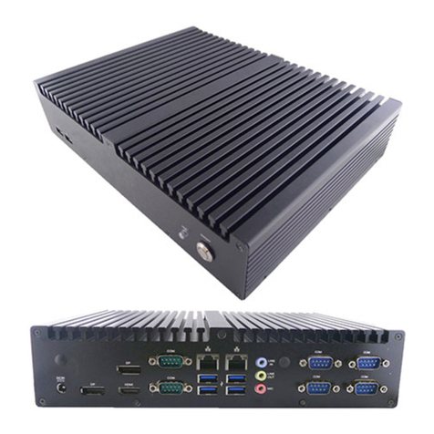
JETWAY HBFMF833W Series User manual

User sManual
NO. G03-FMF833QIG-F
ManualRevision:1.0
Release Date December 17, 2018

i
SafetyPrecautions..............................................................................................................ii
User sNotice.......................................................................................................................iii
Item Checklist......................................................................................................................iii
Environmental Protection Announcement.......................................................................iii
Chapter 1Introduction......................................................................................................1
1-1General Descriptions............................................................................................1
1-2Specifications........................................................................................................1
1-3ProductDiagram...................................................................................................2
1-4I/OOutlets..............................................................................................................3
1-5ConnectorPinDefinition ......................................................................................4
Chapter 2Hardware and Installation................................................................................7
2-1DimensionsandOutlines.....................................................................................7
2-2ToOpentheChassis.............................................................................................8
2-3Jumper Settings....................................................................................................9
2-4Hardware Installation............................................................................................12
2-4-1ToInstallSO-DIMM...................................................................................12
2-4-2ToInstallMini-PCIECard.........................................................................12
2-4-3ToInstallMSATACard.............................................................................14
2-4-4ToInstall2.5 HDD...................................................................................14
2-4-5ToWall MounttheSystem.......................................................................16
Chapter 3Introducing BIOS.............................................................................................17
3-1EnteringSetup......................................................................................................17
3-2BIOSMenu Screen...............................................................................................18
3-3FunctionKeys ......................................................................................................18
3-4GettingHelp..........................................................................................................18
3-5MenuBars ............................................................................................................19
3-6MainMenu ............................................................................................................19
3-7Advanced Menu....................................................................................................20
3-8ChipsetMenu .......................................................................................................28
3-9SecurityMenu ......................................................................................................31
3-10 BootMenu ............................................................................................................31
3-11 Save &ExitMenu .................................................................................................32
TABLEOFCONTENT


ii
SafetyPrecautions
nOperatethe productaccording tothe correctinstallation stepsand withgreatcaretomakesure
safetyand comfortusing experience.Pleaserefertothefollowing safetyinstruction guide toavoid
dangerofelectricshock orfire. Abide bythe previoussafetyinstruction guide touseand maintain
the product and the harddisktomakesureofsafeoperating environment.
nPleasefollowthe instruction manual foroperation guide.
nThe operation humidityforthisproductis5% to80% RH.
nToavoidhigh temperature,pleaseDONOToverload the maximumpowerofthe external power
supplywhilethe systemisconsuminghigh voltage.Beawareofthe maximumtemperature
allowanceof the powersupply.
nSee toitthatthe productisnot working nearthe water.
nAlwaysunplug powercableand otherhardwarecablesfromthe systembeforecleaning.
nApplyonlydryclothforcleansing the product.
nMakesurethat thereisno heat sourcenearbywhen the product isworking.
nMakesurethat the thermal louverof the productisnotblocked.
nMakesuretoremovethe powerplug fromthe productwhenthereisathunderstorm.
nPleaseremovethe powerplug fromthe productwhen you arenotgoing tousethe productfora
long time.
nMakesuretoset up orusethe product on astablesurface.
nMakesurenot todrop the product orstrikeit byanymeans.
nMakesurenot tomovethe productwhen the powerison.
nMakesurenot tostep on the powercablesand othercablesorrest anything inthem..
nBesuretoground yourselftopreventstaticcharge wheninstalling anyinternalcomponents.Usea
grounding wriststrap and placeall electroniccomponentsinanystatic-shielded devices.Most
electroniccomponentsaresensitivetostaticelectricalcharge.
nDisconnectthepowercordfromthePanel PCunitpriortoanyinstallation.Besureboththe
systemand all externaldevicesareturned off. Sudden surgeofpowercouldruinsensitive
components. Makesurethe PanelPCunitisproperlygrounded. unit
nDo notopen the system sback cover.Ifopening thecoverformaintenanceisamust, onlya
trained technician isallowed todo so.Integrated circuitson computerboardsaresensitivetostatic
electricity.Toavoiddamagingchipsfromelectrostaticdischarge,observethe following
precautions:
nBeforehandling aboardorintegratedcircuit,touchanunpainted portion ofthe system
unit chassisforafewseconds.Thiswillhelptodischarge anystaticelectricityon human
body.
nWhenhandling boardsand components,wearagrounding wriststrap availablefrom
most electroniccomponentstores.
nPleasecontact qualified technician formaintenanceorrepair.
nUseonlyaccessoriesand partsthat aremade bythe qualified manufacturer.

iii
User sNotice
Copyrightofthismanualbelongstothe manufacturer.No partofthismanual,including the products
and softwaredescribed initmaybe reproduced,transmitted ortranslated intoanylanguage inany
formorbyanymeanswithout written permission ofthe manufacturer.
Thismanualcontainsallinformation required fortheutilization ofthisproducttomeetthe user s
requirements.But itwillchange,correctatanytimewithoutnotice. Manufacturerprovidesthismanual
“asis”withoutwarrantyofanykind,and will notbeliableforanyindirect, special,incidental or
consequentialdamages(including damagesforloss ofprofit,loss ofbusiness,loss ofuseofdata,
interruption of businessand the like).
Productsand corporatenamesappearing inthismanualmayormaynotbe registered trademarksor
copyrightsof theirrespectivecompanies, and theyareused onlyforidentification orexplanation andto
the owner sbenefit, withoutintenttoinfringe.
Item Checklist
RUsersManual
RDVD
RScrewPack
RPowerCord
RFSP Adapter12V-5A-60W/ LEVEL6
RM12 DC Cable, L=1.2M
EnvironmentalProtection Announcement
Donotdisposethiselectronicdeviceintothe trashwhilediscarding.Tominimize
pollution andensureenvironment protection of motherearth, pleaserecycle.

1
Chapter1
Introduction
1-1General Descriptions
Thankyouforpurchasing HBFMF833W Series, aFanlessEmbedded BoxPC
developed,designedand manufacturedunderleading technicalpowerand
consistent dedication tofine workmanship.
Thesystemhas thefollowingfeatures besides otherbasicfunctions:
lIntel®Skylake/KabylakeU-Processoron board
lSupport 2*SO-DIMM DDR4-2133, upto32GBmemory
lSupport M12 connector
lSupport IP69Kwaterproof anddustprooflevel
lAll-aluminumbody, producedbycastingprocess
lFlexibleI/O forcustomized and mission-criticalprojects
lStainless steelbottomcoverwithstainlesssteelscrewsforoutdooruse
without rust
1-2Specifications
MBModel lJNF833-7X00/ 3.5”SBC
PartNo lHBFMF833W-7X-2L-B
lHBFMF833W-7X-2C-B
BIOS lAMI
CPU/Chipset lIntel®Skylake/KabylakeUProcessor(TDP15W)
*Note: When the systemruns,CPUwill automaticallyadjustitsworking
clock frequency according tochanging workload.
Memory l2*SO-DIMMslotsDDR4-2133MHzup to32GB
Storage l1*2.5”SATA36Gb/sinternaldrivebay
l1*Full-sizemSATA/mini-PCIExpresssharedslot
Network l1*IntelGbE(HBFMF833W-7X-2C-B)
l2*IntelGbE(HBFMF833W-7X-2L-B)
l1*Half-sizemini-PCIEslot (for802.11b/g/n+BT4.0installedin
WIFImodel)
RearPanelI/O HBFMF833W-7X-2C-B HBFMF833W-7X-2L-B
l2*USB2.0
l1*RJ45
l2*COM
l1*HDMI
l2*WIFIAntenna
l1*DC-In
l1*USB3.0
l1*USB2.0
l2*RJ45
l1*COM
l1*HDMI
l2*WIFIAntenna
l1*DC-In
FrontPanelI/O
l1*PowerSW
l1*PowerLED
PowerSource lFSP Adapter/ DC12V-5A-60W
lAC90~240Vinput

2
WaterprooflIP69K
Environment lOperatingTemperature: -20~60°C(undertheconditionofusing
MSATA)
lOperatingTemperature: -20~ 70°C(undertheconditionofusing2.5”
SSD)
*Note: Thetestenvironment isclosed andwindless
lStorageTemperature: -10~70 °C
lHumidity:90%,non-condensing
Dimensions l250(W)x171 (D)x54(H)mm
OSSupport lWindows7,Windows8.1, Windows10,Linux
1-3ProductDiagram
Front:
Rear:

3
1-4I/OOutlets
HBFM833W-7X-2L-B:
HBFM833W-7X-2C-B:
DC
-
IN
RJ
-
45 LAN
USB2.0
USB3.0
COM1:
RS232/422/485
DC
-
IN
USB2.0
RJ
-
45 LAN
USB2.0
COM1:
RS232/422/485
COM2:
RS232
1
2
3
4
5
6
1
2
3
4
5
6

4
1-5ConnectorPinDefinition
(1)ConnectorFunction
Icon NameFunction
PowerButton
Press toturnon/off the system.
HDMI
HDMI Toconnect displaydevicethatsupport HDMI
specification.
DC
DC-inPower
Connector
Forusertoconnect compatiblepoweradapterto
provide powersupplyforthe system.
USB2.0
USB2.0Port
Connector
To
connectUSB keyboard,mouseorotherdevices
compatiblewithUSB 2.0specification.
*Note: 1*USB 2.0connector
for2*USB 2.0expansion
port.
USB3.0
USB3.0Port
Connector To
connectUSB keyboard,mouseorotherdevices
compatiblewithUSB 3.0specification.
LAN
RJ-45 LANPort
Connector ThisconnectorisstandardRJ-45LANjack
forNetwork
connection.
COM1
RS232/422/485
COMPort
Connector
Mainly
forusertoconnectexternalMODEMorother
devicesthat supportsSerialCommunicationsInterface.
COM2
RS232
COMPort
Connector
Mainly
forusertoconnectexternalMODEMorother
devicesthat supportsSerialCommunicationsInterface.

5
(2)I/O ConnectorsPinDefinition
DC:DC-inPowerConnector
The pinassignment forDC-inpowerconnectorislisted asfollows:
PinNO.
Definition
1 DC+9~24V
2 DC+9~24V
3
GND
4 GND
LAN:RJ-45EthernetConnector
The pinassignment forRJ-45 EthernetLANconnectorsarelisted asfollows:
PinNO.
Definition
1 TX_D1+
2 TX_D1-
3 RX_D2+
4 BI_D3+
5 BI_D3-
6 RX_D2-
7 BI_D4+
8 BI_D4-
USB2.0:USB2.0PortConnector
The pinassignment forUSB 2.0portconnectorsarelisted asfollows:
PinNO.
Definition
1 5V
2 D1-
3 D1+
4 GND
5 5V
6 D2-
7 D2+
8 GND
*Note: 1* USB2.0connectorfor2* USB 2.0expansion port.

6
USB3.0:USB3.0PortConnector
The pinassignment forUSB 3.0portconnectorsarelisted asfollows:
PinNO.
Definition
1 5V
2 USB3_RX-
3 USB3_RX+
4 GND
5 USB3_TX-
6 USB3_TX-
7 D-
8 D+
COM1:RS232/422/485COMPortConnector
The pinassignment forRS-232/422/ 485 islisted asfollows:
PinNO.
RS232
*RS422
(optional)
*RS485
(optional)
1
DCD
#
TX- DATA-
2
SIN
TX+ DATA+
3 SOUT RX+ NC
4 DTR# RX- NC
5 DSR# NCNC
6 RTS# NC NC
7 CTS# NC NC
8 RI# NC NC
*Note:COM1portcan function asRS232/422/485 port. InnormalsettingsCOM1
functionsasRS232 port. WithcompatibleCOMcableCOM1can function asRS422
orRS485 port. Useralsoneedstogo toBIOStoset Transmission ModeSelect’
forCOM1(referto Page-23)atfirst, beforeusing specialized cabletoconnect
different pinsof thisport.
COM2:RS232COMPortConnector
The pinassignment forRS-232 islistedasfollows:
PinNO.
RS232
1 DCD#
2 SIN
3 SOUT
4 DTR#
5 DSR#
6 RTS#
7 CTS#
8 RI#

7
Chapter2
Hardwareand Installation
2-1Dimensionand Outlines
*MeasureUnit:mm.

8
2-2 ToOpentheChassis
Useascrewdrivertounscrewthescrewsonthebackcoverthatlockthechassis.
Removethemand put the coveraside toopenthe chassis.
1.
Placethesystemuponaflatoperation
platform withsideupwards. The screwsin
themarkedspotsshouldbe removedwitha
compatiblePhillipsscrewdriver.
2.
Liftup thecovertoopenthechassis.
3.
Removethemarkedscrewsto
dissembletheHDD trayfromthe
systemforfurtherinstallation steps.
4.
Forusertohaveaclearview, we
removetheSATAHDD cable&SATA
power-outcablefromthe systemfor
furtherinstallationsteps.
Notice: It isveryimportantforthe cablesconnected totheiroriginalplacesfornormal
functioning.

9
2-3 JumperSettings
Jumperisasmall component consistingof jumperclipand jumperpins. Install
jumperclipon 2jumperpinstoclosethe pins.And removejumperclipfrom2
jumperpinstoopen thepins. Diagram2-1illustrateshowtosetup ajumper.
JBAT
JPCOM4
J
P1
JPCOM1
JPCOM2
JPCOM3
AT_COPEN
J
P2

10
AT_COPEN(4-pin):ATMode&Case OpenDetection Select
Pin(1-2): ATModeSelect
Pin(3-4):CaseOpenDetection Select
Pin 1&2 ofAT_COPEN
ATModeSelect
1-2Open:ATXMode
Selected(Default);
;
1-2Closed:AT ModeSelected.
Pin1
2
Pin1
2
4
3
3
4
Pin3&4ofAT_COPEN
Case OpenDetection
GND
2
4
3
Pin1
CASE
OPEN
*ATXModeSelected: Press powerbutton topoweron afterpowerinputready;
ATModeSelected: Directlypoweronaspowerinput ready.
Pin(3&4)Closed:WhenCaseopen function pinshorttoGND,theCaseopen
function wasdetected.Whenused,needstoenterBIOSand enable CaseOpen
Detect’function. Inthiscaseif yourcaseisremoved, next timewhen you restart your
computer, amessage will be displayed on screen toinform you of this.
JBAT(4-pin): ClearCMOSRAMSetting &FlashOverride
Pin(1-2): ClearCMOSSettings;
Pin(3-4): FlashOverride.
1-2 Closed:ClearCMOS(OneTouch).
1-2 Open:Normal(Default);
Pin1&2ofJBAT
ClearCMOS
Pin1
2
Pin1
2
Pin1
2
Pin1
Pin 3&4ofJBAT
Flash DescriptorOverride
3-4Open:Normal(Default);
3
4
3-4Closed:DisableFlash
DescriptorSecurity(override).
3
2
4

11
JPCOM1(4-pin): COM1PortPin9FunctionSelect
JPCOM2(4-pin): COM2PortPin9FunctionSelect
JPCOM3(4-pin): COM3PortPin9FunctionSelect
1
3
5
2
4
6
6
4
2
5
3
1
2-4Closed:
Pin9=RING(Default);
3-4Closed:
Pin9= 5V; 6-4Closed:
Pin9=12V.
2
5
3
1
4
6
JPCOM4(4-pin): COM4PortPin9FunctionSelect
1
3
4
6
2
6
4
2
5
3
1
6
4
2
5
3
1
5
2-4Closed:
Pin9=RING(Default);
3-4Closed:
Pin9=5V; 6-4Closed:
Pin9=12V.
JP1(4-pin):LCD VCC Select
1
3
4
6
2
2-4Closed:
LVDSVCC=3.3V;
3
-
4C
losed
:
LVDSVCC=5V; 4-6Closed:
LVDSVCC=
12V.
6
4
2
5
3
1
6
4
2
5
3
1
5
JP2(4-pin):LCD BacklightVCC Select
1
3
4
6
2
2-4Closed:
Backlight=5V;
3
-
4C
losed
:
Backlight=12V; 4-6Closed:
Backlight=DCIN
.
6
4
2
5
3
1
6
4
2
5
3
1
5

12
2-4 HardwareInstallation
Removethe screwsthatlock the back covertothe systemfromthe back sidebefore
hardwareinstallationprocedures(referto 2-2).
2-4-1 ToInstallSO-DIMM
1.
LocatetheSO
-
DIMMmemoryslot
s
on
theboard. Insertthegold-figuresideofthe
compatibleSO-DIMMintotheslotata30
degreeand pressdown.
2.
Seetoit that the
notch
of the modulefit
intothebreakoftheslot;thetwoplasticclips
will automaticallycloseifthememory
moduleisfittedinaproperway.
2-4-2 ToInstall Mini-PCIE Card
Note: Thefollowing photosareforillustration only.Ifyou wishtoinstall compatiblefull-size
card, pleaseinstall it inMini-PCIE/MSATAsharedslot.
1.
Locatethehalf
-
sizeMini
-
PCIEcardslot on
theboard.
2.
Removethemarkedscrewanduseit to
lock half-sizeMini-PCIEcardtotheslot
inlaterinstallation.

13
3.
Insert thegold
-
figuresideofthecompatible
cardintotheslotandpress down.
4.
Lock thecardtotheboardbytightening
up thescrewtothemarkedspot.
5.
Locatetheantennaslotsonthecard.
6.
Press themetalhatonthe endofthe
antenna string tothe antenna sloton the
cardasshown(Ifyouinstall two
antenna, press theleft metalhatof the
leftantennatothe leftslot,the right
metalhat tothe rightslot).
7.
LocatetheWi
-
Fiantenna
connecto
rs
in
therearpanel.
8.
ConnecttheexternalWi
-
Fi
receiver
antennatotheantennaconnectoron
therearpanel.

14
2-4-3 ToInstall MSATACard
1.
Locatethefull
-
sizeMini
-
PCIE/MSATAcard
slot ontheboard.
2.
Removethemarkedscrewanduseit to
lock MSATAcardtotheslot inlater
installation.
3.
Insert thegold
-
figuresideofthecompatible
cardintotheslotandpress down.
4.
Lock thecardtotheboardbytightening
up thescrewtothemarkedspot.
2-4-4 ToInstall2.5 HDD
1.
Removethemarkedscrewsto
dissemble
theHDD trayfromthesystem&unplug
thepre-installedSATAHDD cablefor
furtherinstallationsteps.
2.
The HDD traywithHDD cablelocked to
it with2*screws.

15
3.
PlacecompatibleSATAHDD uponHDD
trayasshowedabove.Plug thisside of
thecabletoSATApower-inconnector
andSATAconnectoroftheharddisk.
4.
TurnovertheHDD trayandfix2.5
HDD
upon HDD traybytightening4*screws
marked incorrespondingspots.
5.
Fix2.5
HDD uponHDD trayby
tightening2*screwsmarkedin
correspondingspots.
6.
Tighteningth
eother2*screwsonthe
othersideoftheHDD tray.
7.
PlugSATApowerconnectorand SATA
port connectorintocorresponding
connectersonboard.
8.
Adjust the installedtrayasshowed
above.FixHDD trayintothesystemby
tighteningup4*screwsmarked.

16
2-4-4 ToWallMounttheSystem
1.
Find
apairof racksforwall
-
mount
fromtheaccessoriespackage. The
screwholesinthe markedspots
shouldbealignedtothescrewholes
ofthechassiscover.
2.
Placethesystemuponaflatoperation
platform withsideupwards. Thescrewholesin
themarkedspotsarereservedforwall mount
rack installation.
3.
Install thewall mount rack tothe
systembytighteningupwith
compatiblescrewswithaPhillips
screwdriver.
4.
Install theotherrackin
thesameway.
The aboveisasystemwithwall mount
racks lockedtoit.
This manual suits for next models
2
Table of contents
Other JETWAY Desktop manuals

JETWAY
JETWAY Mini-TOP Series User manual

JETWAY
JETWAY HM-1000 Series User manual

JETWAY
JETWAY FCT95 Operating and maintenance instructions

JETWAY
JETWAY JBC501F697-Q170-B User manual

JETWAY
JETWAY 2USER-QIG-MINIQ-R1.1 User manual

JETWAY
JETWAY G03-JC330MU10QIG-F User manual

JETWAY
JETWAY HA238SAH-H110 User manual
Popular Desktop manuals by other brands

Kensington
Kensington SmartFit K55792 Instruction guide

Sun Microsystems
Sun Microsystems Sun-1 Reference manual

Lenovo
Lenovo THINKSTATION P320 30BG user guide

SMART Embedded Computing
SMART Embedded Computing MVME2502 Installation and use

Asus
Asus BT6130 installation guide

Dell
Dell Alienware m15 R2 Service manual