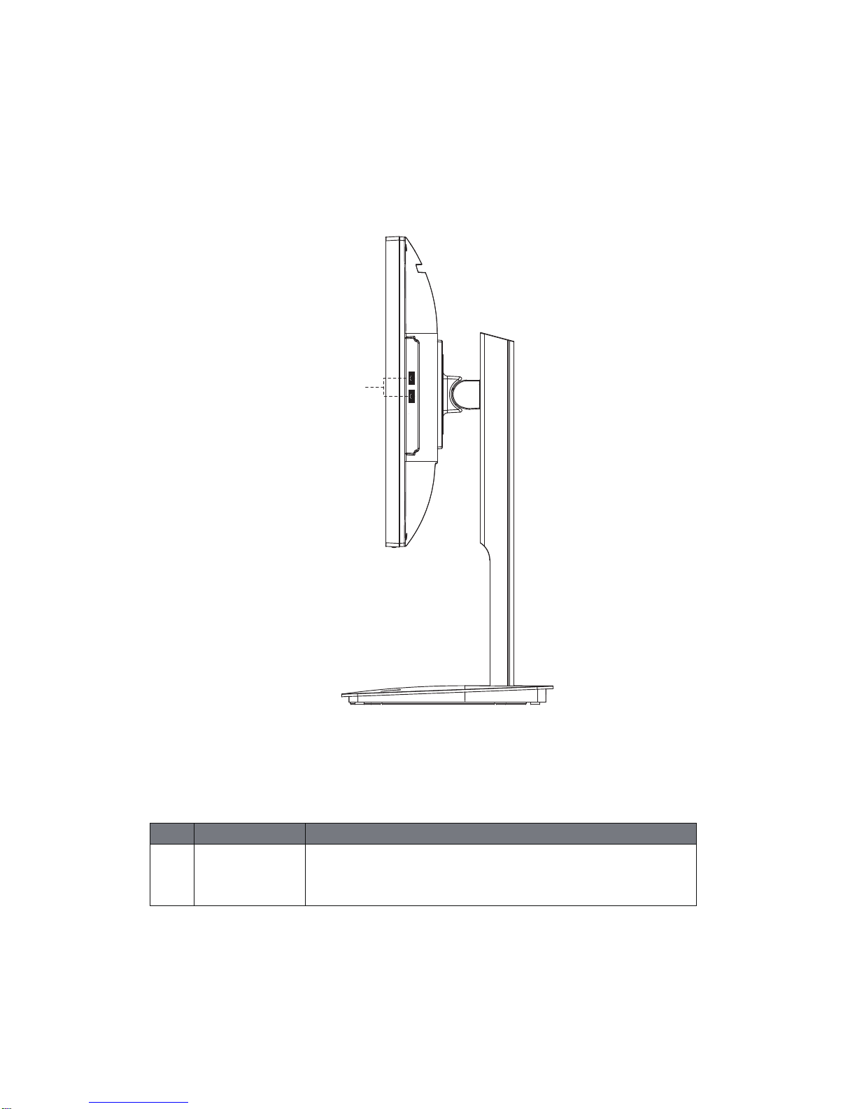
JETWAY HA238SAH-H110 User manual

JETWAY
AIO System
User's Manual
NO. HA238SAH-H110-QIG
Revision: 1.0
Release Date: July 26, 2017
1

2
Copyright
©2017 JETWAYAll rights reserved.
The trademarks mentioned in this manual are legally registered to their respective owners.
Disclaimer
Information in this manual is protected by copyright laws and is the property of JETWAY. Changes to th
e
specifications and features in this manual may be made by JETWAY without prior notice. No part of this manua
l
may be reproduced, copied, translated, transmitted, or published in any form or by any means withou
t
JETWAY's prior written permission.
Documentation Classifications
In order to assist in the use of this product, JETWAY provides the following types of documentations:
For quick set-up of the product, read the Quick Installation Guide included with the product. For detailed
product information, carefully read the User's Manual.
For product-related information, check on our website at:
http://www.jetwayipc.com/

3
Table of Contents
Overview Of Your Documentation................................................................................. 4
Box Contents................................................................................................................... 5
Specifications.................................................................................................................. 6
Getting Start With Your PC............................................................................................. 7
Adjustment of View Angle
..............................................................................................
13
Setting Up Your PC
.........................................................................................................
15
................................................................................
Appendix 1 ................................................. 17
20
11
Appendix 2
Disassembly Instructions ...............
: Precautions and Safety Notices
: Packing of Color Box
.............
...............................................................................

4
Overview Of Your Documentation
Document Type
Your documentation contains PDF user manuals to help you perform various tasks.
Document Type
User’s manual provides information about setting up your computer.
Non-printed documentation
Servicing
Typographics
Special tips, notes, and cautions that appear throughout this manual are designed to ensure that you perform
specific tasks properly, preventing unnecessary errors.
CAUTION: Indicates important information to prevent potential damage to the unit and data, or
personal injury caused by improper use.
NOTE: Indicates additional information for particular situation.
TIP
: Indicates useful information for completing a task.
Manual CD (containing this manual) provides information about using your computer, cleaning and
maintaining the monitor and the accessories, and the common solutions to problems you may
encounter while using your computer.
Do not attempt to service this product yourself, as opening or removing covers may expose you to the risk
of electric shock and other hazards. If any of the above mentioned misuse or other accidents such as
dropping or mishandling occurs, contact qualified service personnel for servicing.

5
Box Contents
Carefully unpack the system and check that the following items were included. If any are missing or
damaged, please contact your vender. Retain the box and packing in case of you need to transport
your personal computer in the future. The fitted foam packing is ideal for protecting the device during
transporting.
The appearance and contents of your package may be different from those illustrated be-low due to
regional variations.
Standard Items
AIO Power Adapter Power Cord Screwdriver
The box contents above are for reference only and the actual items shall depend on the product
package you obtain.
The box contents are subject to change without notice.
The motherboard image is for reference only.

6
Specifications
Model Jetway
Processor(CPU) Intel® Kabylake-S/Skylake-S Prozessor LGA 1151 Socket Core™i7/ i5/ i3
Support Max. 65W.
Chipset Intel® H110 Express Chipse
Operating System Windows 7 / 8.1 / 10
Memory Dual channel SODIMM DDR4 2133MHz
2 x SODIMMs. 32GB Maximum
HD drive 1 x 2.5" Hard disk(optional)
1 x MSATA (optional)
Graphics
Intel® Gen9 Graphics integrated in Intel® Processor
HDMI display 1920x1080@60Hz (max.)
DisplayPort 4096x2304@60Hz (max.)
LVDS 24-bits
Adapter 19 voltage 120 watt power adapter
Display 23.8" wide screen 16:9 HD,LED panel, Max resolution 1920 x 1080
LED Backlight
I/O port on Board
1 x DC Jack
1 x Gigabit LAN RJ45
1 x DisplayPort out
1 x HDMI out
4 x USB 3.0 port
1 x Line out
1 x MIC Jack
Chassis IO Ports
2 x USB 2.0
(Daughter Card) 1 x Card reader (4-in-1)
Media card reader 4-in-1 memory card reader(SD/MS/XD/MMC)
Network
Integrated 10/100/1000 Gigabit Ethernet
Wireless Network
WLAN 802.11bgn, via Mini-PCIE, WiFi and Bluetooth combo card
(Optional)
Audio 2 x Speaker 3 Watt for each
Environment Operation Temperature: 0∘C - 35∘C
Storage Temperature: -20∘C - 60 ∘C
Requirement Operating Relative Humidity: 10% ~ 85 % Non-condensing
Storage Relative Humidity: 10%~ 85% Non-condensing
Dimension 564mm(W) x 520mm(H) x 235mm(D)
Net Weight 8.78KG

7
Getting Start With Your PC
Touring Your PC
This section describes the views and the features of the controls, ports, buttons, components, and connectors
of your computer.
Front View
No. Item Description
1 Power Press power button to turn on computer.
2 Indicators LED indicators
2
1

8
Rear View
No Item Description
1 Vents The design of the vents is to prevent the computer from overheating. The internal
fans blow hot air away from heat-sensitive components in the computer.
Keep the vents clean and free of dirt and dust, as blocking it may cause serious thermal problems.
2 Computer Stand You can adjust the computer stand for the best viewing angle.
1
2

9
Right-side View
No Item Description
1 USB 2.0 Ports Connect the USB plugs into the USB ports to connect your USB devices, such as
MP3 players, digital cameras, keyboard and mouse, or external hard disk drives,
etc.
1

10
Bottom-side View
No Item Description
1 DC Power Connector Connect the DC power to this port
2 USB3.0
3 DisplayPort
4 HDMI
5 RJ45 LAN Port
6 Line Out Jack
7 Mic In Jack The default MIC In jack. Microphone can be connected to MIC in jack.
Ver 2.0
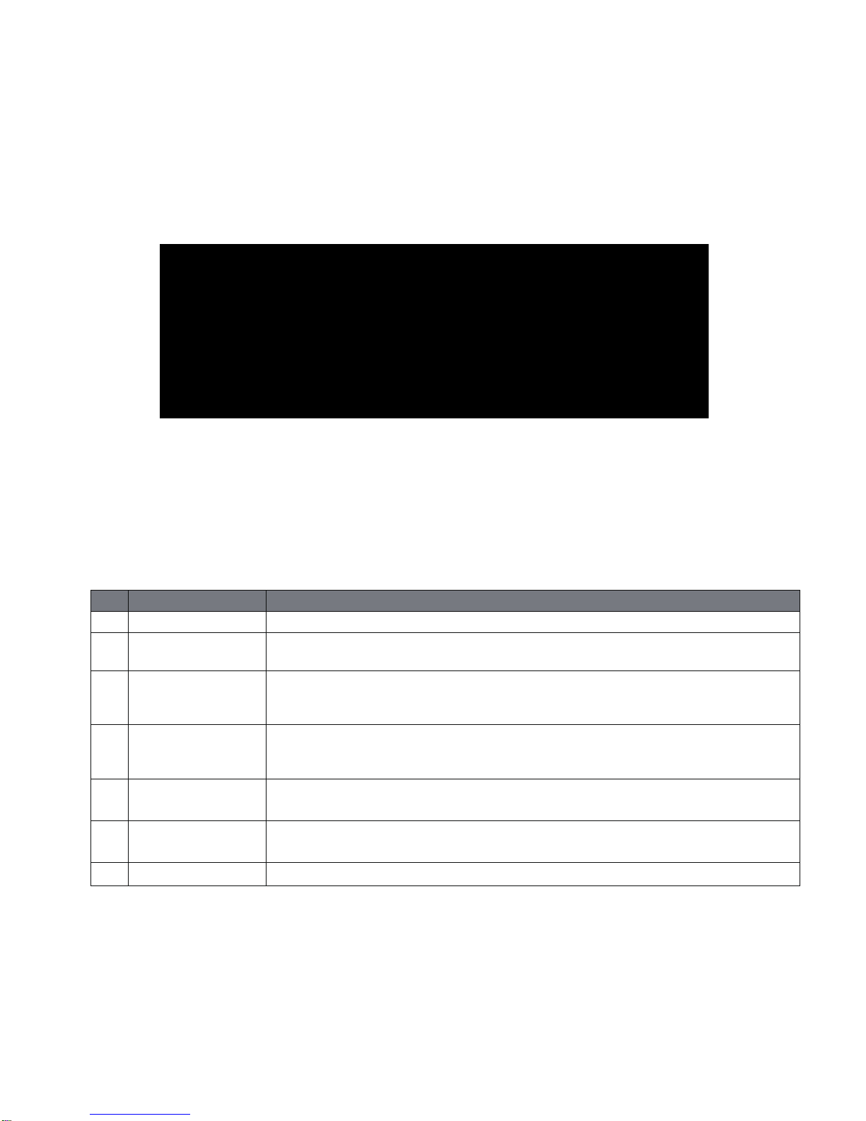
DisplayPort DisplayPort is a digital display interface which is primarily used to connect a video source to a
display device such as a computer monitor, though it can also be used to transmit audio, USB, and other forms
of data.
USB3.0 The USB port supports the USB3.0 specification. Use this port for USB devices such as a USB
keyboard/mouse, USB printer, USB flash drive and etc.
HDMI The HDMI provides an all-digital audio/video interface to transmit the uncompressed audio/video signals
and is HDCP compliant. Connect the HDMI audio/video device to this port. The HDMI technology can support
a maximum resolution of 1920x1080 but the actual resolutions support depend on the monitor being used.
RJ45 LAN Port The Gigabit Ethernet LAN port provides internet connection at up to 1 Gbps data rate.The
following describes the states of the LAN port LEDs.
Line Out Jack The default Line Out jack. Stereo speakers, earphone or front surround speakers can be
connected to Line Out jack.

11
Disassembly Instructions
Follow steps below to disassemble the AIO.
Face Down the AIO
Face down the AIO on a smooth surface using a soft material between surface and AIO to protect faceplate.
Remove the Back Cover
Remove the back cover by removing the 9 fixed screws.(Red circle)Then pull over back cover.
Separate MB Shield Cover
Remove the 8 fixed screws and lift the shield cover.

12
Separate the CPU Thermal Module
Loosen the 6 fixed screws and lift the CPU thermal module.
Separate the DRAM Thermal Module
HDD bracket separate
Loosen 4 screws to separate HDD-bracket

13
Adjustment of View Angle
Tilt Range (degree):
Backward 20°~23° Tilt Range (degree):
Forward -5°~-2°
Lift Range:
130mm+/-5mm

14
Pivot function: The screen of the All-In-One PC is 90 degree rotatable.
In order to avoid scratching foot stand and bezel, move screen up, then rotate.
To adjust the image alignment, follow steps A and B.
A. Right-click on the desktop then select “Display settings”.
B. Move cursor to Orientation pull down menu, then click your desired orientation option.

15
Setting Up Your PC
This section describes how to set up your computer and make adjustments to the monitor.
Preparing To Setup Your PC
Before attempting to set up your computer, to protect the computer and monitor, you should:
•find a flat open area on your desk to position your computer.
•place a soft item like the computer packaging bag on the desk for padding.
It is suggested to install your computer in a space that allows for airflow as restricting the airflow
may cause overheating which could impact the performance of your computer.
1. Gently lay the screen face down on a flat clean padded surface.
2. Pick out the stand base body and the lifting stand (Part No.1 & No.2 ).
3. Lock the base to the lifting stand by tightening the screws.
4. Align the screw holes on the back cover of the computer reserved for VSEA Mount with
corresponding ones on the stand and lock with the screws.
5. Carefully lift the computer and adjust the angle of the screen.
Part2
Part1

16
Turning On Your PC
After you finish the installation of your computer, press the Power computer to turn it on. Then follow
the on-screen instructions to complete the initial setup.
Turning Off Your PC
To turn off the system, close all the active windows, and then click the Windows start menu at bottom
left corner of your screen, then click power button then click Shutdown button.

17
Appendix 1
Safety Precautions
Observe all cautions and safety related notes located inside the display cabinet and on the display chassis.
Operation of these displays outside the cabinet or with the cover removed involves a shock hazard from the
display backlight’s inverter. Work on the display should not be attempted by anyone who is not thoroughl
y
familiar with precautions necessary when working on high voltage equipment.
Before returning a serviced display to the customer, a thorough safety test must be performed to verify that
the display is safe to operate without danger or shock.
Product Safety Notice
Many electrical and mechanical parts in this chassis provide special visual safety protection. The protectio
n
afforded by them cannot necessarily be obtained by using replacement components rated for higher voltag
e,
wattage, etc.
Before replacing any of these components, read the parts list included in this manual carefully. The use o
f
substitute replacement parts, which do not have the same safety characteristics, as specified in the parts lis
t
may create shock, fire or other hazards, and hence should be prohibited.
Service Notes
When replacing parts or circuit boards, wrap the wires around terminals before soldering.
Keep wires away from high temperature components.
Keep cable and their shielding in their original position so as to reduce interference.
: Precautions and Safety Notices

18
Take out foam on left and right side. Take out theAIO by grasping top of the machine.
Handing and Placing Methods
Correct Methods Incorrect Methods
Only touch the metal frame of the LCD panel .
Do not touch surface of the polarizer.
Pressing surface of LCD panel with fingers, may scratch
the surface of panel.

19
19
Place the AIO on clean and soft foam pad. Placing AIO on foreign objects, could scratch the
surface of the panel.
If panel is placed face down on the lap, that could
scratch the surface of the panel.

20
Put the AIO in the EPE bag
AIO Body
Stand
Right EPE
cushion
Left EPE
cushion
Stand EPE
cushion
Place the AIO into the carton and then put all accessories into the box and then seal the carton
with tape.
Stand Base
Power cord and a screw Adapter
Appendix 2: Packing of Color Box
Table of contents
Other JETWAY Desktop manuals

JETWAY
JETWAY 2USER-QIG-MINIQ-R1.1 User manual

JETWAY
JETWAY Mini-TOP Series User manual

JETWAY
JETWAY JBC501F697-Q170-B User manual

JETWAY
JETWAY HBFMF833W Series User manual

JETWAY
JETWAY FCT95 Operating and maintenance instructions

JETWAY
JETWAY G03-JC330MU10QIG-F User manual

JETWAY
JETWAY HM-1000 Series User manual