JETWAY 845GEA1A User manual

845GPro/845GProL
845GEA/845GEAL
845PEA/845PEAL
USER'S MANUAL
M/B For Socket 478 Pentium 4 Processor
NO. G03-845GEA1A
Release date: October 2002
Trademark:
* Specifications and Information contained in this documentation are furnished for information use only, and are
subject to change at any time without notice, and should not be construed as a commitment by manufacturer.

i
USER’S NOTICE...........................................................................................................................ii
MANUAL REVISION INFORMATION..........................................................................................ii
COOLING SOLUTIONS ..............................................................................................................ii
CHAPTER 1 INTRODUCTION OF 845GPro/845GProL/845GEA/845GEAL/845PEA/845PEAL
MOTHERBOARD
1-1 FEATURE OF MOTHERBOARD...................................................................................... 1
1-2 SPECIFICATION ...........................................................................................................2
1-3 PERFORMANCE LIST .................................................................................................... 3
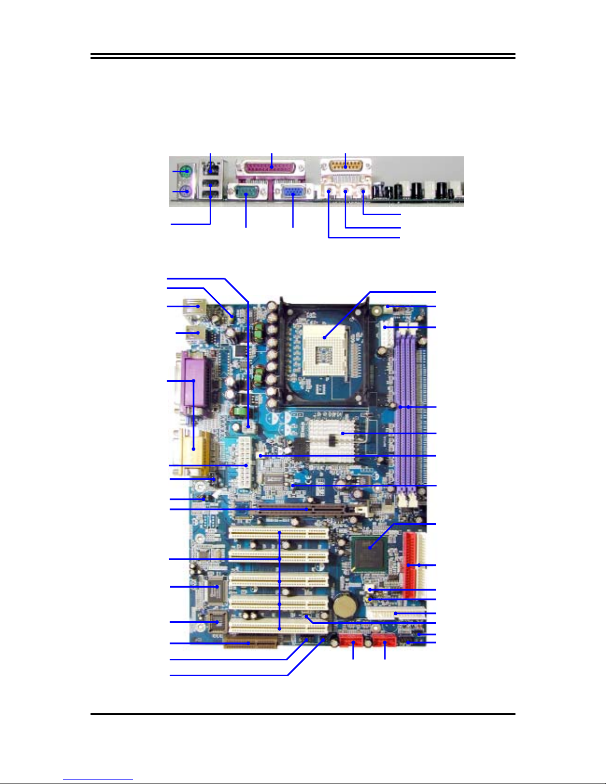
1-4 LAYOUT DIAGRAM & JUMPER SETTING .....................................................................4
CHAPTER 2 HARDWARE INSTALLATION
2-1 HARDWARE INSTALLATION STEPS...............................................................................6
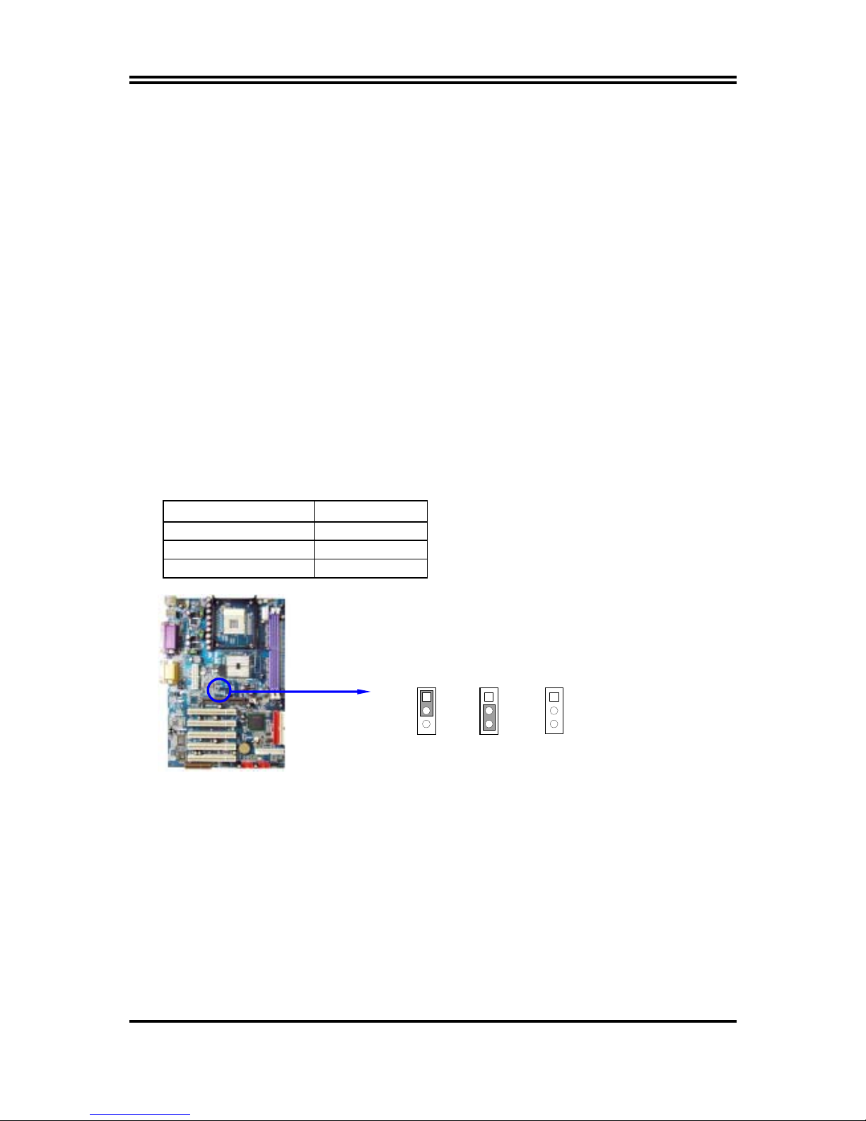
2-2 CHECKING MOTHERBOARD'S JUMPER SETTING .......................................................6
2-3 INSTALL CPU ................................................................................................................7
2-3-1 GLOSSARY....................................................................................................... 7
2-3-2 ABOUT INTEL PENTIUM 4 478-PIN CPU........................................................... 8
2-4 INSTALL MEMORY ....................................................................................................... 9
2-5 EXPANSION CARD...................................................................................................... 9
2-5-1 PROCEDURE FOR EXPANSION CARD INSTALLATION ...................................10
2-5-2 ASSIGNING IRQ FOR EXPANSION CARD ...................................................... 10
2-5-3 INTERRUPT REQUEST TABLE FOR THIS MOTHERBOARD .................................. 10
2-5-4 AGP SLOT ........................................................................................................ 11
2-6 CONNECTORS, HEADERS ...........................................................................................12
2-6-1 CONNECTORS.................................................................................................13
2-6-2 HEADERS.......................................................................................................... 15
2-7 STARTING UP YOUR COMPUTER................................................................................. 18
CHAPTER 3 INTRODUCING BIOS
3-1 ENTERING SETUP.......................................................................................................... 19
3-2 GETTING HELP .............................................................................................................19
3-3 THE MAIN MENU.......................................................................................................... 20
3-4 STANDARD CMOS FEATURES......................................................................................21
3-5 ADVANCED BIOS FEATURES .......................................................................................22
3-6 ADVANCED CHIPSET FEATURES .................................................................................24
3-6-1 DRAM TIMING SETTINGS ................................................................................25
3-7 INTEGRATED PERIPHERALS..........................................................................................26
3-7-1 ONBOARD IDE FUNCTION .............................................................................26
3-7-2 ONBOARD DEVICE FUNCTION ......................................................................27
3-7-3 ONBOARD SUPER IO FUNCTION....................................................................28
3-8 POWER MANAGEMENT SETUP....................................................................................29
3-8-1 PM TIMER RELOAD EVENTS............................................................................30
3-9 PNP/PCI CONFIGURATION SETUP..............................................................................31
3-9-1 IRQ RESOURCES .............................................................................................32
3-10 PC HEALTH STATUS..................................................................................................... 32
3-11 MISCELLANEOUS CONTROL...................................................................................... 33
3-12 LOAD STANDARD/OPTIMIZED DEFAULTS.................................................................. 34
3-13 SET SUPERVISOR/USER PASSWORD........................................................................... 34
CHAPTER 4 DRIVER & FREE PROGRAM INSTALLATION
MAGIC INSTALL SUPPORTS WINDOWS 95/98/98SE/NT4.0/2000....................................... 35
4-1 INF INSTALL INTEL 845 CHIPSET SYSTEM DRIVER ................................ 36
4-2 IAA INSTALL INTEL APPLICATION ACCELERATOR SOFTWARE ...........36
4-3 VGA INSTALL INTEL 845G VGA DRIVER ................................................37
4-4 SOUND INSTALL CMI9738 AUDIO CODEC DRIVER ..................................37
4-5 LAN INSTALL RTL8100 LAN CONTROLLER DRIVER................................ 39
4-6 PC-HEALTH INTEL 845 PC-HEALTH MONITOR ......................................................... 40
4-6-1 HOW TO UTILIZE PC-HEALTH.......................................................................... 41
4-7 MAGIC BIOS INSTALL BIOS LIVE UPDATE UTILITY ............................................... 41
4-8 PC-CILLIN INSTALL PC-CILLIN2002 ANTI-VIRUS PROGRAM.........................43
4-9 HOW TO INSTALL USB 2.0 DRIVER ..............................................................................44
4-10 HOW TO DISABLE ON-BOARD SOUND ......................................................................45
4-11 HOW TO UPDATE BIOS................................................................................................45
TABLE OF CONTENT

ii
USER’S NOTICE
COPYRIGHT OF THIS MANUAL BELONGS TO THE MANUFACTURER. NO PART OF THIS
MANUAL, INCLUDING THE PRODUCTS AND SOFTWARE DESCRIBED IN IT MAY BE
REPRODUCED, TRANSMITTED OR TRANSLATED INTO ANY LANGUAGE IN ANY FORM OR
BY ANY MEANS WITHOUT WRITTEN PERMISSION OF THE MANUFACTURER.
THIS MANUAL CONTAINS ALL INFORMATION REQUIRED TO USE 845GPro/845GProL
/845GEA/845GEAL/845PEA/845PEAL MOTHER-BOARD AND WE DO ASSURE THIS MANUAL
MEETS USER’S REQUIREMENT BUT WILL CHANGE, CORRECT ANY TIME WITHOUT NOTICE.
MANUFACTURER PROVIDES THIS MANUAL “AS IS” WITHOUT WARRANTY OF ANY KIND,
AND WILL NOT BE LIABLE FOR ANY INDIRECT, SPECIAL, INCIDENTIAL OR CONSEQUENTIAL
DAMAGES (INCLUDING DAMANGES FOR LOSS OF PROFIT, LOSS OF BUSINESS, LOSS OF USE
OF DATA, INTERRUPTION OF BUSINESS AND THE LIKE).
PRODUCTS AND CORPORATE NAMES APPEARING IN THIS MANUAL MAY OR MAY NOT BE
REGISTERED TRADEMARKS OR COPYRIGHTS OF THEIR RESPECTIVE COMPANIES, AND
THEY ARE USED ONLY FOR IDENTIFICATION OR EXPLANATION AND TO THE OWNER’S
BENEFIT, WITHOUT INTENT TO INFRINGE.
Manual Revision Information
Reversion Revision History Date
1.0 First Release October 2002
Item Checklist
5845GPro/845GProL/845GEA/845GEAL/845PEA/845PEAL Motherboard
5Cable for IDE/Floppy
5CD for motherboard utilities
□Cable for USB Port 3/4 (Option)
5845GPro/845GProL/845GEA/845GEAL/845PEA/845PEAL User’s Manual
Intel Pentium 4 Processor Family
Cooling Solutions
As processor technology pushes to faster speeds and higher performance, thermal management
becomes increasingly crucial when building computer systems. Maintaining the proper thermal
environment is key to reliable, long-term system operation. The overall goal in providing the proper
thermal environment is keeping the processor below its specified maximum case temperature.
Heatsinks induce improved processor heat dissipation through increased surface area and
concentrated airflow from attached fans. In addition, interface materials allow effective transfers of
heat from the processor to the heatsink. For optimum heat transfer, Intel recommends the use of
thermal grease and mounting clips to attach the heatsink to the processor.
When selecting a thermal solution for your system, please refer to the website below for collection of
heatsinks evaluated and recommended by Intel for use with Intel processors. Note, those heatsinks are
recommended for maintaining the specified Maximum T case requirement. In addition, this collection
is not intended to be a comprehensive listing of all heatsinks that support Intel processors.
For vendor list of heatsink and fan, please visit :
http://developer.intel.com/design/Pentium4/components/index

1
Chapter 1
Introduction of 845GPro/845GProL/845GEA/845GEAL/
845PEA/845PEAL Motherboard
1-1 Feature of motherboard
The 845GPro/845GProL/845GEA/845GEAL/845PEA/845PEAL motherboard is design for
use Intel Pentium 4 Processor in 478 Pin Package/Northwood Processor with the Intel 845G
Chipset delivers a high performance and professional desktop platform solution. Which utilize
the Socket 478 design and the memory size expandable to 2.0GB.
These motherboards use the newest Intel 845G/845GE/845PE Chipset Supports 533MHz
System Bus in data transfer rate. And the 845GPro/845GProL provided 133MHz SDRAM
clock frequency support DDR266 SDRAM, the 845GEA/845GEAL/845PEA/845PEAL
provided 166MHz SDRAM clock frequency support DDR333 SDRAM. The motherboard
offers ULTRA ATA 100 to provide speedier HDD throughout that boosts overall system
performance.
845GPro/845GProL/845GEA/845GEAL with integrated 2D/3D Graphics Accelerator which
supports 256 bit graphics core, and supports hardware motion compensation assist for software
MPEG/DVD decode, makes this board lower cost alternative to a video card. For those wanting
even greater graphic performance, an AGP 4X slot is included on the board (For 1.5V AGP
card only. No for 3.3V or Universal AGP card). This AGP slot will support either a 4X
VGA card or Intel Digital Video Out ports add support for digital displays and TV-out .
The 845GProL/845GEAL/845PEAL motherboard including PCI LAN Controller chip support
10/100 Mb/sec Base transfer rate.
These motherboards also has an integrated AC’97 2.1 CODEC on board support 4-channel 3D
surround positioning Audio, which is fully compatible with Sound Blaster Prothat gives
you the best sound quality and compatibility.
With USB control as well as capability of expanding to 6 USB2.0 function ports, these
motherboards meet future USB demand also this motherboard has built-in hardware monitor
function. This will monitor and protect your computer. These motherboards special design in
hardware to protect BIOS from virus crash BIOS data.
These motherboards provide special function in BIOS Setup to setting CPU Host clock step
by step increasing let users to approach over clocking.
These motherboards provided high performance & meet future specification demand. It is
really wise choice for your computer.

2
1-2 Specification
Spec Description
Design ∗ATX form factor 4 layers PCB size: 30.5x21.0cm
Chipset ∗Intel 845G Graphics Memory Controller Hub (GMCH) Chipset
for 845GPro/845GProL
∗Intel 845GE (GMCH) Chipset for 845GEA/845GEAL
∗Intel 845PE (MCH) Chipset for 845PEA/845PEAL
∗Intel 82801DB I/O Controller Hub (ICH4) Chipset
CPU Socket
(mPGA478B Socket)
∗Support Intel Pentium 4 478 Pin package utilizes Flip-Chip Pin
Grid Array (FC-PGA2) package processor
∗Support CPU Frequency 400MHz & 533MHz
∗Support 1.5G∼2.8G 478 Pin Pentium 4 processor
∗Reserves support for future Intel Pentium 4 processors
Memory Socket ∗184-pin DDR SDRAM module socket x2
∗Support DDR266/DDR200 DRAM for 845GPro/845GProL
∗Support DDR333 for 845GEA/845GEAL/845PEA/845PEAL
∗Expandable to 2.0GB
Expansion Slot &
Headers
∗AGP slot x1 for AGP 1.5V standard only, support AGP 2.0 &
4X mode
∗32-bit PCI slot x5, CNR slot x1
Integrate IDE ∗Two PCI IDE controllers support PCI Bus Mastering, ATA
PIO/DMA and the ULTRA DMA 33/66/100 functions that
deliver the data transfer rate up to 100 MB/s
LAN On Board
(Only for 845GProL/
845GEAL/845PEAL)
∗Realtek RTL8100BL PCI LAN Controller chip
∗Supports 10/100 Mb/sec data transfer rate
Audio ∗AC’97 Digital Audio controller integrated
∗AC’97 2.1 Audio CODEC on board support 4-channel Audio
∗Audio driver and utility included
BIOS ∗Award 2MB Flash ROM
Multi I/O ∗PS/2 keyboard and PS/2 mouse connectors
∗Floppy disk drive connector x1
∗Parallel port x1, Serial port x2
∗USB 2.0 connector x2
∗USB 2.0 headers x2 (connecting cable option)
∗Audio connector Line-in, Line-out, MIC & Game Port

3
1-3 Performance List
The following performance data list is the testing result of some popular benchmark testing
programs. These data are just referred by users, and there is no responsibility for different
testing data values gotten by users (the different Hardware & Software configuration will
result in different benchmark testing results.)
Performance Test Report
CPU: Intel Pentium 4 1.9GHz mPGAB package
DRAM: 256MB DDR266 SDRAM x1 (SAMSUNG K4H280838B-TCB0)
VGA Expansion Card: NVDIA Geforce2 MX400-64MB (1024x768 Hi-color)
Hard Disk Driver: IBM DTLA-305040 (ATA-100)
BIOS: Award Optimal default
OS: Win 98SE
Frame Buffer
8M On Board
VGA
Geforce2
MX200
Geforce2
MX400
3D Mark 2000 3392 2917 5408
3D Mark 2001SE 1420 1217 2555
3D Winbench 2000 69.8 55.5 104
Final Reality 12.07 10.18 10.06
Content Creation Winstone 2000 44.6 43.8 44.5
Content Creation Winstone 2001 52.5 55.8 56.1
Content Creation Winstone 2002 19.9 20.8 20.8
Business Winstone 2001 46 46.1 46.7
Winbench 99:
CPU Mark 99 113 110 113
FPU Winmark 99 6640 6620 6620
Business Disk Winmark99 5110 5230 5230
Hi-end Disk Winmark99 17100 18800 16600
Business Graphic Winmark 375 408 438
Hi-end Graphic Winmark 1110 1260 1270
SYS Mark 2000/2001 : SISMark 2000/2001 Rating (Internet Content Creation / Office
Productivity)
SISMark 2000 211 (232/196) 215 (233/203) 216 (232/205)
SISMark 2001 156 (172/142) 151 (172/133) 154 (171/138)
SISOFT Sandra 2002 :
Dhrystone ALU MIPS 3577 3578 3582
Whetstone FPU MFLOPS 1141/2378 1149/2359 1142/2356
RAM Int Buffered iSSE2 MB/S 1900 2033 2033
RAM Float Buffered iSSE2 MB/S 1831 1947 1944
Integer SSE2 IT/S 7582 7570 7565
Floating-Point SSE2 IT/S 9200 9206 9219
QUAKE3 DEMO1 FPS 76.6 118.9 172.1
DEMO2 FPS 76.3 120.2 173.0
WCPUID System / CPU Clock 101/1918.93 101/1918.92 101/1918.93

4
1-4 Layout Diagram & Jumper Setting
Winbond 83627HF Chip
IR Connector
CNR Slot
Front Panel Audio
PC99 Back Panel
CD Audio
PCI Slot
AGP Slot
K/B Power ON
Jumper (JP1)
Floppy Connector
Intel Chipset
Front Panel Connector
ATA 100 IDE Conn.
Clear CMOS (JP5)
ATX Power Conn.
USB Port
(USB3, USB2)
CPU FAN
2MBit Flash ROM BIOS
CPU Socket
DDR DIMM X2
Wake On LAN
SYSFAN1
Intel 82801DB Chip
ATX 12V Power Conn.
USB Port
/LAN Connector
(for 845GproL/
845GEAL/845PEAL)
PS2 KB/Mouse Port
LINE-OUT
LINE-IN
MIC
GAME/MIDI PORT
COM1 VGA
(for 845GPro/845GProL/
845GEA/845GEAL)
PS/2 MOUSE
PS/2 Keyboard
USB
PRINT
(for 845GProL/
845GEAL/845PEAL)
LAN
ATX P9 Power Conn.
Speak Connector
SYSFAN2
COM2 Connector
CPU Frequency Select
(JP2)

5
Jumpers
Jumper Name Description Page
JP2 CPU Frequency Select 3-pin Block P.6
JP5 CMOS RAM Clear 3-pin Block P.6
JP1 Keyboard Power On Enable/Disabled 3-pin Block P.7
Connectors
Connector Name Description Page
ATXPWR ATX Power Connector 20-pin Block P.12
ATX12V ATX 12V Power Connector 4-pin Block P.12
ATXP6 ATX P9 Power Connector 6-pin Block P.12
KB
(PS2 KB/MOUSE)
PS/2 Mouse & PS/2 Keyboard
Connector
6-pin Female P.13
UL_B1(USB1) USB Port Connector 4-pin Connector P.13
LAN LAN Connectors RJ-45 Connector P.13
PARALLEL Parallel Port Connector 25-pin Female P.13
GAME Audio/Game Connector 3 phone jack + 15-pin Connector P.13
VGA
(845GPro/845GproL/
845GEA/845GEAL)
VGA Display Connector 15-pin Female Connector P.13
COM1 Serial Port COM1
Connector
9-pin Connector P.13
FDD Floppy Driver Connector 34-pin Block P.14
IDE1/IDE2 Primary/Secondary IDE
Connector
40-pin Block P.14
Only for 845GProL/845GEAL/845PEAL
Headers
Header Name Description Page
COM2 Serial Port COM2 Header 9-pin Block P.15
AUDIO Line-In/Out, MIC header 9-pin Block P.15
USB2/USB3 USB Port Headers 9-pin Block P.15
SPEAK Speaker connector 4-pin Block P.16
FP
(Power LED/Reset/
IDE LED/ Power Button)
Front Panel Header
(including Power LED/ IDE activity LED/
Reset switch / Power On Button lead)
9-pin Block P.16
WOL Wake On-LAN Headers 3-pin Block P.16
SYSFAN1, SYSFAN2,
CPUFAN
FAN Speed Headers 3-pin Block P.17
IR IR infrared module Headers 5-pin Block P.17
CDIN CD Audio-In Headers 4-pin Block P.17
Expansion Sockets
Socket/Slot Name Description Page
ZIF Socket 478 CPU Socket 478-pin mPGAB CPU Socket P.8
DDR1, DDR2 DDR Module Socket 184-pin DDR SDRAM Module
Expansion Socket
P.9
PCI1 ∼PCI5 PCI Slot 32-bit PCI Local Bus Expansion slots P.9
AGP AGP 4X Mode Slot AGP Expansion Slot P.11
CNR CNR Slot Communication Network Riser Slot

6
Chapter 2
Hardware installation
2-1 Hardware installation Steps
Before using your computer, you had better complete the following steps:
1. Check motherboard jumper setting
2. Install CPU and Fan
3. Install System Memory (DIMM)
4. Install Expansion cards
5. Connect IDE and Floppy cables, Front Panel /Back Panel cable
6. Connect ATX Power cable
7. Power-On and Load Standard Default
8. Reboot
9. Install Operating System
10. Install Driver and Utility
2-2 Checking Motherboard’s Jumper Setting
(1) CPU Frequency Select (3-pin) : JP2
CPU Clock JP2
AUTO 1-2 closed
100 (400) MHz 2-3 closed
133 (533) MHz Open
CPU Frequency Select
100MHz
JP2
1
3
JP2
1
3
AUTO 133MHz
JP2
1
3
(2) CMOS RAM Clear (3-pin) : JP5
A battery must be used to retain the motherboard configuration in CMOS RAM short 1-2
pins of JP5 to store the CMOS data.
To clear the CMOS, follow the procedure below:
1. Turn off the system and unplug the AC power
2. Remove ATX power cable from ATX power connector
3. Locate JP5 and short pins 2-3 for a few seconds
4. Return JP5 to its normal setting by shorting pins 1-2
5. Connect ATX power cable back to ATX power connector

7
Note: When should clear CMOS
1. Troubleshooting
2. Forget password
3. After over clocking system boot fail
CMOS RAM Clear Setting
JP5
13
2-3 closed Clear CMOS
JP5
1 3
1-2 closed Normal (Default)
(3) Keyboard Power On function Enabled/Disabled: JP1
When setting Enabled you can using keyboard by key in password to power on system.
Keyboard Power On Setting
2-3 closed K/B Power ON Enabled
JP1 1
3
JP1 1
3
1-2 closed K/B Power ON Disable
(Default)
2-3 Install CPU
2-3-1 Glossary
Chipset (or core logic) - two or more integrated circuits which control the interfaces between
the system processor, RAM, I/O devises, and adapter cards.
Processor slot/socket - the slot or socket used to mount the system processor on the
motherboard.
Slot (AGP, PCI, ISA, RAM) - the slots used to mount adapter cards and system RAM.
AGP - Accelerated Graphics Port - a high speed interface for video cards; runs at 1X
(66MHz), 2X (133MHz), or 4X (266MHz).
PCI - Peripheral Component Interconnect - a high speed interface for video cards, sound
cards, network interface cards, and modems; runs at 33MHz.
ISA - Industry Standard Architecture - a relatively low speed interface primarily used for
sound cards and modems; runs at approx. 8MHz.
Serial Port - a low speed interface typically used for mouse and external modems.
Parallel Port - a low speed interface typically used for printers.
PS/2 - a low speed interface used for mouse and keyboards.

8
USB - Universal Serial Bus - a medium speed interface typically used for mouse, keyboards,
scanners, and some digital cameras.
Sound (interface) - the interface between the sound card or integrated sound connectors and
speakers, MIC, game controllers, and MIDI sound devices.
LAN (interface) - Local Area Network - the interface to your local area network.
BIOS (Basic Input/Output System) - the program logic used to boot up a computer and
establish the relationship between the various components.
Driver - software, which defines the characteristics of a device for use by another device or
other software.
Processor - the "central processing unit" (CPU); the principal integrated circuit used for doing
the "computing" in "personal computer"
Front Side Bus Frequency - the working frequency of the motherboard, which is generated
by the clock generator for CPU, DRAM and PCI BUS.
CPU L2 Cache - the flash memory inside the CPU, normally Athlon CPU has 256K or above,
while Duron will have 64K.
2-3-2 About Intel Pentium 4 478-pin CPU
This motherboard provides a 478-pin surface mount, Zero Insertion Force (ZIF) socket,
referred to as the mPGA478B socket supports Intel Pentium 4 processor in the 478 Pin
package utilizes Flip-Chip Pin Grid Array (FC-PGA2) package technology.
The CPU that comes with the motherboard should have a cooling FAN attached to prevent
overheating. If this is not the case, then purchase a correct cooling FAN before you turn on
your system.
WARNING! Be sure that there is sufficient air circulation across the processor’s
heatsink and CPU cooling FAN is working correctly, otherwise it may
cause the processor and motherboard overheat and damage, you may install
an auxiliary cooling FAN, if necessary.
To install a CPU, first turn off your system and remove its cover. Locate the ZIF socket and
open it by first pulling the level sideways away from the socket then upward to a 90-degree
angle. Insert the CPU with the correct orientation as shown below. The notched corner
should point toward the end of the level. Because the CPU has a corner pin for two of the
four corners, the CPU will only fit in the orientation as shown.
CPU ZIF mPGAB Socket
Colden Arrow
mPGA478B
When you put the CPU into the ZIF socket. No force require to insert of the CPU, then press
the level to Locate position slightly without any extra force.

9
2-4 Install Memory
This motherboard provides two 184-pin DUAL INLINE MEMORY MODULES (DIMM)
sites for memory expansion available from minimum memory size of 64MB to maximum
memory size of 2.0GB DDR SDRAM.
Valid Memory Configurations
Bank 184-Pin DIMM Total Memory
Bank 0, 1 (DDR1) DDR200/DDR266/DDR333
DDR SDRAM Module
X1 64MB∼1.0GB
Bank 2, 3 (DDR2) DDR200/DDR266 /DDR333
DDR SDRAM Module
X1 64MB∼1.0GB
Total System Memory (Max. 2.0GB) 2 64MB∼2.0GB
NOTE! Make sure the installed memory are DDR266 SDRAM support 133MHz
memory clock, otherwise the system may hang during startup.
Generally, installing DDR SDRAM modules to your motherboard is very easy, you can refer
to figure 2-4 to see what a 184-Pin DDR266/DDR200 DDR SDRAM module looks like.
DDR2 (BANK2+ BANK3)
DDR1 (BANK0+ BANK1)
NOTE! When you install DIMM module fully into the DIMM socket the eject tab should
be locked into the DIMM module very firmly and fit into its indention on both
sides.
WARNING! For the DDR SDRAM CLOCK is set at 133MHz, use only DDR266-compliant DDR
Modules. When this motherboard operate at 133Mhz, most system will not even
boot if non-compliant modules are used because of the strict timing issues, if your
SDR Modules are not DDR266-compliant, set the DDR SDRAM clock to 100MHz
to ensure system stability.
2-5 Expansion Cards
WARNING! Turn off your power when adding or removing expansion cards or other system
components. Failure to do so may cause severe damage to both your motherboard
and expansion cards.
2-5-1 Procedure For Expansion Card Installation
Figure 2-4

10
1. Read the documentation for your expansion card and make any necessary hardware or
software setting for your expansion card such as jumpers.
2. Remove your computer’s cover and the bracket plate on the slot you intend to use.
3. Align the card’s connectors and press firmly.
4. Secure the card on the slot with the screen you remove above.
5. Replace the computer system’s cover.
6. Set up the BIOS if necessary.
7. Install the necessary software driver for your expansion card.
2-5-2 Assigning IRQs For Expansion Card
Some expansion cards need an IRQ to operate. Generally, an IRQ must exclusively assign to
one use. In a standard design, there are 16 IRQs available but most of them are already in use.
Standard Interrupt Assignments
IRQ Priority Standard function
0 N/A System Timer
1 N/A Keyboard Controller
2 N/A Programmable Interrupt
3 * 8 Communications Port (COM2)
4 * 9 Communications Port (COM1)
5 * 6 Sound Card (sometimes LPT2)
6 * 11 Floppy Disk Controller
7 * 7 Printer Port (LPT1)
8 N/A System CMOS/Real Time Clock
9 * 10 ACPI Mode when enabled
10 * 3 IRQ Holder for PCI Steering
11 * 2 IRQ Holder for PCI Steering
12 * 4 PS/2 Compatible Mouse Port
13 N/A Numeric Data Processor
14 * 5 Primary IDE Channel
15 * 1 Secondary IDE Channel
* These IRQs are usually available for ISA or PCI devices.
2-5-3 Interrupt Request Table For This Motherboard
Interrupt request are shared as shown the table below:
INT A INT B INT C INT D INT E INT F INT G INT H
Slot 1 √
Slot 2 √
Slot 3 √
Slot 4 √
Slot 5 √
Onboard VGA √
Onboard LAN √
Onboard USB 1 √
Onboard USB 2 √
Onboard USB 3 √
AC97/MC97 √

11
IMPORTANT! If using PCI cards on shared slots, make sure that the drivers support
“Shared IRQ” or that the cards don’t need IRQ assignments. Conflicts will
arise between the two PCI groups that will make the system unstable or
cards inoperable.
2-5-4 AGP Slot
This motherboard provides an AGP Slot, only support the 1.5V 4X AGP VGA card.
Do not use AGP 2X card (3.3V) in this motherboard. It will burn and damage the
motherboard due to Intel® 845 chipset can not support AGP 2X (3.3V).
The AGP Slot also supports AGP Digital Display Card for digital display and TV-out.
IMPORTANT! Before you plug-in AGP card, please make sure the following notice is
fully understood and practiced. If your AGP card has “AGP 4X notch
(show below) please make sure your AGP card is AGP 4X (1.5V) not
AGP 2X (3.3V)
AGP SLOT
Example 1: SiS 305 & ATi Rage 128 Pro AGP card those golden finger is compatible
with 2X/4X mode AGP slot, but only can support 2X (3.3V) only. If you
install these cards in Intel® 845 based motherboard it will burn and damage
the motherboard.
Example 2: We also find Diamond Vipper V770 golden finger is design for 2X/4X mode
AGP Slot. It can be adjusted the jumper for AGP 2X (3.3V) or AGP 4X
(1.5V). But the factory default setting is 2X (3.3V). If you install this AGP
card in motherboard without change the jumper setting to 4X (1.5V), it will
burn the motherboard.
2x notch 4x notch

12
2-6 Connectors, Headers
2-6-1 Connectors
(1) Power Connector (20-pin block) : ATXPWR
ATX Power Supply connector. This is a new defined 20-pins connector that usually
comes with ATX case. The ATX Power Supply allows to use soft power on momentary
switch that connect from the front panel switch to 2-pins Power On jumper pole on the
motherboard. When the power switch on the back of the ATX power supply turned on,
the full power will not come into the system board until the front panel switch is
momentarily pressed. Press this switch again will turn off the power to the system
board.
PIN ROW2 ROW1
1 3.3V 3.3V
2 -12V 3.3V
3 GND GND
4 Soft Power On 5V
5 GND GND
6 GND 5V
7 GND GND
8 -5V Power OK
9 +5V +5V (for Soft Logic)
10 +5V +12V
Pin 1
(2) ATX 12V Power Connector (4-pin block) : ATX12V
This is a new defined 4-pins connector that usually comes with ATX Power Supply. The
ATX Power Supply which fully support Pentium 4 processor must including this
connector for support extra 12V voltage to maintain system power consumption.
Without this connector might cause system unstable because the power supply can not
provide sufficient current for system.
Pin 1
(3) ATX P9 Power Connector (6-pin block) : ATXP6
This is a new defined 6-pins connector that usually comes with ATX Power Supply. The
ATX Power Supply which fully support Pentium 4 processor must including this
connector for support extra 3.3V and 5V voltage to maintain system power consumption.
Without this connector might cause system unstable because the power supply can not
provide sufficient current for system.

13
Power Plugs from Power SupplyPower Connector on Motherboard
BL
K
BL
K
BL
K
ORG
ORG
RED
GND
GND
GND
3.3V
3.3V
5V
(4) PS/2 Mouse & PS/2 Keyboard Connector: KB (PS2 KB/MOUSE)
The connectors for PS/2 keyboard and PS/2 Mouse.
(5) USB Port connector: UL_B1 (USB1)
The connectors are 4-pin connector that connect USB devices to the system board.
(6) LAN Port connector: LAN (Only for 845GProL/845GEAL/845PEAL)
This connector is standard RJ45 connector for Network connector.
(7) Parallel Port Connector (25-pin female): PARALLEL
Parallel Port connector is a 25-pin D-Subminiature Receptacle connector. The On-
board Parallel Port can be disabled through the BIOS SETUP. Please refer to Chapter 3
“INTEGRATED PERIPHERALS SETUP” section for more detail information.
(8) Audio and Game Connector : GAME
This Connector are 3 phone Jack for LINE-OUT, LINE-IN, MIC and a 15-pin
D-Subminiature Receptacle Connector for joystick/MIDI Device.
Line-out : Audio output to speaker
Line-in : Audio input to sound chip
MIC : Microphone Connector
Game/MIDI : For joystick or MIDI Device
(9) VGA Connector (15-pin D-Sub) Connector: VGA (for 845GPro/845GProL
/845GEA/845GEAL)
VGA is the 15-pin D-Subminiature female connector for display monitor.
(10) Serial Port COM1: COM1
COM1 is the 9-pin D-Subminiature mail connector. The On-board serial port can be
disabled through BIOS SETUP. Please refer to Chapter 3 “INTEGRATED PERIPHERALS
SETUP” section for more detail information.
PS/2
Keyboard COM1 VGA
PS/2
MOUSE
USB
LINE-OUT
LINE-IN
MIC
PRINT GAME/MIDI PORTLAN

14
(11) Floppy drive Connector (34-pin block): FDD
This connector supports the provided floppy drive ribbon cable. After connecting the
single plug end to motherboard, connect the two plugs at other end to the floppy drives.
Pin 1
Floppy Drive Connector
FDD
(12) Primary IDE Connector (40-pin block): IDE1
This connector supports the provided IDE hard disk ribbon cable. After connecting the
single plug end to motherboard, connect the two plugs at other end to your hard disk(s).
If you install two hard disks, you must configure the second drive to Slave mode by
setting its jumpers accordingly. Please refer to the documentation of your hard disk for
the jumper settings.
Primary IDE Connector
Pin 1
IDE1
(13) Secondary IDE Connector (40-pin block): IDE2
This connector connects to the next set of Master and Slave hard disks. Follow the
same procedure described for the primary IDE connector. You may also configure two
hard disks to be both Masters using one ribbon cable on the primary IDE connector and
another ribbon cable on the secondary IDE connector.
Secondary IDE Connector
Pin 1
IDE2

15
•Two hard disks can be connected to each connector. The first HDD is referred to as the
“Master” and the second HDD is referred to as the “Slave”.
•For performance issues, we strongly suggest you don’t install a CD-ROM or DVD-ROM
drive on the same IDE channel as a hard disk. Otherwise, the system performance on this
channel may drop.
2-6-2 Headers
(1) Serial Port2 COM2 Header (9-pin) : COM2
COM2
Pin 1
N
ote: Orient the read marking on the
COM2 ribbon cable to pin 1
Serial Port2 COM2 Header
(2) Line-In/Out, MIC Header (9-pin): AUDIO
This header connect to Front Panel Line-In, Line-out, MIC connector with cable.
Line-In/Out, MIC Headers
A
UDI O
Pi n
1
AUD_MIC
AUD_FPOUT_L
AUD_MI C_BI AS
AUD_FPOUT_R
HP_ON
AUD_GND
AUD_RET_L
AUD_RET_R
AUD_VCC
2
9
10
(3) USB Port Headers (9-pin) : USB2, USB3
These headers are used for connecting the additional USB port plug. By attaching an
option USB cable, your can be provided with two additional USB plugs affixed to the
back panel.
USB Port Headers
Pin 1
USB3
VCC
-DATA
GND
+ DATA
VCC
OC
-DATA
GND
+ DATA
Pin 1
USB2
VCC
-DATA
GND
+ DATA
VCC
OC
-DATA
GND
+ DATA

16
(4) IDE Activity LED: IDE LED
This connector connects to the hard disk activity indicator light on the case.
(5) Turbo LED switch: TURBO LED
Since the motherboard’s turbo function is always on. The turbo LED will remain constantly on
while the system power is on. You may wish to connect the Power LED from the system case
to this lead. See the figure below.
(6) Reset switch lead: RESET
This 2-pin connector connects to the case-mounted reset switch for rebooting your computer
without having to turn off your power switch. This is a preferred method of rebooting in order
to prolong the lift of the system’s power supply. See the figure below.
(7) Speaker connector: SPEAK
This 4-pin connector connects to the case-mounted speaker. See the figure below.
(8) Power LED: PWR-LED
The Power LED is light on while the system power is on. Connect the Power LED from the
system case to this pin.
(9) Power switch: PWR BTN
This 2-pin connector connects to the case-mounted power switch to power ON/OFF the system.
System Case Connections
HDLED
RESET
VCC5
GND
VCC5 ACPI LED
PWRBT
PWRBTN
ACPI LED
HDDLED
RSTSW
NC
GND
FP
SPEAK
SPK
R
GND
NC
VCC5
Pin 1
Pin 1
(10) Wake On-LAN Headers (3-pin) : WOL
This connector connects to a LAN card with a WAKE ON-LAN output. This connector
power up the system when a wake up signal is received through the LAN card.
NOTE: This feature requires that Wake On LAN or Ring In Wake up is enabled.
Wake-On-LAN Headers
WOL
13
5VSB
GND
WOL

17
(11) FAN Speed Headers (3-pin) : SYSFAN1, SYSFAN2, CPUFAN
These connectors support cooling fans of 350mA (4.2 Watts) or less, depending on the
fan manufacturer, the wire and plug may be different. The red wire should be positive,
while the black should be ground. Connect the fan’s plug to the board taking into
consideration the polarity of connector.
CPUFAN
13
SYSFAN1
FAN Speed Headers
SYSFAN2
13
13
(12) IR infrared module Headers (5-pin) : IR
This connector supports the optional wireless transmitting and receiving infrared
module. You must configure the setting through the BIOS setup to use the IR function.
IR infrared module Headers
IR
Pin 1
GND
IRRX
NC
VCC5
IRTX
2
5
6
(13) CD Audio-In Headers (4-pin) : CDIN
CDIN are the connectors for CD-Audio Input signal. Please connect it to CD-ROM
CD-Audio output connector.
CD Audio-In Headers
CDI N 4
1
This manual suits for next models
7
Table of contents
Other JETWAY Motherboard manuals

JETWAY
JETWAY NF796 User manual

JETWAY
JETWAY NF796-Q370 User manual

JETWAY
JETWAY B 860T User manual

JETWAY
JETWAY 865GDA User manual

JETWAY
JETWAY P4X40DAR2A User manual

JETWAY
JETWAY I401R5A User manual

JETWAY
JETWAY V4MDFTR1A User manual

JETWAY
JETWAY 865GF User manual

JETWAY
JETWAY ARMR3288W Series User manual

JETWAY
JETWAY S446R2C User manual

JETWAY
JETWAY V266BR4A User manual

JETWAY
JETWAY S447R3A User manual

JETWAY
JETWAY V623DMR1A User manual

JETWAY
JETWAY NF9A-Q67 User manual

JETWAY
JETWAY K8M8MSR1A User manual

JETWAY
JETWAY 695AS User manual

JETWAY
JETWAY 845GEFC User manual

JETWAY
JETWAY V400DA1A User manual

JETWAY
JETWAY MF20 Series User manual

JETWAY
JETWAY 650EM User manual