Jinhan JDS2012Q User manual

User manual JINHAN JDS2012Q

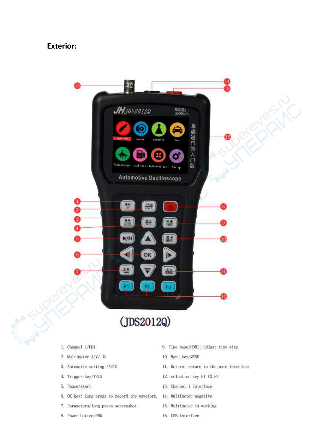
Exterior:............................................................................................................................. 3
Main interface:.................................................................................................................. 4
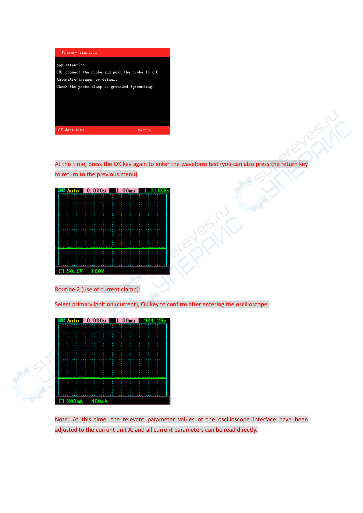
ignition: ............................................................................................................................. 4
sensor:............................................................................................................................... 6
Actuator: ........................................................................................................................... 7
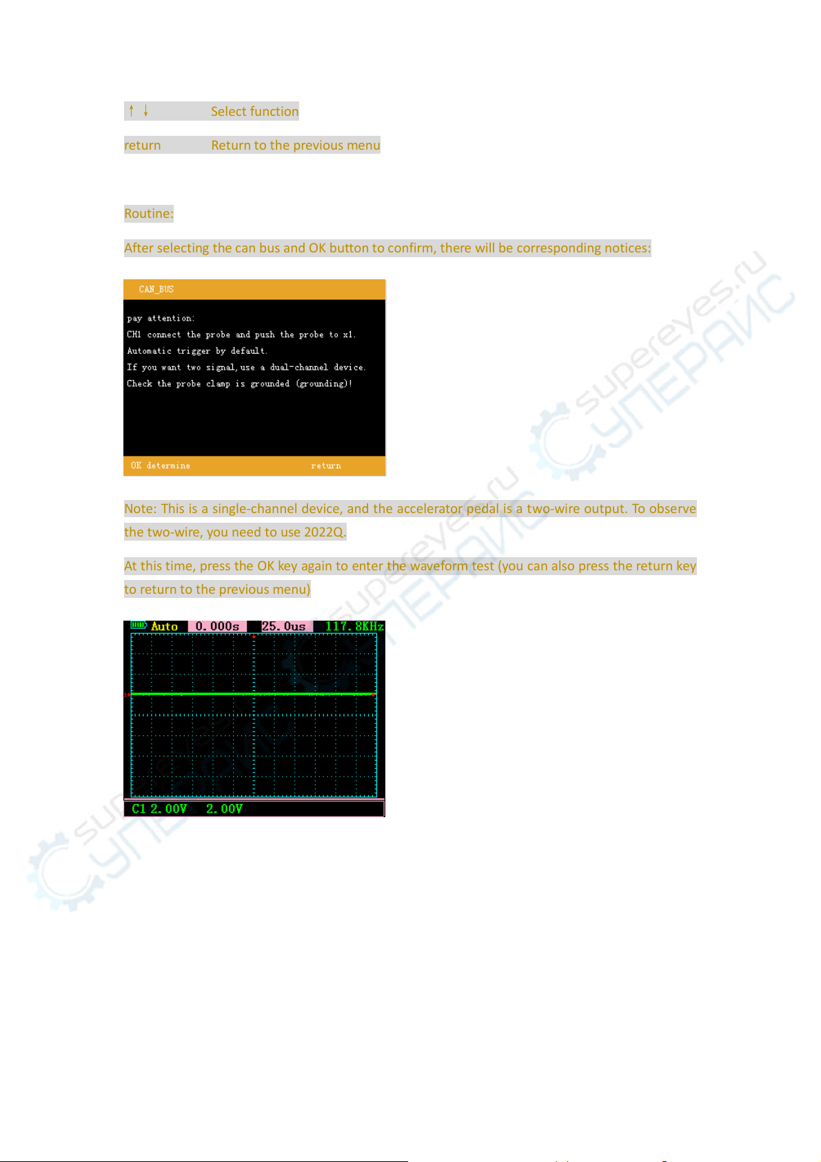
bus:.................................................................................................................................... 8
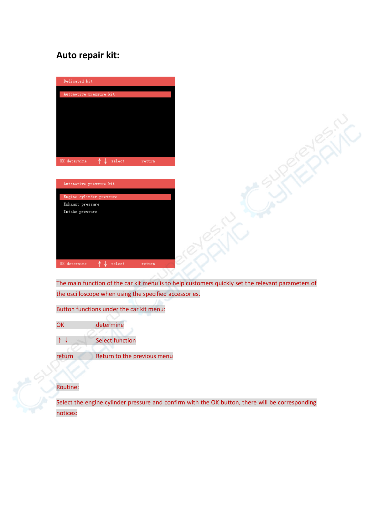
Auto repair kit: ................................................................................................................ 10
Load test:......................................................................................................................... 11
Oscilloscope: ................................................................................................................... 12
Channel 1: ............................................................................................................... 13
TRIG:........................................................................................................................ 14
HORI ........................................................................................................................ 15
Ruler:....................................................................................................................... 15
MENU ...................................................................................................................... 16
Factory reset and self-calibration:........................................................................... 17
Parameter display:................................................................................................... 18
multimeter: ..................................................................................................................... 19
Set up: ............................................................................................................................. 20
Smart trigger: .......................................................................................................... 20
Screenshot preview:................................................................................................ 20
Waveform browsing: ............................................................................................... 21
Parameter Description: ................................................................................................... 22

Exterior:

Main interface:
Boot into the main interface, you can use different functions through each submenu.
ignition:
The main function of the ignition menu is to help customers quickly set the commonly used
ignition signal parameters of the oscilloscope.
Button function under ignition menu:
OK determine
↑↓ Select function
return Return to the previous menu
Routine1:
Select the primary ignition, after the OK button is confirmed, there will be corresponding notices:

At this time, press the OK key again to enter the waveform test (you can also press the return key
to return to the previous menu)
Routine 2 (use of current clamp):
Select primary ignition (current), OK key to confirm after entering the oscilloscope:
Note: At this time, the relevant parameter values of the oscilloscope interface have been
adjusted to the current unit A, and all current parameters can be read directly.

sensor:
The main function of the sensor menu is to help customers quickly set the commonly used sensor
signal parameters of the oscilloscope.
Button function under sensor menu:
OK determine
↑↓ Select function
return Return to the previous menu
Routine:
Select the sliding resistance type of the accelerator pedal, after the OK button is confirmed, there
will be corresponding notices:
Note: This is a single-channel device, and the accelerator pedal is a two-wire output. To observe
the two-wire, you need to use 2022Q.
At this time, press the OK key again to enter the waveform test (you can also press the return key
to return to the previous menu)

Actuator:
The main function of the actuator menu is to help customers quickly set the commonly used
actuator signal parameters of the oscilloscope.
Button function under the actuator menu:
OK determine
↑↓ Select function
Return Return to the previous menu
Routine:
Select the solenoid valve, after the OK button is confirmed, there will be corresponding notices:

At this time, press the OK key again to enter the waveform test (you can also press the return key
to return to the previous menu)
bus:
The main function of the bus menu is to help customers quickly set the commonly used bus
signal parameters of the oscilloscope.
Button function under bus menu:
OK determine

↑↓ Select function
return Return to the previous menu
Routine:
After selecting the can bus and OK button to confirm, there will be corresponding notices:
Note: This is a single-channel device, and the accelerator pedal is a tw o-wire output. To observe
the two-wire, you need to use 2022Q.
At this time, press the OK key again to enter the waveform test (you can also press the return key
to return to the previous menu)

Auto repair kit:
The main function of the car kit menu is to help customers quickly set the relevant parameters of
the oscilloscope when using the specified accessories.
Button functions under the car kit menu:
OK determine
↑↓ Select function
return Return to the previous menu
Routine:
Select the engine cylinder pressure and confirm with the OK button, there will be corresponding
notices:

At this time, press the OK key again to enter the waveform test (you can also press the return key
to return to the previous menu)
Note: At this time, the relevant parameter values of the oscilloscope interface have been
adjusted to the pressure unit Bar, and all pressure parameters can be directly read.
Load test:
Car load test is mainly to test the car circuit, whether the power supply is sufficient under the
condition of heavy load.
Check whether the power supply of the car circuit is normal.

Use the multimeter pen to carry the positive and negative ends of the power cord.
If the power supply meets the current responsible demand, the buzzer will beep for a long time
and the green text will be displayed at the same time.
If the power supply cannot meet the current demand, the buzzer will alarm and flash red letters.
Oscilloscope:
After selecting the oscilloscope in the main menu, you will enter the custom oscilloscope
interface.

The function buttons of the oscilloscope are classified as follows:
Channel 1:
Press the channel 1 button to enter the channel menu.
Under the channel 1 button, the function keys have the following functions:
F1 Channel 1 display switch
F2 Unit number x1, x10, x100 selection
F3 AC/DC coupling options
OK Save reference waveform when reference waveform A and B are open
←CH1 mobile
→CH1 mobile
↑CH1 Gear adjustment
↓CH1 Gear adjustment
Press the channel 1 button again to enter the channel unit display menu:

Under the channel 1 button, the function keys have the following functions:
F1 Channel 1 unit selection (voltage, current, pressure)
F2 invalid
F3 invalid
OK Save reference waveform when reference waveform A and B are open
←CH1 mobile
→CH1 mobile
↑CH1 Gear adjustment
↓CH1 Gear adjustment
TRIG:
Press the TRIG-MATH key for the first time to enter the trigger menu.
Under the trigger menu, the function keys have the following functions:
F1 Rising edge and falling edge trigger selection
F2 Select triggerCH1

F3 Select automatic trigger, normal trigger or single trigger
OK Save reference waveform when reference waveform A and B are open
←Trigger movement (when smart trigger is off)
→Trigger movement (when smart trigger is off)
↑invalid
↓invalid
HORI
Press the time base key to enter the following menu:
Under the time base menu, the function keys have the following functions:
F1 Whether the ruler is displayed
F2 The object of the ruler isCH1
F3 The unit of the ruler (time, voltage or current or pressure)
OK Save reference waveform when reference waveform A and B are open
←Trigger reference point movement
→Trigger reference point movement
↑Time base adjustment
↓Time base adjustment
Ruler:
In the time base menu, choose to open the cursor, and you will enter the ruler menu:

The upper foot of the interface will display the parameters of scale 1, 2
Under the time base menu, the function keys have the following functions:
F1 Whether the ruler is displayed
F2 The object of the ruler isCH1
F3 The unit of the ruler (time, voltage or current or pressure)
OK Save reference waveform when reference waveform A and B are open
←Ruler 1 moves
→Ruler 1 moves
↑Ruler 2 moves
↓Ruler 2 moves
MENU
Press the menu key for the first time to enter the following interface.
Under the menu, the function key functions are as follows:
F1 Reference waveform A or B

F2 Reference waveform saveCH1
F3 Whether reference waveform A or B is open
OK Save reference waveform when reference waveform A and B are open
←invalid
→invalid
↑invalid
↓invalid
Press the menu button for the second time to enter the following interface.
Under the menu, the function key functions are as follows:
F1 Enter the factory reset menu
F2 CH1 Whether the waveform is inverted
F3 invalid
OK Save reference waveform when reference waveform A and B are open
←invalid
→invalid
↑invalid
↓invalid
Factory reset and self-calibration:
Select factory reset in the menu and enter the following menu.

Under the menu, the function key functions are as follows:
F1 invalid
F2 Self-calibration
F3 Confirm factory reset
OK Save reference waveform when reference waveform A and B are open
←invalid
→invalid
↑invalid
↓invalid
(Note: Do not connect to any external equipment during self-calibration to ensure that the
channel is disconnected!)
Parameter display:
Press the parameter key, the parameters of each channel will be displayed in the upper right
corner of the screen:

Vmin Minimum voltage (will be displayed as the unit of the relevant channel changes, current,
pressure)
Vmax Maximum voltage (will be displayed as the unit of the relevant channel changes,
current, pressure)
VPP Amplitude value (will be displayed as the unit of the relevant channel changes, current,
pressure)
PWM Duty cycle
multimeter:
F1 Select DC voltage or AC voltage
F2 Choose resistor or diode
F3 Choose on-off or capacitance
←invalid
→invalid
↑invalid
↓invalid

Set up:
Setting options description:
Language Currently supports 5 languages (Chinese, English, Russian, Spanish,
Portuguese)
sound Choose to turn on or off the key sound
Backlight Screen brightness adjustment 1-5 levels
Smart trigger Turn smart trigger on or off
Screenshot preview View the previous screenshot locally
Waveform browsing View the previously saved waveform locally
Smart trigger:
When the smart trigger is turned on, in the oscilloscope, when the waveform meets the
trigger condition, the trigger arrow will automatically find the appropriate trigger point and
trigger. It saves the manual adjustment step.
This function is only valid in automatic trigger mode, normal trigger and single trigger do not
support this function!
Screenshot preview:
This device supports one-click capture of the current screen.
Table of contents
Other Jinhan Test Equipment manuals