Hella Gutmann CSC-Kit Radar I User manual

.
BD0059V0002EN0416SO
460 985-52 / 04.16
Operating Instructions en
CSC-Kit Radar I

Inhaltsverzei hnis CSC-Kit Radar I
Table of Contents
1 Safety Notes ..................................................................................... 3
1.1 General Safety Precautions ...........................................................3
1.2 Safety Precautions for the CSC-Kit Radar I....................................3
1.3 Safety Precautions – Risk of In ury................................................4
1.4 Safety Precautions – Laser............................................................4
1.5 Safety Precautions for the Electromagnet .....................................4
2 Product Description .......................................................................5
2.1 Intended Use.................................................................................5
2.2 Delivery contents ..........................................................................5
2.3 Tool Description ............................................................................7
3 Working with the CSC-Kit Radar I .........................................10
3.1 Precondition for the Use of the CSC-Kit Radar I...........................10
3.2 Calibrating the Radar Sensor without Magnetic Laser..................10
3.3 Calibrating the Radar Sensor with Magnetic Laser.......................11
4 General Information.....................................................................15
4.1 Care and Maintenance.................................................................15
4.2 Disposal......................................................................................15
4.3 Technical Data of the Magnetic Laser ..........................................16
2

CSC-Kit Radar I Safety Notes
General Safety Pre autions
1 Safety Notes
1.1 General Safety Precautions
• The CSC-Kit Radar I is ex lusively intended for use on a
vehi le. It is a pre ondition for the use of the CSC-Kit
Radar I that the user has knowledge of automotive
te hnology and is therefore aware of the sour es of
danger and risks in the repair shop and on motor
vehi les.
• All notes given in the individual se tions of the operating
instru tions apply. The following measures and safety
pre autions must also be followed.
• Furthermore, all general requirements and standards of
supervisory bodies, trade asso iations and vehi le
manufa turers as well as all laws, regulations and odes
of ondu t to whi h a servi e workshop is subje t must
be observed.
1. Safety Precautions for the CSC-Kit Radar I
In order to avoid in orre t handling and injury to the user or
destru tion of the CSC-Kit Radar I arising from this, pay
attention to the following:
• Prote t the CSC-Kit Radar I from long periods of exposure
to solar radiation.
• Prote t the CSC-Kit Radar I from water (it is not
waterproof).
• Prote t the CSC-Kit Radar I from strong impa ts (do not
drop).
• Regularly servi e the CSC-Kit Radar I.
3

Safety Notes CSC-Kit Radar I
Safety Pre autions – Risk of Injury
1.3 Safety Precautions – Risk of Injury
When working on the vehi le, there is a risk of injury due to
rolling of the vehi le. The following must therefore be
observed:
• Prevent the vehi le from rolling.
• Additionally pla e sele tor lever of automati
transmission vehi les to P position.
1.4 Safety Precautions – Laser
There is a risk of injury through dazzling the eyes when
working with the laser. The following must therefore be
observed:
• Do not dire t the laser beam towards persons, doors or
windows.
• Never look dire tly into the laser beam.
• Ensure proper room illumination.
• Avoid trip hazards.
• Se ure me hani al parts from falling over or be oming
loose.
1.5 Safety Precautions for the Electromagnet
During the work with the ele tromagnet there is a risk of
injury through pin hing and influen e of magneti fields for e.
g. pa emakers, magneti data arriers and ele troni devi es.
Therefore regard the following:
• Carefully atta h the ele tromagnet to the angular
adjustment plate in order to prevent pin hing.
• Do not leave magenti tools about the solenoid.
• Persons with a pa emaker are allowed to use the
ele tromagnet only with prior do tor's advi e.
• Keep magneti data arriers and ele troni devi es away
from the ele tromagnet.
4

CSC-Kit Radar I Produ t Des ription
Intended Use
Product Description
.1 Intended Use
The a tive ruise ontrol system is a driver assist system offering
following advantages:
• Vehi le in front registered
• Speed of vehi le in front determined
• Requested distan e kept through engagement of engine and brakes
The CSC-Kit Radar I enables brand-spe ifi adjustments of all kinds of
systems. Therefore, in onne tion with a diagnosti tool of Hella Gutmann
you are able to alibrate e.g. the radar sensor or the amera for adaptive
headlights.
The CSC-Kit Radar I an be ex lusively operated in ombination with a
Hella Gutmann diagnosti tool. Diagnosti tools from other manufa turers
will not be supported.
. Delivery contents
QQuuaannttiittyy DDeessiiggnnaattiioonn
1CSC-Kit Radar I (optional)
Angular adjustment plate
1CSC-Kit Radar I (optional)
Magneti laser
1CSC-Kit Radar II (optional)
The entring ring for the Mer edes E-
Class an be used for this vehi le type
only.
5

Produ t Des ription CSC-Kit Radar I
Delivery ontents
QQuuaannttiittyy DDeessiiggnnaattiioonn
1CSC-Kit Radar II (optional)
The entring ring for vehi les from MY
2004 on an be used for the following
vehi le types:
• Vehi les of model year 2004-
• Commer ial vans
• EVO
• Buses of model year 2005-
4Binding head s rews
1CSC-Kit Radar II (optional)
Mirror adjustment devi e with va uum
bell (optional)
1CSC-Kit Radar II (optional)
Manual va uum pump with va uum
hose (optional)
1CSC-Kit Radar II (optional)
Nut driver 3.0 mm for repla ing the
entring ring (optional)
1CSC-Kit Radar II (optional)
Hex so ket s rewdriver 3.5 mm for
adjusting the radar sensor (optional)
1CSC-Kit Radar II (optional)
Vaseline (optional)
1CSC-Kit Radar II (optional)
Casing (optional)
1Operating and installation instru tions
6

CSC-Kit Radar I Produ t Des ription
Tool Des ription
. .1 Checking Delivery Contents
Please he k the delivery ontents upon re eiving your tool so that
omplaints an be issued immediately regarding potential damage or
missing parts.
To he k the delivery ontents:
1. Che k the pa kage delivered to ensure that it is not damaged.
Should you identify any damage to the pa kage, then open the pa kage
in the presen e of the delivery servi e and he k the CSC-Kit Radar I
for hidden damage. Any transport damage to the pa kage supplied and
damage to the CSC-Kit Radar I shall be registered in a damage report
by the delivery servi e.
2. Open the pa kage supplied and he k for ompleteness based on the
delivery note.
3. Remove the CSC-Kit Radar I from the pa kaging.
4. Che k the CSC-Kit Radar I for damage and ompleteness.
.3 Tool Description
.3.1 Angular adjustment plate
7

Produ t Des ription CSC-Kit Radar I
Tool Des ription
Designation
1Angular ad ustment plate
2Level gauge
Here you an he k whether the angular adjustment
plate is atta hed in the exa t horizontal position.
3Attachment bracket of cross member
Here the angular adjustment plate an be atta hed to
the ross member.
4Attachment positions 1, 2 and 3
Depending on the vehi le manufa turer, a variety of
atta hment positions must be observed here. They
are des ribed
.3. Magnetic Laser
Designation
1Output of the laser beam/laser beam
Output of laser beam. Use the laser beam to read the
a tual value at the s ale of the magneti laser.
2Switch
Swit h the laser on and off.
3 Lever
Swit h the ele tromagnet on and off.
4 Battery compartment cover
Insert two batteries type AA here.
8

CSC-Kit Radar I Produ t Des ription
Tool Des ription
Designation
5Electromagnet
Here you an fasten the magneti laser to the angular
adjustment plate.
6Level gauge
Here you an he k whether the magneti laser is
atta hed in the exa t horizontal position.
.3.3 Replacing the Batteries
Replacing the Type AA Batteries
Pro eed as follows to repla e the batteries:
1. Swit h off the laser beam (1) with the swit h (2).
2. Remove the battery ompartment over (4), tilting it from the bottom
side towards the top.
3. Remove the batteries individually.
NOTE
Pay attention to orre t installation dire tion/polarity.
4. Reassembly in reverse order
9

Working with the CSC-Kit Radar I CSC-Kit Radar I
Pre ondition for the Use of the CSC-Kit Radar I
3 Working with the CSC-Kit Radar I
The following steps are ne essary to work with the CSC-Kit Radar I:
1. Pla e the CSC Panel in front of the vehi le (see operating instru tions
of CSC-Tool).
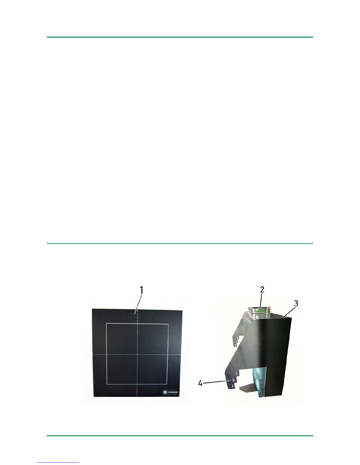
2. Atta h the angular adjustment plate to the ross member.
3. Fix the magneti laser onto the angular adjustment plate where
ne essary.
4. Fix the CSC-Kit Radar II to the radar sensor where ne essary.
The steps are des ribed below.
3.1 Precondition for the Use of the CSC-Kit Radar I
Regard the following in order to use the CSC-Kit Radar I:
• Vehi le system is working properly
• No trouble odes stored in the ECU
• Possible vehi le-spe ifi preparations done
• Rear axle tra k adjusted properly
• Horizontal position of the vehi le on even surfa e ensured
• Vehi le front removed where ne essary
• CSC-Tool with CSC-Kit Radar I orre tly pla ed in front of the vehi le
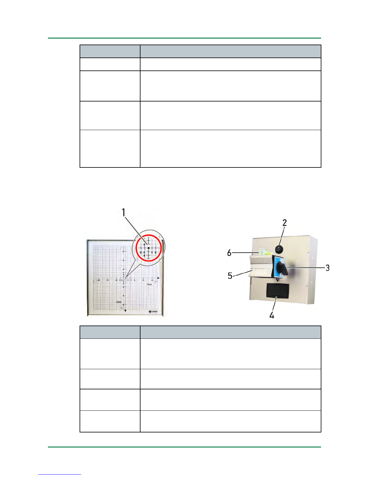
• Level gauge bubble of angular adjustment plate entered
3. Calibrating the Radar Sensor without Magnetic Laser
Depending on manufa turer, model and year of manufa ture, the radar
sensor an be alibrated without the magneti laser. The tool indi ates a
orresponding note.
Pro eed as follows to alibrate the radar sensor without the magneti
laser:
1. Conne t the diagnosti tool to the vehi le (see user manual).
2. Sele t >Diagnostics< in the main menu.
3. Sele t the system to be alibrated under >Basic settings<.
10

CSC-Kit Radar I Working with the CSC-Kit Radar I
Calibrating the Radar Sensor with Magneti Laser
4. Observe the info and instru tions window.
CAUTION
Danger of injury or pin hing through heavy parts
The angular adjustment plate may drop when fixing it to
the ross member and may ause injuries.
Ask a se ond person to fix the angular adjustment plate to
the ross member.
5. Atta h the angular adjustment plate (1) to the ross member as shown
in the tool.
The angular adjustment plate must be within the radar sensor area.
The level gauge bubble must be entered.
6. Follow the on-s reen instru tions.
The radar sensor an be alibrated now.
3.3 Calibrating the Radar Sensor with Magnetic Laser
Depending on manufa turer, model and year of manufa ture, the radar
sensor must be alibrated with the magneti laser.
Pro eed as follows to alibrate the radar sensor with the magneti laser:
1. Conne t the diagnosti tool to the vehi le (see user manual).
2. Sele t >Diagnostics< in the main menu.
11

Working with the CSC-Kit Radar I CSC-Kit Radar I
Calibrating the Radar Sensor with Magneti Laser
3. Sele t the system to be alibrated under >Basic settings<.
A window with information and instru tions appears.
CAUTION
Danger of injury or pin hing through heavy parts
The angular adjustment plate may drop when fixing it to
the ross member and may ause injuries.
Ask a se ond person to fix the angular adjustment plate to
the ross member.
4. Atta h the angular adjustment plate (1) to the ross member in
position 2.
The angular adjustment plate must be within the radar sensor area.
Depending on the sele ted manufa turer and vehi le type, the CSC-Kit
Radar II must be atta hed to the radar sensor.
5. Fix the CSC-Kit Radar II to the radar sensor (see assembly instru tions
CSC-Kit Radar II) where ne essary.
12

CSC-Kit Radar I Working with the CSC-Kit Radar I
Calibrating the Radar Sensor with Magneti Laser
6. Turn the lever (3) at the magneti laser of the ele tromagnet (5) to the
left to ON.
The ele tromagnet is a tivated and the magneti laser an be fixed
onto the angular adjustment plate.
CAUTION
Laser radiation
Damage to/destru tion of the retina
Never look dire tly into the laser beam.
7. Swit h on the laser beam (1) with the swit h (2) at the magneti laser.
8. Fix the magneti laser onto the angular adjustment plate (1).
The magneti laser must be within the radar sensor area.
13

Working with the CSC-Kit Radar I CSC-Kit Radar I
Calibrating the Radar Sensor with Magneti Laser
9. Dire t the laser beam (1) at the magneti laser entred to the mirror of
the radar sensor.
The laser beam will be refle ted from the mirror to the s ale of the
magneti laser.
10. Dire t the horizontal and verti al level gauge (6) by shifting the
magneti laser.
The radar sensor an be alibrated if the horizontal and verti al level
gauge bubbles are entered.
11. Observe the info and instru tions window.
12. Follow the on-s reen instru tions.
The radar sensor an be alibrated now.
13. Swit h off the laser beam (1) with the swit h (2) at the magneti laser
after having the radar sensor alibrated.
The laser beam is swit hed off.
14

CSC-Kit Radar I General Information
Care and Maintenan e
4 General Information
4.1 Care and Maintenance
As with every tool, the CSC-Kit Radar I should also be handled with are.
• Regularly lubri ate moving parts with a id-free and resin-free grease
or oil.
• Re-tighten the mounting bolts regularly.
• Regularly lean the CSC-Kit Radar I with non-aggressive leaning
agents.
• Use ommer ial household leaning detergents and a moistened, soft
leaning loth.
• Repla e damaged a essories immediately.
• Always use original spare parts.
4. Disposal
NOTE
The guidelines listed here are ex lusively valid within the
European Union.
In omplian e with dire tive 2012/19/EU of the European Parliament and
Coun il dated 04. Juli 2012, relating to Waste Ele tri al and Ele troni
Equipment (WEEE), and the German national statute governing the
distribution, return and environmental disposal of ele tri al and ele troni
equipment (Ele tri al and Ele troni Equipment A t – ElektroG) dated 16
Mar h 2005, we are obliged to take ba k this tool, distributed after 13
August 2005, at the end of its servi e life and to dispose it in a ordan e
with the above mentioned regulations.
Be ause this tool is used ex lusively for industrial purposes (B2B), it must
not be handed over to a publi disposal fa ility.
The tool an be disposed of at the following address (spe ifying the date of
pur hase and the tool numbers):
Hella Gutmann Solutions GmbH
Am Krebsba h 2
79241 Ihringen
15

General Information CSC-Kit Radar I
Te hni al Data of the Magneti Laser
GERMANY
WEEE reg. no.: DE 25419042
Phone: +49 7668 9900-0
Fax: +49 7668 9900-3999
Mail: info@hella-gutmann. om
NOTE
Batteries ontain toxi substan es. Therefore, do not throw
used batteries into household waste but dispose of them
properly.
The batteries an also be sent to Hella Gutmann for disposal
free of harge.
4.3 Technical Data of the Magnetic Laser
4.3.1 General Data
Ambient temperature Re ommended: 0 to 35 °C
Working area: 0 to 50 °C
Supply voltage 2.7 to 3.3 VDC
Batteries 2x 1.5 V AA
4.3. Laser
Wavelength 650 Nm
Output 1 mW
Class 2
Operating range 3.4 m
4.3.3 Electromagnet
Wavelength 670 Nm
Output 1 mW
16

CSC-Kit Radar I General Information
Te hni al Data of the Magneti Laser
Class 2
Operating range 5 m
17

Notes CSC-Kit Radar I
Notes
18

CSC-Kit Radar I Notes
Notes
19

HELLA GUTMANN SOLUTIONS GMBH
Am Krebsba h 2
79241 Ihringen
GERMANY
Phone: +49 7668 9900–0
Fax: +49 7668 9900–3999
info@hella-gutmann. om
www.hella-gutmann. om
© 2016 HELLA GUTMANN SOLUTIONS GMBH
1 STUECK/PIECE(S)
*9XQ 460 985-521*
9XQ 460 985-521
Made in Ger any
Table of contents
Other Hella Gutmann Test Equipment manuals

Hella Gutmann
Hella Gutmann mega macs PC User manual

Hella Gutmann
Hella Gutmann CSC-Kit Radar II User manual

Hella Gutmann
Hella Gutmann SEG Series Manual

Hella Gutmann
Hella Gutmann BMA-Tool User manual

Hella Gutmann
Hella Gutmann Radar Kit III User manual

Hella Gutmann
Hella Gutmann SEG IV User manual

Hella Gutmann
Hella Gutmann CSC-Tool User manual

Hella Gutmann
Hella Gutmann CSC-Tool User manual

Hella Gutmann
Hella Gutmann SEG V User manual

Hella Gutmann
Hella Gutmann CSC-Tool SE User manual