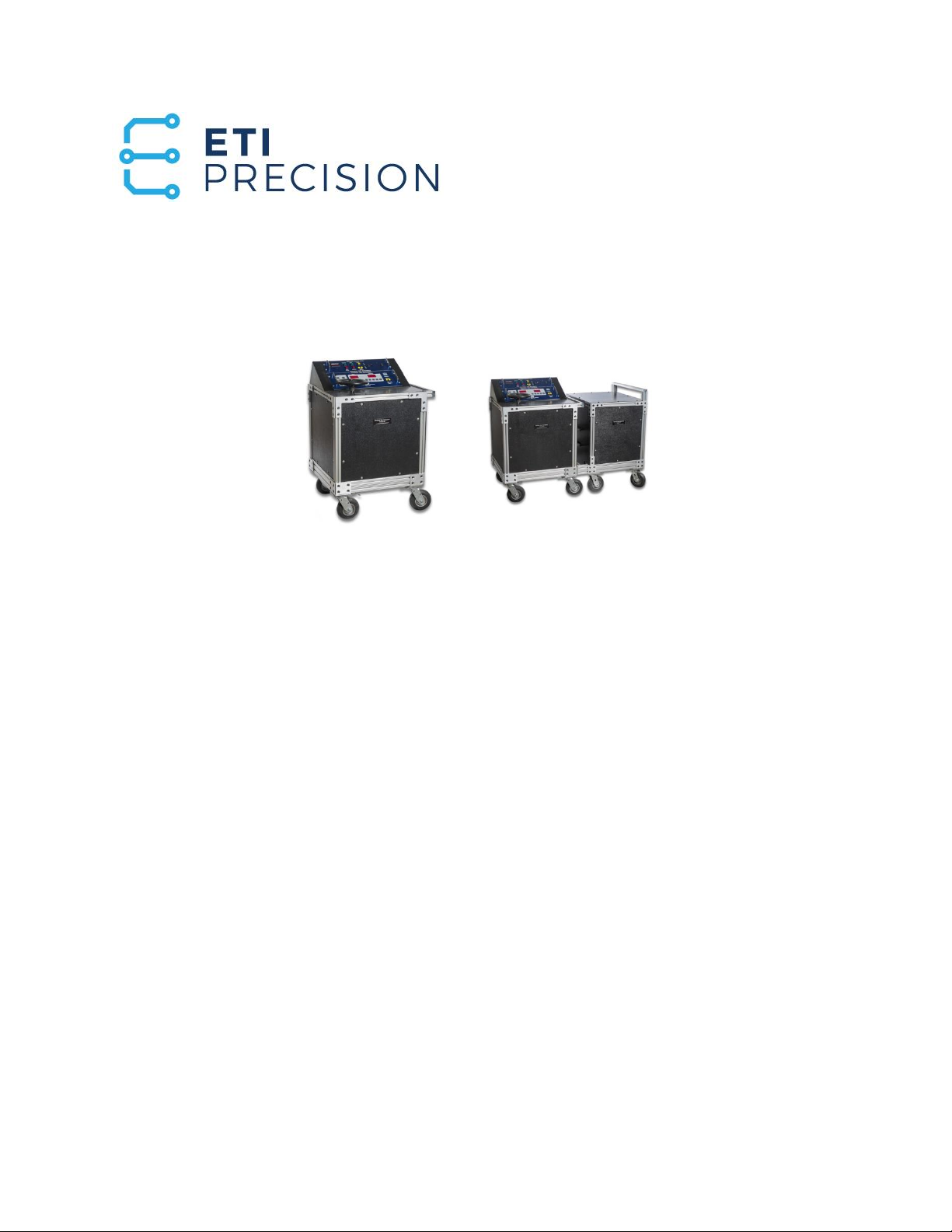
Electrical Test Instruments PI-2500 & PI-5000
Section II - Detailed Description
==============================================================================
==============================================================================
Copyright(C) 1994-2008 Electrical Test Instruments, LLC. All Rights Reserved
Page II-3
The test set may be plugged into any 60 Hz AC voltage source of 200-250 VAC
or 400-500 VAC, and will work on 50 Hz sources of 200-210 VAC or 400-420 VAC.
The line voltage is displayed on the indicator control panel digital meter. An in-
put selector switch can be set for 208, 240, or 480 VAC inputs. An internal volt-
age sensor automatically ensures that the switch is set correctly before AC con-
trol power can be turned on, and monitors input voltage for compliance to spec-
ifications.
The Vernier uses a large wheel to adjust the output manually within the range
determined by the coarse tap, as well as a motorized control actuated by means
of a smart control switch. When the switch is pressed briefly, the Vernier moves
in a very small increment for fine control. When the switch is held, the Vernier
moves very quickly, so that the entire span may be traversed in less than five
seconds. The approximate Vernier position is displayed on an LED indicator bar
graph. For the PI-2500, the Vernier is always turned clockwise to increase out-
put.
The electronically controlled tap selection uses power contactors to set the
coarse tap. The unit powers up in the lowest tap position (1), and the setting may
be adjusted by means of a rocker switch on the indicator/control panel. If the
switch is held, the taps change at a rate of about two seconds per tap. Tap
change is not allowed when output is on. Note: Output taps 1-3 only for the PI-
2500. Output taps 4-9 are only operational when the AUX-5000 section is con-
nected to the PI-2500 section.
The indicator/control panel features two temperature indicators: one for the
output bus temperature, and the other for the overall system temperature. This
is determined by a combination of actual winding temperature, and a “virtual
temperature” which is derived from time and current duty cycle usage as mon-
itored by a “POD”, or Programmable Overload Device. Additional details are
available in a separate manual. If either temperature exceeds a safe operating
level, the interlock is asserted, and the output section is de-energized. Addi-
tional thermostatic sensors in the output transformer windings will also assert
the interlock if unsafe temperature levels are detected.
The output voltage of the test set is provided on the indicator/control panel for
monitoring by means of a separate digital voltmeter.
Primary catastrophic overload protection for the test set is accomplished with
input fuses having high interrupting current capacity. Overload of the output
system is sensed by means of the previously mentioned “POD” on the Vernier
autotransformer, and thermal sensors in the transformer winding. Thermal
switches are also installed in the transformer windings. The combination of
these devices allows full utilization of the overload capability of the test set and
eliminates costly and cumbersome fuse replacement required in other test sets.