T&R TPT9000 Operating instructions

2
GENERAL SAFETY STATEMENT
WARNING
The following safety precautions should be reviewedto avoid injury
to the user and damage to the product (and other products
connected to it). To avoid potential hazards only use this product
as specified.
•Only suitably qualified personnel should use this
equipment. Servicing of this product should only be
carried out by suitably qualified service personnel.
To Avoid Fire Hazards and Personal Injury
•Use the fused leads supplied with the unit.
•Ensure that systems that the unit is to be connected to are
dead.
•Do not connect and disconnect leads whilst outputs are
switched on. Breaking the output circuit with current flowing
may cause arcing.
•Terminal ratings must be observed to prevent fire hazards and
risk of injury to the operator. Consult the product manual for
ratings information before making connections to any terminal.
•It is ESSENTIAL to consult the product manual for rating
information before making any connection to a terminal or
terminal group marked with a warning triangle.
•Only use fuses of a type and rating specified for this product.
•Do not operate the unit out of its case or with any covers or
panels removed.

3
•Do not touch exposed connections and components when
power is present.
•Do not operate the product if any damage is suspected. Refer
the unit to qualified service personnel to be checked.
•Do not operate the unit in wet or damp conditions.
•Do not operate the unit in an explosive atmosphere.
•Warnings from cardiac pacemaker manufacturers state that strong
magnetic fields may affect operation. The TPT9000 may induce
large magnetic fields in transformers and should therefore not be
operated by, or in the vicinity of persons fitted with cardiac
pacemakers or any other electronic or electrical medical implants.
If any further queries occur regarding the usage
and maintenance of the equipment detailed in this
manual, please refer these to the supplier of the
equipment in the first case or to the manufacturer,
T & R Test Equipment Limited.

4
SAFETY TERMS AND SYMBOLS
The following safety symbols appear on the equipment:
WARNING –Refer to manual
Test Button

5
CONTENTS
1. DESCRIPTION OF EQUIPMENT 6
1.1 Connections, controls & display 7
1.1.1 LED messages 10
1.2.1 Environment 12
1.2.2 Supply requirements 12
1.2.3 Connection cable ratings 12
1.2.3 Overload protection 12
2Theory of Operation 13
2.1 Main current output 13
3. APPLICATIONS 15
3.1 Transformer Testing 15
3.1.1 CT Testing 15
3.1.2 Transformer Testing 17
3.1.3 High Primary Impedance Transformer Testing 19
4. MAINTAINANCE 21
4.1 Replacing the Battery 21
5. STANDARD ACCESSORIES 22
5.1 Spares fuses supplied 22
5.2 Standard accessories supplied 22
5.3 Optional accessories/spares 22
6. REVISION 23

6
1. DESCRIPTION OF EQUIPMENT
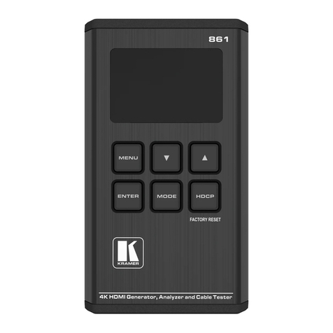
The TPT9000 is used for determining the correct polarity
of current and voltage transformers. The TPT9000
automatically detects if the transformer has been
connected incorrectly. The setalso includes a proving unit
to check the correct operation of the unit in the field.
The TPT9000 is designed to be used on ‘dead’ systems
(i.e., no externally supplied voltages are present on the
testobject). DonotconnecttheTPT9000to alivesystem.
Always check that the power to the device under test is
off and the circuit is isolated before making any
connections.

7
1.1 Connections, controls & display
Figure 1.1 TPT9000

8
Ref
Item
Function
A
Battery Low LED
Indicates if the internal battery
voltage has dropped below a
useable level
B
Reverse LED
Indicates that the test
transformer has one winding
connected with reversed
polarity to the other
C
Brown terminal
Connect to P1 of the test
transformer
D
Blue terminal
Connect to P2 of the test
transformer
E
Black terminal
Connect to S2 of the test
transformer
F
Red terminal
Connect to S1 of the test
transformer
G
Forward LED
Indicates that both windings of
the test transformer are
connected in the same polarity
H
Error LED
Indicates that the test
transformer has not been
connected properly
I
Test button
Switches the unit on and starts
a test
J
Magnet
For securing the TPT9000 while
testing
K
Battery cover
Remove cover to replace the
battery

9
Figure 1.2 Proving Unit
Ref
Item
Function
A
Polarity Switch
Switch test polarity between
Forward and Reverse
B
Connectors
Connectors to fit the proving
unit into the TPT9000
terminals.

10
1.1.1 LED messages
Figure 1.3 Green LED 1 second flash
The Green LED will light for 1 second when the transformer under
test has been connected with both windings in the same polarity.
Figure 1.4 Red LED 1 second flash
The Red LED will light for 1 second when the transformer under
test has been connected with the windings in a different polarity.
Figure 1.5 Amber LED 1 second flash
The Amber LED light for 1 second when the TPT9000 has carried
out a test on the test transformer but no response has been
detected on the return connections. This can be caused by poor
connections to the transformer windings.

11
Figure 1.6 Rapid flashing Amber LED
The Amber LED will rapidly flash for 1 second when the TPT9000
detects that either the transformer under test has a voltage present
or that there is a connection between the Primary and Secondary
windings. Note that the TPT9000 cannot test auto transformers.
Figure 1.7 Amber LED 1 second flash
The Battery Low LED will light up for 1 second when the TPT9000
detects that the internal 9V battery voltage has dropped below a
usable level.

12
1.2 Installation
1.2.1 Environment
The TPT9000 is designed for use in industrial and
electrical substation environments.
Category Rating: CATIII
Maximum altitude: 2000m
Temperature: 0°C to 45°C operating
-20°C to 60°C storage
Relative humidity: 90% non-condensing
Protection rating: IP20 in use
1.2.2 Supply requirements
The TPT9000 requires a single PP39V battery to operate.
The battery level is automatically monitored, the device
will not perform a test if the battery voltage has dropped
below a useable level.
1.2.3 Connection cable ratings
Test Leads 600V CAT IV fused test
leads terminated in shrouded
4mm connectors.
1.2.3 Overload protection
Each of the test leads must be fitted with a F500mA HBC
fuse. This must be replaced with a fuse of the same type.

13
2 Theory of Operation
2.1 Main current output
The TPT9000 first checks that there is no connection
between the Primary and Secondary windings. Note, the
TPT9000 cannot test auto transformers.
If a connection between the windings is detected the test
will be stopped and the Amber ERROR LED will flash
rapidly.
If no connection is detected between the two windings the
TPT9000 will inject a small pulse of current into the
Primary winding.
The unit then waits for a resulting pulse on the Secondary
winding.
If the detected pulse is in the same polarity to the injected
pulse the transformer under test has been connected with
Forward polarity. The Green FORWARD LED will light for
1 second.
If the detected pulse is in the opposite polarity to the
injected pulse the transformer under test has been
connected with Revered polarity. The Red REVERSE
LED will light for 1 second.
If a return pulse is not detected the Amber ERROR LED
will light for 1 second. Check the connections to the test
object.

14
2.2 Proving Unit
The function of the TPT9000 can be checked using the
included proving unit.
Fit the proving unit into the output terminals of the
TPT9000. The switch on the front of the proving unit can
be set so that it appears as either a forward or reverse
connected transformer.
Select forward or reverse and then press the test button.
The corresponding forward, reverse or error LED will light.
Warning:
The TPT9000 is designed to test
transformers that have been disconnected
from all power supplies. Do not apply any
power to the terminals of the unit.

15
3. APPLICATIONS
This chapter describes how to use the TPT9000 to test
different types of transformers.
3.1 Transformer Testing
3.1.1 CT Testing
Figure 2.1 TPT9000 connections to a test CT
▪Check the CT for Primary polarity markings. If the
CT has been marked P1 and P2 or the direction of
the current through the CT is known, this should be
observed when connecting the TPT9000.
▪The Brown output wire from the TPT9000 must be
looped through the central hole of the CT. Pass the
wire in through the P1 side and out of the P2 side.
If the CT does not have its polarity marked but the
direction of current flow is known, pass the brown
wire through positive side of the test transformer.

16
▪Pass the wire out of the P2 side of the CT and back
to the blue terminal of the TPT9000.
▪If the polarity of the primary of the CT is not known,
loop the wire through the central hole in any
direction.
▪Check the secondary side of the CT for polarity
markings.
▪Connect the secondary terminal marked S1 to the
Red input of the TPT9000 and the secondary
terminal marked S2 to the Black input of the
TPT9000.
▪Do not touch the CT or any of the wires during the
test.
▪Press the test button on the TPT9000.
▪The TPT9000 will first test to see if the test
transformer has been connected correctly. If the
Errorled illuminatescheckall theconnectionstothe
test transformer are correct.
▪The TPT9000 will display the polarity of the current
connection to the test CT.
▪If the Forward LED lights, then the unknown side of
the test CT has been connected correctly with
respect to the known side of the test CT.
▪If the Reverse LED lights, then the unknown side of
the test CT has been connected reversed with
respect to the known side of the test CT.

17
3.1.2 Transformer Testing
Figure 2.2 TPT9000 connections to a test transformer
▪Inspect the test transformer for polarity markings.
▪In the case of the Secondary winding connections
being unknown. Connect the Primary in the correct
polarity as shown above. Connect the Brown P1
wire from the TPT9000 to the P1 terminal of the test
transformer. Connect the Blue P2 wire from the
TPT9000 to the P2 terminal of the test transformer.
▪For the unknown secondary connections connect
the Red S1 and the Black S2 wires from the
TPT9000 across the secondary winding.
▪Do not touch the test transformer or any of the wires
during the test.
▪Press the TEST button on the TPT9000.
▪The TPT9000 will display the result of the test.

18
▪A green Forward led shows that the unknown side
has been connected in the same polarity as the
known side.
▪A red Reverse led shows that the unknown side has
been connected in the opposite polarity as the
known side.
▪If the Error led flashes rapidly the TPT9000 has
detected a short circuit between the Primary and
Secondary of the test transformer. Check that the
connections to the test transformer have been
made correctly.
▪If the Error led flashes for 1 second, the TPT9000
has not detected any response from the test
transformer. Check that the connections to the test
transformer have been made correctly. If the
connections are ok but the error persists the
transformer may have a primary winding with a high
impedance. See section 3.1.3.
▪In the case of the Primary winding connections
being unknown. Connect the Secondary in the
correct polarity as shown above. Connect the Red
S1 wire from the TPT9000 to the S1 terminal of the
test transformer. Connect the Black S2 wire from
the TPT9000 to the S2 terminal of the test
transformer.
▪The test and results will be displayed as before.

19
3.1.3 High Primary Impedance Transformer Testing
Figure 2.3 TPT9000 connections to a test transformer with a high
impedance Primary winding
Some transformers have a very high primary
winding impedance. The voltage of the injected
current may be too low to energise the
transformer. Despite the test transformer being
properly connected the Amber ERROR light will
show that no return pulse has been detected. If
the secondary winding has a much lower
impedance, we can still use the TPT9000 to test
the transformer.
▪Connect the P1 high impedance terminal of the test
transformer to the Red S1 terminal of the TPT9000
and the P2 high impedance terminal of the test
transformer to the Black S2 terminal of the
TPT9000.

20
▪Connect the S1 low impedance terminal of the test
transformer to the Brown P1 terminal of the
TPT9000 and the S2 low impedance terminal of the
test transformer to the Blue P2 terminal of the
TPT9000.
▪When you press the TEST button the TPT9000 will
inject the test current into the secondary winding of
the test transformer.
▪Do not touch the test transformer or any of the wires
during the test.
▪The TPT9000 will display the result of the test.
▪The TPT9000 will first test to see if the test
transformer has been connected correctly. If the
Error led illuminates check if the connections to the
test transformer are correct.
▪A green Forward led shows that the unknown side
has been connected in the same polarity as the
known side.
▪A red Reverse led shows that the unknown side has
been connected in the opposite polarity as the
known side.
Table of contents
Other T&R Test Equipment manuals
T&R
T&R 200A-3PH mk2 Operating instructions
T&R
T&R 200A-3PH Operating instructions
T&R
T&R KV30-40 Operating instructions
T&R
T&R PT30-10 mk2 Operating instructions
T&R
T&R PT30-10 Operating instructions
T&R
T&R CU-Ps Operating instructions
T&R
T&R PCU2 mk5 Operating instructions
T&R
T&R PT18-10 mk2 Operating instructions
T&R
T&R KV30-40D mk3 Operating instructions
T&R
T&R KV mk2 Series Operating instructions

