5
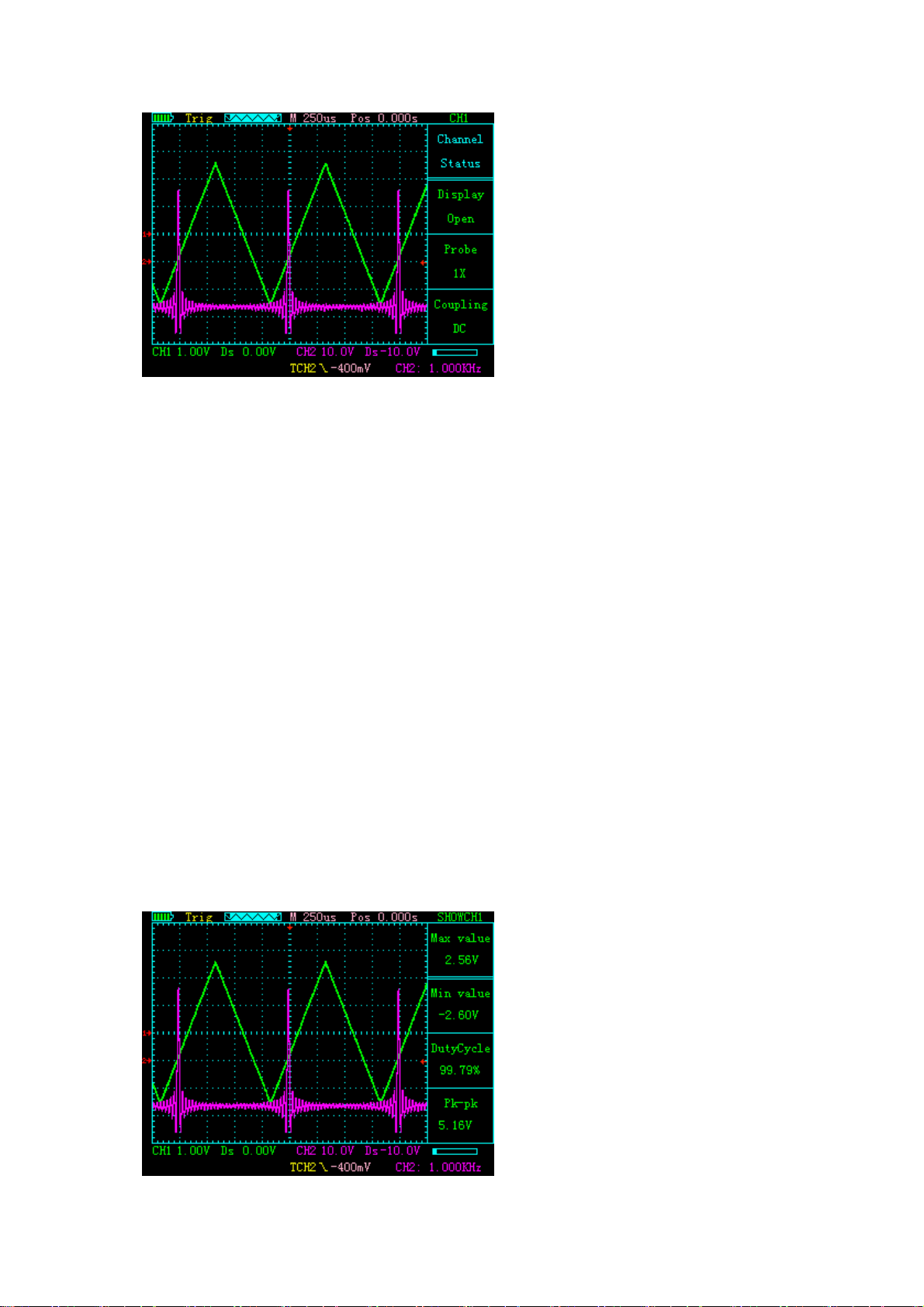
In this interface, the following buttons have the following features:
F1: invalid
F2: invalid
F3: invalid
↑: Increase the size of the channel 1 unit grid representation (5V-10mV)
↓: Reduce the size of the channel 1 unit grid representation (5V-10mV)
←:Move the channel 1 arrow down
→:Move channel 1 arrow up
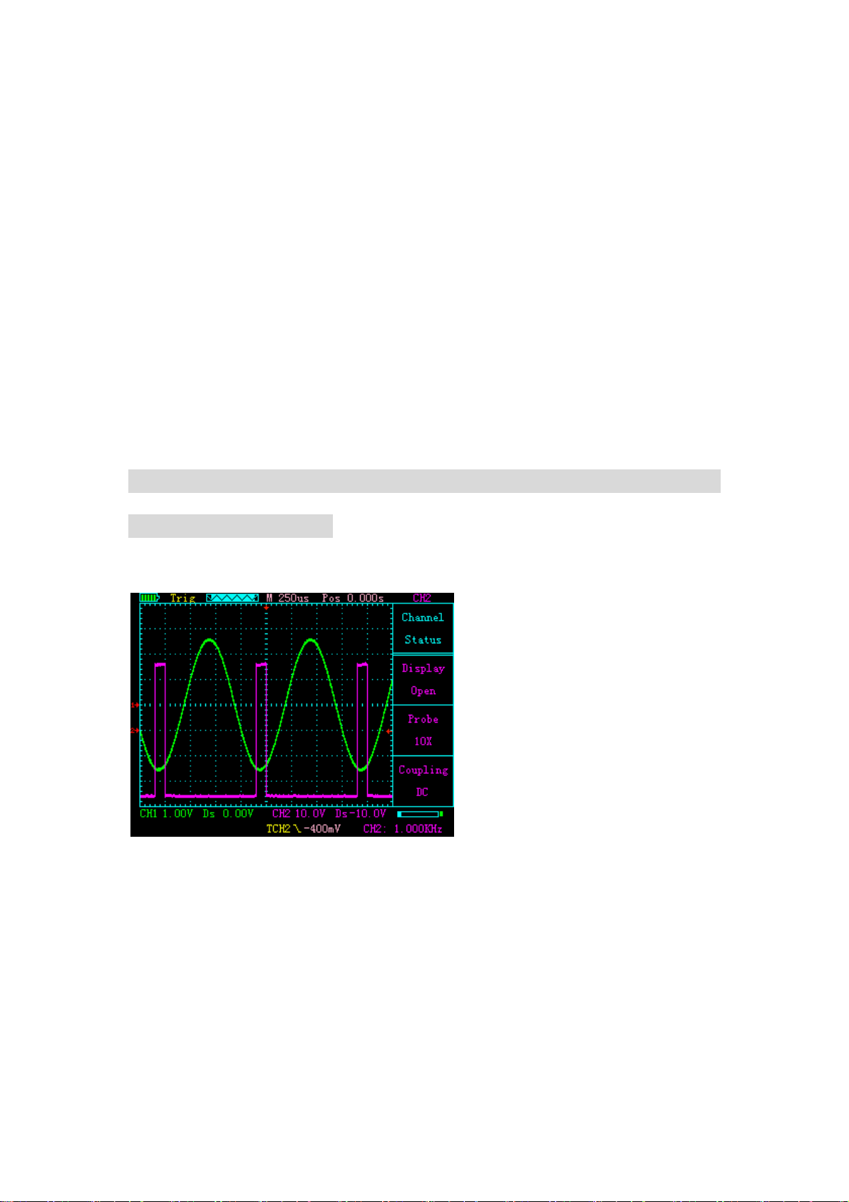
Description: The displayed parameters have maximum, minimum, duty
cycle, peak-to-peak value
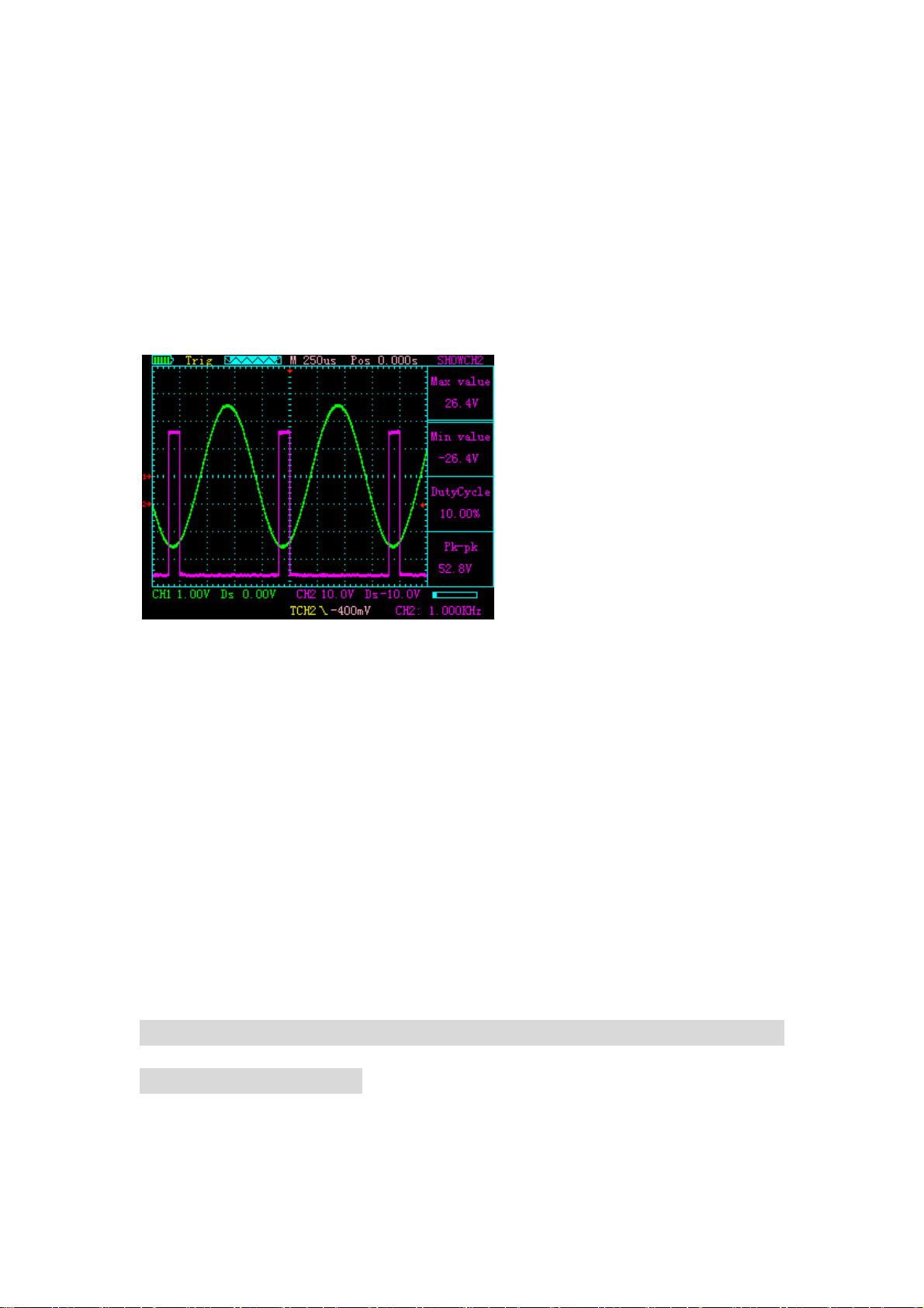
Click CH2 / PARM2 to enter the control interface of CH2
In this interface, the following buttons have the following features:
F1: Control channel 2 is displayed or turned off
F2: Select Increase of probe: x1, x10, x100
F3: Select the coupling mode of channel 1 as DC or AC
↑: Increase the size of the channel 2 unit grid representation
(5V-10mV)