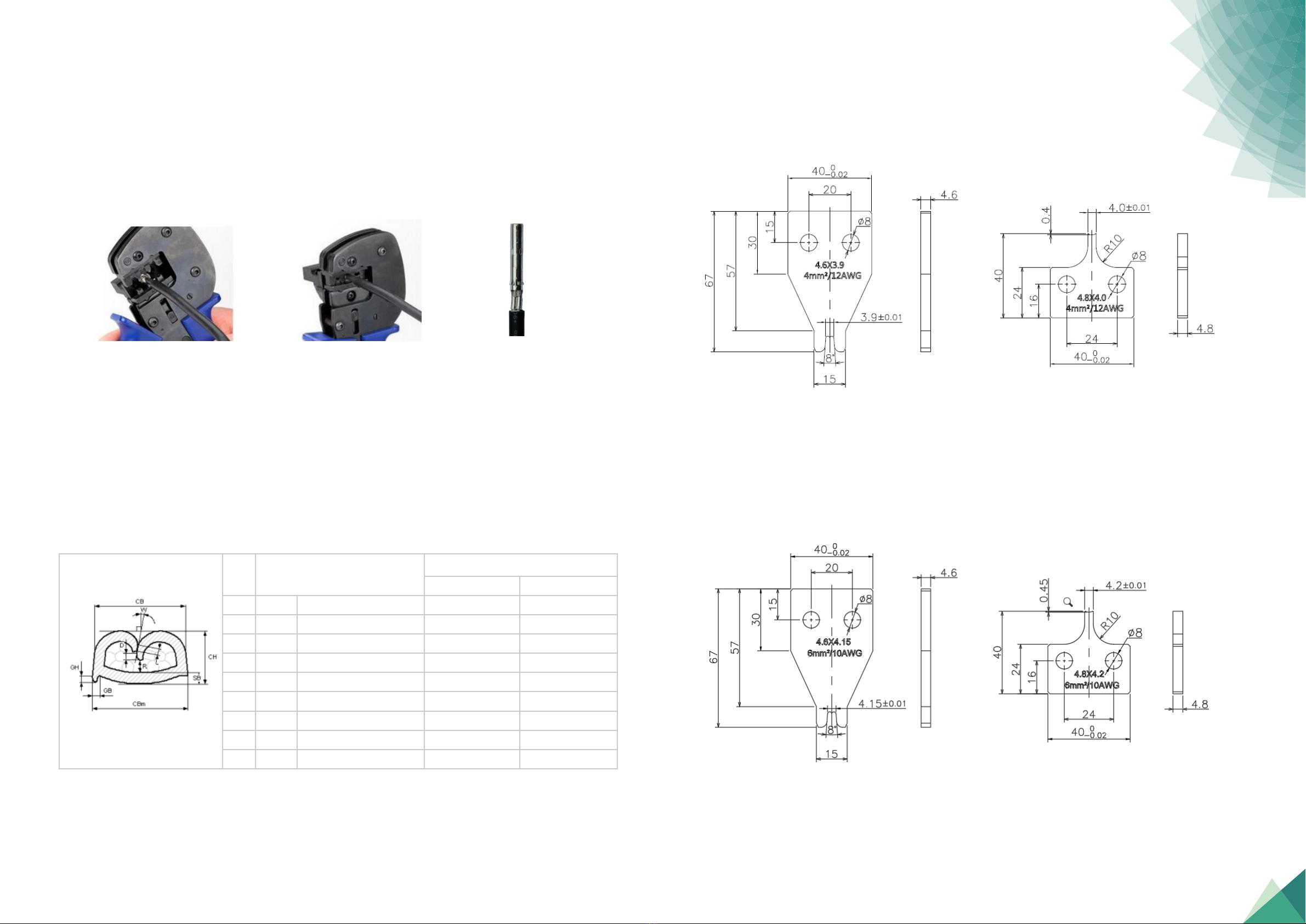
3.Technical Data 4.Tools Instruction
JKT-01:2.5mm²(14AWG)、4.0mm²(12AWG)、6.0mm²(10AWG)
The Stripping Tool-JKT-01 is applicable to 2.5mm²(14AWG) or 4.0mm²(12AWG) or
6.0mm²(10AWG) cable.
There is one stripping tool JKT-01 per tool set.
Function: Cutting the wire insulation (exposing the copper wire).
JKT-02:2.5mm²(14AWG)、4.0mm²(12AWG)、6mm²(10AWG)
The Crimping Tool-JKT-02 is applicable to 2.5mm²(14AWG) or 4.0mm²(12AWG) or 6.0mm²
(10AWG) cable.
There is one crimping tool-JKT-02 per tool set.
Function: The connection and crimping between the copper wire and metal terminals are
all made by the crimping tool.
Type Name or Model No.
Rated Voltage ( V DC)
PV-JK03M2-F/xy, PV-JK03M2-M/xy
1500 V DC
Rated Insulation Voltage
Rated Current (A DC)
Application Class Class A
Protection Class / Pollution Degree Class II / 2
Ambient Temperature -40℃to +85℃
Upper Limit Temperature 115℃
Over Voltage Category CAT III
Flammability Class
Degree of Protection, mated / unmated
UL94 V-0
Rewireable No
Cable Diameter 4.7mm to 8.0mm
Contact Resistance ≤ 0.2 m Ω
Contact material Copper, tin plated
Insulation Material PA
Existence of an enclosure Enclosed connector
Certification Standard IEC 62852 Edition 1.0 2014-11;
UL6703
IP65/ IP68 (1m, 2h) in mated condition
IP2X in unmated condition
8000 V (1500 V DC)
30 A (2.5mm²/14AWG)
45 A (4.0mm²/12AWG)
50 A (6.0mm²/10AWG)
60 A (10.0mm²/8AWG)
Wire Cross Section Area or Cross
Section Range
1X2.5mm²(14AWG) for x=1;
1X4.0-6.0mm² (12AWG/10AWG) for x =2;
1X10.0mm²(8AWG) for x=3;
Note: PV-JK03M2-F/xy ; PV-JK03M2-M/xy (x=1 or 2, y=B or C)
Stripping Tool - JKT-01
Crimping Tool- JKT-02
Assembly Tool -JKT-06
JKT-06:
Assembly Tool -JKT-06:There are two assembly tools per tool set.
Function: Used for assembling and disassembling connectors.
Installation Manual for PV-JK03M2/xy Series Cable Connector | 0706