JK CFS-20 User manual

1
CFS-20 Combination Foldable Studreel & Floor Reel Instruction Manual

2
Table of Contents
Parts List……………………………………………………………………………………… 3
Assembly…………………………………………………………….…………… 5
Making Adjustments………………………………………………………………………….. 12

3
Parts List

4
Part Number
Part Name
Quantity
1
Spindle Rod
FSR-100
1
2
Hex Set–Screw Bushing
FSR-101-A
2
3
Wire Hub Arm
FSR-102
4
4
Spring
FSR-103
1
5
Wire Tray Arm Stop Washer
FSR-104
1
6
Wire Tray Arm
FSR-102
4
7
Star Hub
FSR-106-B
2
8
Small Washer
FSR-108
1
9
Arms Assembly Nut & Screw
FSR-109
12
10
Swivel Mount Assembly Weldment
FSR-110
1
11
Stud Mount Assembly Weldment
FSR-112
1
12
Wire Guide Set-Screw
FSR-115
1
13
Wire Guide
FSR-116
1
14
5/16” Bolt, Washers & Nut
FSR-117
1
15
5/8” Jam Nuts
HDFR-111
2
16
Floor Bracket Complete
HDFR-114
1
17
Rubber Cap
HDFR-113
4

5
Assembly
Assembly of Arms Assembly
To assemble the wire hub and attach the wire tray arms (FSR-102), the wire hub arms
(FSR-102) have to be attached to the star hub (FSR-106-B) using an arms assembly nut & screw
(FSR-109) as shown in figure 1. Each wire hub arm should also be attached to one of the hub
mount holes on the corresponding wire tray arm once again using an arms assembly nut & screw.
Finally, the wire tray arms should be attached to a second star hub.
Figure 1
Assembly of Arms Assembly.

6
To finish assembling the arms assembly, the rest of the assembly has to slide onto the
spindle rod (FSR-100). First, the set-screws in the hex set-screw bushings (FSR-101-A) have to
be loosened so that they can slide onto the spindle rod. Next the swivel mount assembly
weldment should be slid onto the bottom of the spindle rod. Then the two hex set-screw
bushings, the wire tray arm stop washer (FSR-104), the spring (FSR-103), and the small washer
(FSR-108) should be slid onto the spindle rod between the two star hubs as shown in figure 2.
Figure 2
The parts of the arms assembly should be stacked on the spindle rod in the order shown above.

7
Underneath the swivel mount assembly weldment, the wire guide (FSR-116) should be
slid onto the spindle rod, seen in figure 3. To finish assembly, the set-screws in the wire guide
and hex set-screw bushings should be tightened to raise the wire tray arms to the preferred angle.
When this is achieved, the top het set-screw bushing should be snug with the top star hub, and
the bottom bushing, stop washer, spring and small washer should securely rest on the bottom star
hub. Instructions on adjusting the angle of the wire tray arms can be found on pages 12-13
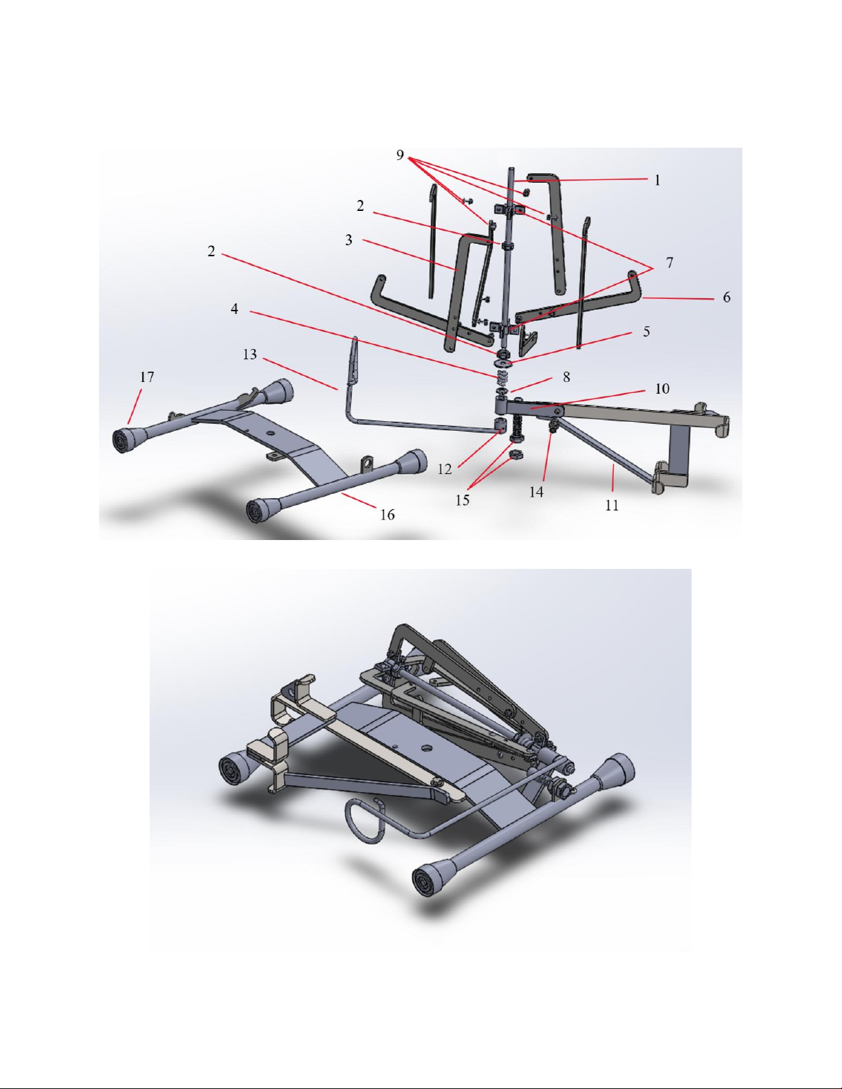
Figure 3
The swivel mount assembly weldment and the spindle rod should slide on the spindle rod underneath the
rest of the arms assembly.
Dismounting the Stud Mount Assembly Weldment from the Floor Bracket
The stud mount assembly weldment will come attached to the floor bracket. In order to
use the floor bracket or the stud mount, they need to be separated. In order to do this, the 5/16”
bolt, washers & nut (FSR-117) need to be removed, which is shown in figure 4. The stud mount

8
assembly can then be detached from the floor bracket. When it is removed, make sure to screw
the 5/16” bolt, washers & nut back onto the stud mount assembly weldment because it will be
used later.
Figure 4
The 5/16” bolt, washers & nut need to be unscrewed and removed first in order to dismount the stud
mount assembly weldment from the floor bracket.
Mounting the Arms Assembly to the Stud Mount Assembly Weldment
Next, the arms assembly can be attached to the stud mount assembly weldment. This is
done by using the 5/16” bolt, washers & nut to fasten the swivel mount assembly weldment to
the stud mount assembly weldment as seen below in figure 5.

9
Figure 5
The 5/16” Bolt is used to attach the stud mount assembly weldment and the swivel mount assembly
weldment together.
Dismounting the Arms assembly from the Out-of-Box Position
Once again, the stud mount assembly weldment will come attached to the floor bracket.
In order to use the floor bracket or the stud mount, they need to be separated. To do this, the
bottom (farthest right in figure 6) 5/8” Jam Nut (HDFR-111) needs to be unscrewed and
removed from the swivel mount assembly weldment (FSR-110) so that the arms assembly slides
off. Do not forget to screw the jam nut back onto the swivel mount assembly weldment since it
will be used later.

10
Figure 6
The arms assembly comes screwed to the floor bracket. This must be dismounted.
Mounting the Arms Assembly to the Floor Bracket
The arms assembly has to be attached to the floor bracket in order to use it as a floor reel.
First screw a 5/8” jam nut (HDFR-111) onto the swivel mount assembly weldment (FSR-110).
Then slide the swivel mount assembly weldment through the hole in the floor bracket as shown
in figure 7. Finally, screw the second 5/8” jam nut underneath the floor bracket to pinch it in
place.
Figure 7
The jam nuts need to be screwed onto the swivel mount assembly, pinching the floor bracket between the
two nuts.

11
To maximize the mobility of the wire guide it is important to align the swivel mount
assembly weldment properly. There is a bump on the floor bracket that was welded there to help
you align the swivel mount. When the 5/8” jam nuts are tightened, make sure that the swivel
mount assembly weldment aligns with the bump on the floor bracket as shown in figure 8.
Figure 8
The swivel mount assembly weldment needs to be aligned with the bump on the floor bracket to
maximize the wire guide rotation mobility.
Mounting to a Stud
Now that everything is assembled, it can be mounted to a 2x4 or 2x6 stud. One side of
the stud mount assembly weldment (FSR-112) has hooks for mounting a 2x6 and the opposite
side is for a 2x4. Either way the procedure is the same. Tilt the stud mound assembly at about a
30° angle as seen in figure 9. Fit the hooks around the stud and rotate the stud mount so that the
crossbar is level.

12
Figure 9
Mounting the assembly is easy. In this case the stud mount is being used for a 2x6 stud, but the two closest can be
used for a 2x4.
The FSR-C Combination Foldable Studreel & Floor Reel is now fully assembled. The
next section will help you if you want to make some adjustments.
Making Adjustments
Raising or Lowering the Wire Tray Arms
To raise or lower the wire tray arms (FSR-102) the user must first unscrew the set screw
in the screw bushing (FSR-101-A) labelled in figure 1 until loose. Then the screw bushing can
slide up or down the spindle rod (FSR-100) to the satisfactory height, and the set-screw can be
tightened again to hold the wire tray arms in the desired position. This process can be seen in
figure 10 below.

13
Figure 10
Screw bushing is slid up the spindle rod to raise the wire tray arms, or slid down to lower the arms.
Adjusting Wire Tray Hub Diameter
Sometimes it is necessary to adjust the diameter of the wire tray hub diameter to
accommodate a different sized spool or wire. To do this, the arms assembly nuts & screws
(FSR-109) that connect the wire try arms (FSR-102) to the wire hub arms (FSR-102) must be
unscrewed and removed. The wire hub arms can then be attached to the wire tray arms using an
alternative mounting hole at the base of the wire tray arms. This process is illustrated in figure
11 below.

14
Figure 11
Wire hub arms can be reattached at an alternate mounting hole in the wire tray arms to accommodate
different spool.
Note: only the two holes in the wire tray arms shown in figure 12 are meant to be used to
mount to the wire hub arms.
Figure 12
Mounting holes in wire tray arm form wire hub arm
Other JK Cables And Connectors manuals
Popular Cables And Connectors manuals by other brands

Philips
Philips SWV2027 Specifications

PCB Piezotronics
PCB Piezotronics 010G25 Installation and operating manual

Anritsu
Anritsu K Connector K102F manual

Crestron
Crestron TPSBLOCK-10 installation guide

Sony
Sony PS VITA PCH-ZUC1 instruction manual

EarthPeople Technology
EarthPeople Technology EPT 232R-US-R1 user manual