JL Audio CleanSweep CL_SSI User manual

Thank you for purchasing a JL Audio CleanSweep®
Signal-Summing Interface for your automotive sound system.
This product has been designed and manufactured to exacting standards
in order to ensure years of musical enjoyment in your vehicle.
For maximum performance and extended warranty
coverage, we highly recommend that you have your CL-SSI installed by
an authorized JL Audio dealer. Your authorized dealer has the training,
expertise and installation equipment to ensure optimum performance
from this product without compromising your vehicle’s functionality.
Due to the complexity of modern vehicle systems we do not recommend
self-installation unless you have extensive experience in
automotive electrical systems.
If you have any questions regarding the instructions in this
manual or any aspect of the product’s operation, please contact your
authorized JL Audio dealer for assistance. If you need further assistance,
please call the JL Audio Technical Support Department
at (954) 443-1100 during business hours.
OWNER’S MANUAL
CleanSweep®CL-SSI
signal-summing interface

2 JL AUDIO CleanSweep®CL-SSI JL AUDIO CleanSweep®CL-SSI 3
PRODUCT OVERVIEW
The CleanSweep® CL-SSI is a dedicated signal
summing interface designed specifically for use
with the JL Audio CleanSweep® CL441dsp OEM
interface processor. Use of the CL-SSI with other
equipment is not supported by JL Audio.
This product performs the following functions:
1) The CL-SSI sums 2-way or 3-way stereo OEM
signals to full-range and outputs the summed
signals to a CL441dsp for response correction.
2) The CL-SSI is designed to accept virtually any
analog audio signal, from low-voltage line-level to
high-power, amplified speaker-level, via its three
input sections. Input Range Switching allows any
combination of line-level and speaker level signals
to be used as inputs. When switched to speaker
level input mode, the CL-SSI’s audio inputs are
compatible with OEM head units and amplifiers
that employ load-sensing startup logic.
3) “Level Trim” potentiometers on the top of
the CL-SSI allow for quick and accurate level-
matching of signals. Each input features a green
LED optimum level indicator flanked by LED’s
indicating “Too Low” or “Too High.” In most
cases, no additional equipment is necessary for
level matching the inputs.
4) Differential-Balanced Input architecture ensures
noise immunity and compatiblity with most
analog output OEM source units or amplifiers.
5) The CL-SSI can be set up in signal-sensing
mode, powering up and providing a 12-volt
turn-on signal for the CL441dsp whenever
signal is detected at its inputs. It can also be
activated by a conventional 12-volt trigger, in the
rare event that the OEM system provides one.
INSTALLATION APPLICATIONS
This product is designed for operation in
vehicles with 12V, negative-ground electrical
systems. Use of this product in vehicles with
positive ground and/or voltages other than 12V
may result in damage to the product and will void
the warranty.
This product is not certified or approved
for use in aircraft.
PLANNING YOUR INSTALLATION
It is important that you take the time to
read this manual and that you plan out your
installation carefully.
The CL-SSI should be mounted as close to the
CL441dsp as possible. The harness supplied for
connecting the CL-SSI’s outputs to the inputs of
the CL441dsp is 3 feet (91 cm) long.
Safety Considerations:
Your CleanSweep® CL-SSI needs to be installed
in a dry environment and in a manner which does
not interfere with your vehicle’s safety equipment
(air bags, seat belt systems, ABS brake systems,
etc.). You should also take the time to securely
mount the CleanSweep® CL-SSI that it does not
come loose in the event of a collision or sudden
acceleration / deceleration.
Stupid Mistakes to Avoid:
• Check before drilling any holes in your vehicle to
make sure that you will not be drilling through a
gas tank, brake line, wiring harness or other vital
vehicle system.
• Do not run system wiring outside or underneath
the vehicle. This is an extremely dangerous
practice that can result in severe damage to your
vehicle and person.
• Protect all system wires from sharp metal
edges and wear by carefully routing them,
tying them down and using grommets and
loom where appropriate.
• Do not mount this product in the engine
compartment, under the vehicle, on the
roof or in any other area that will expose it
to the elements.
PROTECT YOUR HEARING!
We value you as a long-term customer. For
that reason, we urge you to practice restraint in
the operation of this product so as not to damage
your hearing and that of others in your vehicle.
Studies have shown that continuous exposure to
high sound pressure levels can lead to permanent
(irreparable) hearing loss. Automotive audio
systems are capable of producing such high sound
pressure levels. Please limit your continuous
exposure to high volume levels.
While driving, operate your audio system in a
manner that still allows you to hear necessary noises
to operate your vehicle safely (horns, sirens, etc.).
SERIAL NUMBER
In the event that your CleanSweep® CL-SSI
requires service or is ever stolen, you will need
to have a record of the product’s serial number.
Please take the time to enter that number in the
space provided below. The serial number can be
found on the bottom panel of the unit and on the
packaging.
Serial Number:

4 JL AUDIO CleanSweep®CL-SSI JL AUDIO CleanSweep®CL-SSI 5
SIGNAL SENSE MODES
The CL-SSI is designed to act as a turn-on and
turn-off controller for the CL441dsp, which will
control the turn-on of the rest of the aftermarket
equipment in the system. There are two modes of
turn-on operation which can be selected via the
“SIGNAL SENSE” slide-switch located next to the
CL-SSI’s power connector.
Note: The “SIGNAL SENSE” switch of the
CL441dsp must be set to “Off” when used
with a CL-SSI.
Signal Sense: ON
With its “SIGNAL SENSE” switch in the “On”
position, the CL-SSI will only wake up and turn
on the CL441dsp when it senses +12V at its “IGN”
terminal and also senses an input signal from the
OEM audio source. This mode requires that the
“IGN” terminal of the CL-SSI be connected to
a vehicle wire with accessory/ignition-switched
+12V. (See diagram on page 5.)
If the vehicle is turned on with the OEM source
unit turned off, the CL-SSI will remain in Standby
Mode until the OEM source is turned on and
playing. The CL-SSI will go into Standby Mode
(off) approximately one minute after it senses a
loss of input signal or as soon as the ignition is
turned off (whichever comes first).
Signal Sense: OFF
With its “SIGNAL SENSE” switch in the “Off”
position, the CL-SSI will wake up and provide
+12V at its “REM.OUT” terminal whenever it
senses +12V at its “IGN” terminal (regardless
of whether the OEM source is on or not). This
position can be useful if another device is being
used to toggle the CL-SSI on/off, or if the OEM
system has a conventional +12 V turn-on output
(very rare). The “Off” position can also be used
with a manual switch on the wire feeding the
“IGN” terminal for those who desire manual
control of on/off functions. This switch should
be connected to an ignition-switched +12V to
prevent accidental battery drainage.
POWER AND TURNON CONNECTIONS
Before installing the CL-SSI, disconnect the
negative (ground) wire from the vehicle’s battery.
This will prevent accidental damage to the system,
the vehicle and your body during installation.
The CL-SSI has a 4-pin inline jack located next
to the “SIGNAL SENSE” switch on the signal
output end of the processor (see diagram on page
5). This jack accepts the following connections
through the included color-coded wiring harness
and plug assembly:
“+12 V”: Constant +12V
“GND”: Chassis Ground
“IGN”: Switched +12V
“REM.OUT”: Amplifier turn-on (+12V)
Since the CL-SSI does not draw very much
current during operation, 18 AWG - 16 AWG wire
is ample for making all of these connections. Use
good-quality crimp connectors (or solder and
heatshrink tubing) to join the harness leads to any
extended wires. Any wires run through metal
barriers (such as firewalls), must be protected with
a high quality rubber grommet to prevent damage
to the insulation of the wire. Failure to do so may
result in a dangerous short circuit.
Ideally, the “+12V” (constant) and “GND”
(chassis ground) connections should be run to
the same distribution points that the amplifiers
and CL441dsp use for their power and ground
connections. This minimizes the possibility of
noise in the system.
The “REM.OUT” (Remote Output) connection
provides turn-on voltage to the CL441dsp, which
in turn will provide turn-on voltage to the rest of
the aftermarket audio equipment in the system.
The CL-SSI will only turn on when +12V is
present at its “IGN” connection. Conversely, the
CL-SSI will immediately shut off as soon as +12V
is removed from this connection. If the OEM
system does not provide a +12V turn-on lead
(most do not), we recommend that you connect
this wire to a 12-volt circuit in the car that is only
energized with the key in the “Accessory” (ACC)
or “Ignition” (IGN) positions. This will ensure
that the audio system will only operate with the
key in ACC or IGN positions. If the OEM system
provides a +12V turn-on lead (rare) you can
connect this turn-on lead to the “IGN” connection.
CL441dsp POWER
CONNECTION HARNESS
ON OPPOSITE PANEL
SIGNAL SENSE: “OFF”
CL-SSI POWER
CONNECTION HARNESS
CL441dsp
CL-SSI
SIGNAL SENSE: “ON”
SIGNAL
SENSE
Off / On
REM. OUT
IGN
GND
+12V
POWER
CONNECTOR
Left Right Left Right
FRONT OUTPUTS REAR OUTPUTS
IGN
GND
+12V
OUTPUTS
POWER
CONNECTOR
LFRFLRRR SIGNAL SENSE
Off / On
MODE
2-way / 3-way REM. OUT
POWER AND TURNON CONNECTION DIAGRAM
The CL441dsp’s “SIGNAL SENSE” switch must
be set to “OFF” when used with the CL-SSI. The
CL-SSI will act as the CL441dsp’s signal-sensing
turn-on control. The CL441dsp will provide the
turn-on voltage to the rest of the system, ensuring
that the equipment will turn on and off in the
appropriate order, eliminating pops and thumps.
FUSE REQUIREMENTS
The +12V constant wire on the CL-SSI power
harness has an inline 1 amp, fast blow AGC (small
glass-bodied) fuse for protection of the unit. Do
not remove this fuse or replace it with a different
value of fuse.

6 JL AUDIO CleanSweep®CL-SSI JL AUDIO CleanSweep®CL-SSI 7
OEM INPUT CONNECTIONS
The CL-SSI accepts up to six channels (three
stereo pairs) of band-limited input from an OEM
audio source via the three 4-pin plugs located
on the input panel of the main processor (see
diagram on page 9). Three color-coded input
harnesses are included for connection to each of
these plugs.
The input architecture of the CL-SSI is set up
in a differential-balanced configuration, making
its inputs compatible with virtually any analog
audio signal.
Depending on the specific architecture of
your OEM system, you will need to choose
appropriate connection points that maintain OEM
functionality and provide appropriate input to the
CL-SSI. It is recommended that you obtain a service
manual for the vehicle you are working on in order
to locate and identify the correct OEM wires.
Please refer to the following pages for
detailed information on the summing capabilities
of the CL-SSI.
It is very easy to damage expensive vehicle
systems in modern automobiles. Never assume
that you have found appropriate wires without
consulting a reliable wiring diagram or
without performing signal testing with safe
test equipment. If you are not comfortable with
reading wire diagrams or testing signals, please
enlist the services of your authorized JL Audio
dealer to perform the installation.
It is vital to observe correct electrical polarity on
each channel when making input connections.
Failure to do so will result in unrecoverable
frequency response problems.
OUTPUT CONNECTIONS
The CL-SSI’s output harness is designed
for direct connection to the “OEM INPUT
CONNECTOR” of the CL441dsp. The harness
provided is 3 ft. (91 cm) long. Should you need a
longer length, you can cut the harness and splice
extended wires to the harness. Runs longer than 6ft.
(182 cm) will benefit from twisted-pairs of wires
for each channel to avoid noise. Whenever possible,
locate the CL-SSI within reach of the CL441dsp with
the included harness.
OUTPUT CONNECTION DIAGRAM
CL-SSI
OUTPUT HARNESS
CL-SSI
CL441dsp
IGN
GND
+12V
OUTPUTS
POWER
CONNECTOR
LFRFLRRR SIGNAL SENSE
Off / On
MODE
2-way / 3-way REM. OUT

8 JL AUDIO CleanSweep®CL-SSI JL AUDIO CleanSweep®CL-SSI 9
3-Way Mode:
In the 3-Way mode, the CL-SSI will sum
an OEM subwoofer or woofer signal (low-
pass filtered) to a mid-bass or midrange signal
(bandpass filtered) and to a high frequency signal
(high-pass filtered), creating a two-channel,
full-range stereo output.
#BOEQBTTNJESBOHF
-PX1BTTXPPGFS )JHI1BTTUXFFUFS
i*/165"w i*/165#w i*/165$w
(Z K(Z(Z K(Z
To use the CL-SSI in this mode:
1) Flip the “MODE” switch to “3-way”.
2) Connect the OEM subwoofer or woofer signals
to “Input C”. If this signal is mono (one channel
only), connect this signal to both the left and the
right channels of “Input C”, in parallel.
3) Connect the bandpass-filtered midrange signals
to “Input B”.
4) Connect the high-pass filtered signals
to “Input A”.
5) Using the “Level Trim” controls, calibrate
the Input Levels according to the Calibration
Procedure described on page 10.
6) Once properly calibrated, the CL-SSI will
output a single pair of full-range stereo signals
to the CL441dsp as shown in the example
below. The CL-SSI will provide the same two-
channel signal at its front and rear outputs,
feeding all four channels of the CL441dsp.
$-44*0VUQVU
'VMM3BOHF
(Z K(Z(Z K(Z
2WAY OR 3WAY SUMMING MODES:
The CL-SSI can be operated in two distinct
modes to address OEM signals that have been
filtered using 2-Way or 3-Way crossovers. These
modes are selected via the “MODE” switch located
next to the “OUTPUTS” connector on one end of
the unit.
2-Way Mode:
In this mode, the CL-SSI will sum an OEM
subwoofer (or woofer) signal to front and rear
signals that have been high-pass filtered, creating
front and rear full-range output channels while
retaining the functionality of the OEM front-to-
rear fader control.
-PX1BTTXPPGFS )JHI1BTTNJEUXFFUFS
(Z K(Z(Z
i*/165#wSFBS03i*/165$wGSPOU
K(Z
i*/165"w
To use the CL-SSI in this mode:
1) Flip the “MODE” switch to “2-way”.
2) Connect the OEM subwoofer or woofer signals
to “Input C”. If this signal is mono (one channel
only), connect this signal to both the left and the
right channels of “Input C”, in parallel.
3) Connect the rear high-pass signals to “Input B”.
4) Connect the front high-pass signals to “Input A”.
5) Using the “Level Trim” controls, calibrate
the Input Levels according to the Calibration
Procedure described on page 10.
6) Once properly calibrated, the CL-SSI will output
front and rear full-range stereo signals to the
CL441dsp as shown in the example below.
'VMM3BOHF
$-44*0VUQVU
(Z K(Z(Z K(Z
OEM INPUT CONNECTION DIAGRAM
CL-SSI
GRAY
WHITE
GRAY
WHITE
GRAY/BLACK
WHITE/BLACK
GRAY/BLACK
WHITE/BLACK
RIGHT CH.
LEFT CH.
RIGHT CH.
LEFT CH.
GRAY
WHITE
GRAY/BLACK
WHITE/BLACK
RIGHT CH.
LEFT CH.
Subwoofer Channel Inputs
(2-Way or 3-Way)
If mono, connect to both
left and right inputs.
Front High Pass Inputs (2-way)
High Pass Inputs (3-way)
Rear High Pass Inputs (2-way)
Bandpass (Mid) Inputs (3-way)
LEVEL
Spkr / Line
LEVEL
Spkr / Line
LEVEL
Spkr / Line
Engineered by JL Audio in the USA / Made in China
INPUT A
2-way: Front HP
3-way: High
INPUT B
2-way: Rear HP
3-way: Mid
INPUT C
2-way: Sub LP
3-way: Low
LR
If mono, parallel Left & Right Inputs

10 JL A UDI O CleanSweep®CL-SSI JL AUDIO CleanSweep®CL-SSI 11
CALIBRATION PROCEDURE
Once you have made all your system
connections, follow these steps precisely:
1) Select the appropriate summing mode on
the CL-SSI and set the three “Input Level”
switches to “Speaker” position.
a) If you are summing a subwoofer signal to front
and rear high-pass signals (2-way , four channel
sum), switch the “MODE” switch to “2-way”.
—OR—
b) If you are summing a subwoofer signal to
mid-range (bandpass) signals and high-pass
signals (3-way, two channel sum), switch the
“MODE” switch to “3-way”.
2) Turn the CL441dsp’s Master Volume Knob all
the way DOWN.
3) Reconnect the vehicle’s battery ground.
4) Turn the OEM head unit on and make sure
it is playing something (radio or CD, doesn’t
matter right now). Set all OEM head unit tone
controls at “0” (flat), and the balance and fader
controls at their center positions. Turn off
any additional factory signal processing
features like “Loudness”, “Stadium”, “Hall”,
“Sheep Barn”, etc.
5) Verify that the CL-SSI has turned on (lights
on, any color) and has turned on the rest
of the aftermarket equipment, including
the CL441dsp.
6) Slightly raise the CL441dsp’s Master Volume
and verify that audio is passing through to
the aftermarket system. Once verified, turn
the CL441dsp’s Master Volume Control back
to minimum.
7) Insert the “CleanSweep® Calibration CD”
(included with the CL441dsp) into the OEM
CD player, play Track 01 and set the OEM
head unit volume control between half and 3/4
of full volume.
LEVEL MATCHING SIGNALS
Proper level matching of the signals being
summed is essential to achieving a successful
calibration of the CL441dsp.
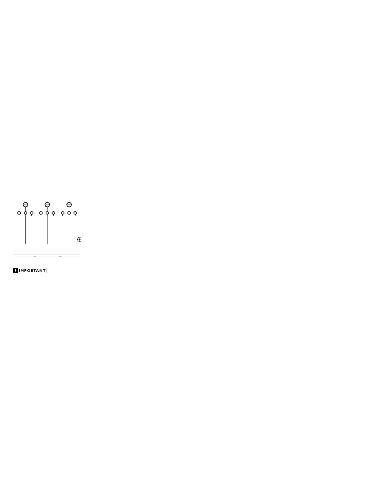
To aid in proper level matching, each of the
CL-SSI’s “Level Trim” sections features a green
LED optimum level indicator flanked by LED’s
indicating level “Too Low” or level “Too High.”
The “Level Trim” potentiometers on the top
of the CL-SSI allow the user to accurately match
the levels of the signals being summed using the
“CleanSweep® Calibration CD” (included with
the CL441dsp). Please read the following section
for details on calibrating the CL-SSI’s “Level
Trim” controls.
Level Trim
To o
Low
To o
High
To o
Low
To o
High
To o
Low
To o
High
Level Trim Level Trim
INPUT A
2-way: Front HP
3-way: High
INPUT B
2-way: Rear HP
3-way: Mid
INPUT C
2-way: Sub LP
3-way: Low
The CL-SSI’s level matching procedure requires
the use of the “CleanSweep® Calibration CD”
included with the CL441dsp. The CL-SSI’s level
indicators have no significance with any other
test-signal or with music program material!
SPECIFICATIONS
CleanSweep® CL-SSI
Signal Summing Interface
Electrical Specifications:
Power Supply Type: PWM Switching Supply - Regulated
Operating Voltage: 9 - 16V DC
Standby Mode Current Draw: < 2 mA
Operating Current Draw: 0.5 A at 13.8V
Recommended Fuse Value: 1 A (Fast Blow)
Recommended Fuse Type: AGC
OEM Input Section:
No. of Input Channels: Three Stereo Pairs
Input Type: Differential-balanced with eight-pin jack
Input Range: 100mVrms - 20Vrms
Input Level Setting: Manual with calibrated LED indicators
Output Section:
No. of Output Channels: Two Stereo Pairs
Output Type: Unbalanced, via multi-pin jack
Maximum Output Voltage: 8 Vrms (per output)
Output Impedance: 470 ohms
Signal to Noise Ratio: <108 dB (with A-Weighted filter at
8.0 Vrms. 20Hz-20kHz)
THD + Noise: < 0.01% at 8.0 Vrms (20Hz - 20 kHz)
Dimensions: LxWxH:
5.02 in. x 4.36 in. x 1.52 in. (128 mm x 111 mm x 39 mm)
PARTS LIST
(1) CL-SSI Signal Summing Interface
(1) Power connection harness
(3) Input connection harnesses
(1) Output connection harness
Due to ongoing product development, all specifications are subject to
change without notice.
8) Using the rotary “Level Trim” controls on the
top of the CL-SSI, level match the signals so that
each LED indicator is steady green. If you have
turned any control to its full clockwise rotation
and have not achieved a green light, flip the
“Input Level” switch for that input to “Line”
and retry. Once you have three green lights, you
have achieved a successful level match.
9) Using a small pointed tool press the
CL441dsp’s “CALIBRATE” button.
10) Wait approximately twenty seconds... lights will
flash in various colors to keep you entertained
and to indicate that calibration is taking
place. After twenty seconds, the lights will
have stabilized and will tell you whether the
calibration has been successful on each channel.
11) If you have four green lights, your
calibration was successful. If you don’t have
steady green lights, refer to the Channel
Status Codes section in the CL441dsp manual
for troubleshooting.
12) If you have steady green lights on the
CL441dsp, you can now proceed to set your
amplifier input sensitivities. Handy test
tones are included for this purpose on the
“CleanSweep® Calibration CD”... then balance
your amplifier channels to taste.
13) Refer to CL441dsp manual for Aux Input level
setting information.
14) That’s it! You’re now ready to enjoy great sound.

JL_CL_SSI_MAN_REV1-07-2006
LIMITED WARRANTY ELECTRONICS USA
JL AUDIO warrants this product to be free of defects in materials and workmanship for a period of
ninety (90) days from the original date of purchase. The warranty term is extended to two (2) years if
installation is performed or approved by an authorized JL AUDIO dealer (proof of installation or approval
required on purchase receipt).
This warranty is not transferrable and applies only to the original purchaser from an authorized
JL AUDIO dealer. Should service be necessary under this warranty for any reason due to manufacturing
defect or malfunction, JL AUDIO will (at its discretion), repair or replace the defective product with new
or remanufactured product at no charge. Damage caused by the following is not covered under warranty:
accident, misuse, abuse, product modification or neglect, failure to follow installation instructions,
unauthorized repair attempts, misrepresentations by the seller. This warranty does not cover incidental
or consequential damages and does not cover the cost of removing or reinstalling the unit(s). Cosmetic
damage due to accident or normal wear and tear is not covered under warranty.
Warranty is void if the product’s serial number has been removed or defaced.
Any applicable implied warranties are limited in duration to the period of the express warranty as
provided herein beginning with the date of the original purchase at retail, and no warranties, whether
express or implied, shall apply to this product thereafter. Some states do not allow limitations on implied
warranties, therefore these exclusions may not apply to you. This warranty gives you specific legal rights,
and you may also have other rights which vary from state to state.
If you need service on your JL AUDIO product:
All warranty returns should be sent to JL AUDIO’s Electronics Service Facility freight-prepaid through
an authorized JL AUDIO dealer and must be accompanied by proof of purchase (a copy of the original
sales receipt). Direct returns from consumers or non-authorized dealers will be refused unless specifically
authorized by JL AUDIO with a valid return authorization number.
Warranty expiration on products returned without proof of purchase will be determined from the
manufacturing date code. Coverage may be invalidated as this date is previous to purchase date. Non-
defective items received will be returned freight-collect. Customer is responsible for shipping charges and
insurance in sending the product to JL AUDIO. Freight damage on returns is not covered under warranty.
For Service Information in the U.S.A. please call:
JL Audio customer service: (954) 443-1100
during normal business hours (9:00 AM - 5:30 PM Eastern Time)
JL Audio, Inc
10369 North Commerce Pkwy.
Miramar, FL 33025
(do not send product for repair to this address)
International Warranties:
Products purchased outside the United States of America are covered only
by that country’s distributor and not by JL Audio, Inc.
Table of contents
Other JL Audio Recording Equipment manuals
Popular Recording Equipment manuals by other brands

Studio Technologies
Studio Technologies 354A user guide

HHB
HHB CDR850 Plus operating instructions

GRASS VALLEY
GRASS VALLEY KARRERA K-FRAME Installation & service manual

IET Labs
IET Labs 1689-9640 User and service manual

Evolution Technologies
Evolution Technologies MK-261 user manual

Laserworld
Laserworld MicroNet Slim manual