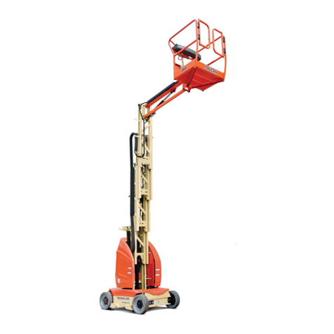
JLG K13 Instruction Manual

ISO 9002
Lic 6080
Operator & Safety
Manual
www.jlg.com.au
K13
Issue: February 2006 PRINTED IN AUSTRALIA 1734722

BEFORE ENTERING PLATFORM,
CHECK ALL OUTRIGGERS
IF YOU ARE IN ANY DOUBT,
CONSULT JLG OR THEIR DEALER.
NEVER USE BASKET
FOR LIFTING
DO NOT OPERATE CLOSE TO
OVERHEAD POWER CABLES
DO NOT SIT, CLIMB OR PLACE
LOADS ON GUARDRAILS
ALWAYS LEVEL MACHINE WITH
OUTRIGGERS BEFORE ELEVATING
DO NOT OPERATE
THE MACHINE UNTIL YOU
HAVE READ THE MANUAL
FOR USE BY
AUTHORISED AND
TRAINED PERSONNEL ONLY

K13
Contents Section
Introduction 1
Description 2
Working Envelope 3
The Operator 4
Warning Notices 5
Pre-Start Checks 6
Road Towing Instructions 7
Power Supply 8
Setting Up 9
Operation 10
Safety Harness 11
Emergency Controls 12
Stowing 13

INTRODUCTION
The JLG K13 is a very versatile means of gaining access in difficult locations.
The machine is extremely safe in operation providing that basic rules are observed in
setting up the machine.
Operators should have read and understood the contents of the manual, and received
full training in the safe use of the machine before attempting to use it.
1.1
I
N
T
R
O
D
U
C
T
I
O
N

DESCRIPTION
The JLG K13 is of the parallel linkage vertical boom design, mounted on a road
towable trailer. The unique yet very simple boom configuration gives the maximum
safety and controllability combined with a robust construction to withstand a heavy
working environment.
The K13 machine is designed for two-man capacity (200 kg S.W.L.)
The machine incorporates a bottom boom with tie rod, a short vertical boom and a top
boom with tie rod. The K13 also has an independent hydraulically operated flick-out
boom for extra manoeuvrability.
The hydraulic system is of a failsafe design throughout, with built in hydraulic lock
valves on all the rams as a precaution against hose failure. The machine is controlled
by means of proportional manual control valves of the direct hand lever operation
type.
Emergency lower valves are fitted as standard to allow the machines to be lowered
from either the platform or the base. There is also a base control valve fitted as
standard, repeating all the functions of the basket control valve.
The outriggers are fitted with interlocks, to prevent the booms being raised without
the outriggers being extended. A simple system of warning lights show the power is
on and each of the outriggers is under load.
The K13 meets or exceeds the applicable requirements of AS1418.10 as originally
manufactured for the intended applications and use.
2.1
D
E
S
C
R
I
P
T
I
O
N

WORKING ENVELOPE
3.1
W
O
R
K
I
N
G
E
N
V
E
L
O
P
E

THE OPERATOR
1.
To operate the machine you must be medically fit and have no problems with
your eyesight or hearing.
2.
You must have a good head for heights.
3.
Your first concern must be the SAFE OPERATION of the work platform, the
safety of the people working with you and/or other persons in your working
area.
4.
You must be familiar with the operation instructions within this manual, and at
no time attempt to operate the machine beyond the recommended limits.
5.
The proper care of the work platform is a major factor in ensuring the safety of
those who work with it. You must not misuse the machine or ignore or
interfere with the devices and equipment which have been provided to
maintain safety.
6.
Operation of the machine should be restricted to personnel who have been
authorised to operate the equipment and have received proper training.
4.1
T
H
E
O
P
E
R
A
T
O
R

WARNING NOTICES
1.
DO NOT operate the machine unless you have been fully trained in the safe
use of the machine.
2.
DO NOT operate the machine on soft, slippery or sloping ground unless
adequate precautions have been taken.
The stabilisers are designed to operate on firm and level ground with a
minimum bearing strength of 31 N/cm
.The maximum load imposed by an
outrigger is 10.3 kN.
Advice should be obtained from JLG as to the type of supports and
precautions required before attempting to operate the machine outside these
parameters.
3.
DO NOT operate the machine unless all four stabilisers are down in full
contact with the ground, the machine is level and the wheels are lifted clear of
the ground.
4.
DO NOT use any equipment in the basket to increase the reach or working
height of the machine, e.g. ladders.
5.
DO NOT fit any additional equipment to the machine which would increase
the wind loadings, e.g. notice boards.
6.
DO NOT use the machine for any application which may produce special
loads or forces; JLG should be consulted for approval giving full details of the
application prior to use.
7.
DO NOT use the machine close to live electrical conductors. This machine is
not insulated and does not provide protection from contact or proximity to
electrical current.
If you are working in an area with overhead power lines, contact your local
authorities to find out the minimum safe approach distances applicable to your
job site. A site-specific risk assessment must be carried out and risk control
measures put in place before work commences. A dedicated observer may be
required along with other risk control measures. Consult AS2550.1 and your
local authorities for details.
8.
DO NOT tow the machine unless all booms and stabilisers are fully locked in
position.
5.1
W
A
R
N
I
N
G
N
O
T
I
C
E
S

WARNING NOTICES
BEAUFORT WIND SPEED SCALE
The Beaufort Scale of wind force is accepted internationally and is used in
communicating weather conditions. It consists of numbers 0 – 17, each representing a
certain range of wind speeds at 10m (33ft.) above ground in the open.
DESCRIPTION OF WIND
SPECIFICATION FOR USE ON LAND
m/sec
0 CALM Calm – smoke rises vertically. 0-0.5
1 LIGHT AIR Direction of wind shown by smoke drift but
not by wind vanes. 0.6-1.5
2 LIGHT BREEZE Wind felt on face; leaves rustle; ordinary
vanes moved by wind. 1.6-3.0
3 GENTLE BREEZE Leaves and small twigs in constant motion;
wind extends light flag. 3.5-5
4 MODERATE BREEZE
Raises dust and loose paper; small branches
are moved. 6-8
5 FRESH BREEZE Small trees in leaf begin to sway; crested
wavelets form on inland waterways. 9-10
6 STRONG BREEZE Large branches in motion, umbrellas used
with difficulty. 11-13
7 NEAR GALE When trees in motion; inconvenience felt
when walking against wind. 14-17
8 GALE Breaks twigs off trees; generally impedes
progress. 18-21
9 STRONG GALE Slight structural damage occurs (chimney
pots and slates removed). 22-24
Numbers 10-17 are not shown in this table.
Approximate corrections for wind speeds at other heights are:
2m subtract 30%; 3m subtract 20%; 6m subtract 10% 15m add 10%; 30m add 25%.
The maximum wind speed for safe operation of a K13 is 12.5m/sec.
5.2
W
A
R
N
I
N
G
N
O
T
I
C
E
S

PRE-START CHECKS
The following pre-start checks should be carried out before taking the machine to the
place of work.
1.
WHEELS
Check tyres for correct pressure for K13 = 45 p.s.i. (3.1 bar).
2.
HYDRAULIC FLUID
The oil level in the tank must be full when booms are in the lowered position.
Use ULTRAMAX HVI 68 (ISO) Grade Oil.
3.
CUT-OUT SWITCHES
All cut-out and safety switches must be working correctly.
4.
EMERGENCY STOP
Check that the emergency stop switches are functioning correctly.
5.
EMERGENCY LOWER
Check that the emergency lower valves are free to operate and are in the fully
closed position.
6.
DAMAGED/LOOSE FITTINGS
Inspect the machine to ensure there are no signs of damaged or loose hoses and
fittings.
7.
PETROL & ENGINE OIL
Check there is sufficient petrol and oil to enable the machine to work a full shift.
6.1
P
R
E
S
T
A
R
T
C
H
E
C
K
S

ROAD TOWING INSTRUCTIONS
Trailer mounted machines fitted with suspension units maybe safely towed behind a
car or van at speeds of up to 80km/hr (50mph) where permitted.
1.
Before towing, check the capacity of the vehicle being used. The machine
weighs 1440 kg. (The weight of machines fitted with certain options may
differ.)
2.
Ensure that the booms are fully lowered and both the boom locking pins are
fitted and holding the booms securely.
3.
Ensure that the jockey wheel has been swung down into the vertical position.
4.
Ensure that the outriggers are fully raised.
5.
Use the jockey wheel to raise or lower the tow bar coupling, to position the
machine above the 50mm ball hitch on the towing vehicle.
6.
Apply the handbrake.
7.
Lower the tow bar coupling down onto the ball hitch using the jockey wheel
and secure the safety chain.
8.
Fully raise the jockey wheel and lock in position.
9.
Release the handbrake.
10.
Plug in the trailer lights (7 pin plug) and check that both vehicle and trailer
lights are working correctly.
7.1
R
O
A
D
T
O
W
I
N
G
I
N
S
T
R
U
C
T
I
O
N
S

POWER SUPPLY
The K13 is powered by a Robin petrol engine. Only use unleaded petrol as fuel.
Before starting the engine, check the oil and petrol levels are correct.
To start the engine from the ground controls, turn the ignition key to the ON position,
ensure the emergency stop button is pulled out, select ground controls, (if engine is
cold hold down the choke button) then press the start button. The choke button, if
used, is to be released as soon as the engine fires.
To start the engine from the platform, turn the ignition key at the ground controls to
the ON position, ensure that emergency stop button at the ground controls is pulled
out, then select platform controls on the controls selector switch. Climb into the
basket. Ensure that the platform emergency stop button is pulled out, (hold down the
choke button if the engine is cold) then press the start button. The choke button, if
used, is to be released as soon as the engine fires.
The choke buttons provided at the controls are only to be used when starting a cold
engine. Always allow the engine to reach its operating temperature before operating
any of the hydraulic functions.
8.1
P
O
W
E
R
S
U
P
P
L
Y

SETTING UP
Do not attempt to set up the machine on steep slopes, ramps or soft ground.
Note: The maximum load that can be exerted by the outrigger foot is 10.3 kN.
HYDRAULIC OUTRIGGERS
1.
Start the engine from the ground controls as per the instructions on the
previous page.
2.
Keeping the black (outrigger enable) button depressed, use the outrigger
control levers to lower each of the 4 outriggers to within 50-100 mm from the
ground.
3.
Still with the black button depressed, use levers 1 and 2 to lower the front
outriggers until the jockey wheel is clear of the ground.
4.
Now use levers 3 and 4 to lower the rear outriggers until the machine is level
(see the “bubble” indicator on the chassis). Check to see that the machine tyres
are off the ground. Make sure that all four of the green outrigger indicator
lights on the control panel are lit up. The boom will not function until all four
of these lights are on. Check that all outriggers are in firm contact with the
ground.
5.
Fold jockey wheel up into horizontal position.
6.
Remove lower and upper boom transport pins and place in dedicated holding
clips.
7.
Before operating the machine, select the platform controls on the controls
selector switch.
9.1
S
E
T
T
I
N
G
U
P

OPERATION
1.
Set the machine up and lower the outriggers as per the instructions on page
9.1. Ensure that the boom transport pins have been removed.
2.
At the ground controls, ensure the key is in the ON position, the emergency
stop button is pulled out and the platform controls have been selected. Climb
into the basket and ensure that the basket emergency stop button is pulled out.
To start the engine, press the start button (holding down the choke button if the
engine is cold). If used, release the choke button as soon as the engine fires.
3.
The platform may now be raised, lowered or slewed in any direction by
operating the control levers in the basket. The decal indicates which lever
operates which function. See Fig 8.
4.
A duplicate set of controls is mounted on the slew turret under the L.H. side
cover which allows the platform to be operated from the ground. Again, the
decal indicates which lever operates which function. See Fig 9.
Figure 8: Basket Controls
10.1
WARNING
Before raising, ensure there are no overhead obstructions or power cables and
the outriggers are properly extended and secured.
O
P
E
R
A
T
I
O
N

OPERATION
Figure 9: Ground Controls
10.2
O
P
E
R
A
T
I
O
N

SAFETY HARNESS
1.
During operation, occupants of the platform must wear a full body safety
harness with a lanyard attached to an authorised lanyard anchorage point. A
permanent anchorage point is provided in the basket for fixing the harness.
11.1
ATTACH SHACKEL HERE
S
A
F
E
T
Y
H
A
R
N
E
S
S

EMERGENCY CONTROLS
1.
EMERGENCY STOP BUTTONS
Red emergency stop buttons are fitted on the machine to stop the motor in an
emergency. These are fitted to both the upper and the lower control boxes. The
emergency stops can be reset by pulling (prior S/No. K133976) or twisting
(S/No. K133976 onwards).
2.
BASKET & BASE EMERGENCY LOWER
In the event of an emergency, the bottom and the top booms may be lowered
by means of emergency lower valves. There is one of these located on each
boom cylinder. In the event of an emergency, an assistant may operate each of
these valves simply by pushing the button on each valve until the
corresponding boom is lowered.
Also, there is a manual pump located on the left-hand side of the platform
control box. This may be used in the event of loss of power to the main pump
or malfunction of the main pump. All basket functions may be operated as per
usual (except the upper and lower booms may only be lowered) while
pumping manually.
3.
EMERGENCY SLEW - In the event of a power failure, the machine may be
manually slewed by holding the slew control valve lever down at the base and
manually indexing the slew platform by means of the 16mm ratchet on the
shaft (red) of the slew gearbox.
NOTE – Before operation of the machine, it is important that both the
operator and some other responsible person on site is aware of the position and
function of the following: -
a. Emergency Stop Buttons.
b. Emergency Lowering Controls.
c. Emergency Slew Drive Shaft.
12.1
E
M
E
R
G
E
N
C
Y
C
O
N
T
R
O
L
S

STOWING
1.
Fully lower all the booms and insert the pegs through the bottom of the
vertical boom and the top boom. Ensure the arms of the pegs are secure in the
retainer.
2.
Lower the jockey wheel to the vertical position.
3.
HYDRAULIC OUTRIGGERS
a. Press the black button on the lower control box.
b. Fully raise the outriggers.
4.
The machine is now stowed for transportation. For road towing instructions
refer to page 7.1.
13.1
S
T
O
W
I
N
G
Table of contents
Other JLG Boom Lift manuals

JLG
JLG EC450AJ Use and care manual

JLG
JLG 1230ES Use and care manual

JLG
JLG 100HX User manual

JLG
JLG 600S Use and care manual

JLG
JLG Skytrak 6036 Use and care manual

JLG
JLG 3394RT User manual

JLG
JLG RT2669 Use and care manual

JLG
JLG 1250AJP Programming manual

JLG
JLG 26MRT Installation and user guide

JLG
JLG RT3394 Use and care manual

JLG
JLG 15MVL Series Use and care manual

JLG
JLG 1932E3 User manual

JLG
JLG Toucan 800 Use and care manual

JLG
JLG E300A Use and care manual

JLG
JLG 400SC Use and care manual

JLG
JLG 600A Installation and user guide

JLG
JLG 800S Use and care manual

JLG
JLG GRADALL 544D-10 Use and care manual

JLG
JLG 0300203771 Instruction Manual

JLG
JLG 100SX Instruction Manual