jobmate HCM550 User manual

Concrete Mixer
Owner’s Manual
SKU NUMBER : 273937
SUPPLIER CODE : HCM550
FOR YOUR SAFETY
READ AND UNDERSTAND THE ENTIRE MANUAL BEFORE OPERATING
MACHINE
Save This Manual for Future Reference

SAFETY
WARNINGS &INSTRUCTIONS
SYMBOL
AFFIXED
TO
THE
MACHINE
UNDERSTAND YOUR MIXER
Read and understand the owner’s manual and labels affixed
to the mixer. Learn its application and limitations as well as
the specific potential hazards peculiar to it.
Become familiar with the controls before operating this mixer.
STAY ALERT
Do not operate the mixer while under the influence of drugs,
alcohol, or any medication that could affect your ability to use
it properly.
Do not use this mixer when you are tired or distracted from
the job at hand. Watch what you are doing at all times. Use
common sense.
AVOID DANGEROUS CONDITIONS
Make sure there is adequate surrounding workspace.
Keep your work area clean and well lighted. Cluttered areas
invite injuries. Keep area around the mixer clear of obstructions,
grease, oil, trash and other debris which could cause persons
fall onto moving parts.
Only use or operate the mixer on solid, flat, level ground that
is capable to support the weight of the mixer and its load to
prevent the mixer from tipping over.
Do not attempt to move the mixer when it is loaded and/or
in operation.
This mixer is intended for the production of concrete, mortar
and plaster. It is not suitable for the mixing of flammable or
explosive substances. Do not use it in areas where fumes
from paint, solvents or flammable liquids pose a potential
hazard.
INSPECT YOUR MIXER
Check your mixer before turning it on. Keep guards in place
and in working order. Do not plug mixer with motor cover off.
Check all bolts, nuts, and screws for tightness before each
use, especially those securing guards and drive mechanisms.
Vibration during mixing may cause these to loosen.
Form a habit of checking to see that all the adjusting tools,
shovels, hand trowels and other tools/equipments are removed
from mixer area before turning it on.
Replace damaged, missing or failed parts before using it.
Warning labels carry important information. Replace any
missing or damaged warning labels.
2

SAFETY WARNINGS & INSTRUCTIONS
SYMBOL AFFIXED TO THE MACHINE
DRESS PROPERLY
Do not wear loose clothing, gloves, neckties or jewelry (rings,
wrist watches). They can be caught in moving parts. Protective
electrically non-conductive gloves and non-skid footwear are
recommended when working. Wear protective hair covering
to contain long hair, preventing it from getting
caught in machinery. Wear a face or dust mask if the
operation is dusty. Always wear safety goggles and/or face
shields. Everyday eyeglasses have only impact resistant
lenses. They are not safety glasses.
DROCESUBATONOD
Never carry mixer by cord or yank it to disconnect it from
socket.
Keep cord from heat, oil and sharp edges.
SDROCNOISNETXE
Extension cords must be no longer than 50 meters in length.
The wire section must be 1.5mm2on 230V to allow
sufficient current flow to the motor. Improper use of
extension cords may cause inefficient operation of the
mixer which can result in overheating and motor damage.
Only extension cords intended for outdoor purpose may
be used. Avoid use of free and inadequately
insulated connections. Connections must be made with
protected material suitable for outdoor use. Make sure that
any extension cord connections are dry and safe. Ensure that
the extension cord is carefully laid out avoiding liquids, sharp
edges and places where vehicles might run over it. Avoid
allowing the extension cord to be trapped underneath the
mixer. Unroll it fully or it will overheat and could catch fire.
KCOHSLACIRTCELEDIOVA
Check that the electric circuit is adequately protected and that
it corresponds with the power, voltage and frequency of the
motor.
Do not plug or unplug the motor while standing in or around
damp or wet ground. Do not use the mixer in wet or damp
areas or expose it to rain.
Prevent body contact with grounded surfaces: pipes, radiators,
ranges, and refrigerator enclosures.
Make sure your fingers do not touch the plug’s metal prongs
when plugging or unplugging the mixer.
KEEP VISITORS AND CHILDREN AWAY
Keep unauthorized persons away from the mixer.
Do not allow children to handle or climb on or in the mixer.
3

SAFETY
WARNINGS &INSTRUCTIONS
SYMBOL
AFFIXED
TO
THE
MACHINE
DO NOT OVERREACH
Keep proper footing and balance at all times when loading
or unloading the mixer.
Never stand on mixer. Serious injury could occur if the mixer
is tipped or if the moving parts are unintentionally contacted.
Do not store anything above or near the mixer where anyone
might stand on the mixer to reach them.
AVOID INJURY FROM UNEXPECTED ACCIDENT
Keep hands out of the way of all moving parts. Do not place
any part of your body or any tool, like shovel in the drum
during operation. When operating, do not pass hands through
the clearance between frame and support arm or the one
between the drum and support arm.
DO NOT FORCE TOOL
It will do a better and safer job at its design rate. Always work
within the rated capacity.
Do not start the motor if the drum is fully loaded. Do not turn
mixer off while full of concrete.
Do not use the mixer for a purpose for which it
was not intended.
The mixer is not to be towed by any vehicle.
NEVER LEAVE MIXER RUNNING UNATTENDED
Do not leave mixer until it has come to a complete stop.
DISCONNECT POWER
Never open the motor cover before unplugging the mixer.
Disconnect from power supply when not in use, before moving,
making adjustments, changing parts, cleaning, or working on
the mixer. Consult technical manual before servicing.
MAINTAIN YOUR MIXER WITH CARE
Clean the mixer immediately after use. Keep the mixer clean
for best and safest performance.
When maintaining this mixer, only the manufacturer’s original
replacement parts may be used.
PROTECT THE ENVIRONMENT
Take left over materials to an authorized collection point or
follow the stipulations in the country where the mixer is used.
Do not discharge into drains, soil or water.
STORE IDLE EQUIPMENT
When not in use, the mixer should be stored in a dry location
to inhibit rust. Keep the mixer away from children and others
not qualified to use it.
4

TABLE OF CONTENTS
Safet
y
Warnings & Instructions ………………...…………………………………………….….......... 2
Electrical Connection ……………………………………………………………………………………...5
Specifications……………………………………………………………………………........................ 5
Contents of Shipping Container ………………………………………………………………….......... 6
A
ssembly Instructions ………………...…………………………………………………………........... 6
Operation Instructions …………………………………………….……………………………............. 9
Maintenance Instructions ………………………………………………………………………............10
Wiring Diagram ………………..…………………………………………………………………...........10
Parts Schematic ……………………………………………………………………………….............. 1
1
ELECTRICAL CONNECTION SPECIFICATIONS
This mixe
r
is double insulated to Class
II .protection and IP44 rated. The
insulation will only remain effective if the
original insulating parts are used
for repairs and the spaces
between the original insulation are
maintained.
Double insulation eliminatestheneed
for the three-wire grounded power cor
d
and grounded power suppl
y
system. Double insulated tools can us
e
either a two or three wire extensio
n
cord.
Model Numbe
r
Moto
r
HCM550
650W S6 30%
Drum Capacity
Drum Mouth
Drum Speed
L
160 Liters
385 mm
30/min
1210 mm
Overall
Sizes
Weight
W
H
840 mm
1290 mm
55.5 kg
Do not connect either core
to the earth pin.
The use of an Residual Current Device
(“RCD”), (earth leakage trip), on 230
V
electrics is recommended. If using a
n
extension cable, plug it directly into th
e
RCD.
When operating in Switzerland,plugthe
mixer only in sockets protected by faul
t
current breaker.
5

CONTENTS OF THE SHIPPING CONTAINER
M8
70
M6
25
M8
70
M8
20
M8
65
2
1
2
1
1
2
2
1
A
B
C
D
ASSEMBLY INSTRUCTIONS
Two people assist in assembly
recommended.
THE
STAND
42 1
M10 20
M10
20
M8
16
M8
20
M8
2
2
10
2
4
E
F
G
H
2
A
1. Slide the wheels over the stub axles. Secure
with hairpin retainers.
6

THE
BOTTOM DRUM
1
M8 20 2
M8 65 1
42 1
D
M8
70
M6
25
2
1
1
B
1. Slide the bearing block on the shaft. Hold i
t
in place with 42 spiral ring.
2. Carefully, and with two people, set the botto
m
drum with suppo
r
ta
r
m onto the side support
s
2. With the frame lying on its side, attach the
support leg as shown. Insert two M8X70 he
x
bolts through the holes from one side, the
n
flat washers, lock washers and nuts from th
e
other side. Slide the spring on the lowe
r
plunger rod. Connect the plunger rods wit
h
a M6X25 hex bott and nut. Hold the sprin
g
in place by inserting a split pin. Bend eac
h
side of the pin outward. Tighten down.
of the stand as shown, so that the bearing
block slots into the channel provided by th
e
side support while the larger diameter shaf
t
sits on the bottom bracket.
3. Line up the holes in the side suppor
t
with those in the bearing block and insert
a
M8X65 hex bolt from one side, then a fla
t
washer, lock washer and nut from the othe
r
side.
4. Place the upper bracket on the larger diamete
r
shaft with the holes lining up with the one
s
in the bottom bracket. Insert two M8X20 bolt
s
through the holes, then the flat washers, loc
k
washers and nuts from below.
THE
MIXING BLADES
M8 70 2
C
3. Turn the frame over and attach the
axle bracket with wheels in the same manner.
4. Make sure all bolts and nuts are tightened. M10 20 2
E
7

Mount the mixing blades inside the bottom drum
loosely as shown - Two holes are provided a
t
the base of the drum into which a M10X20 cros
s
headed screw may be inserted from the outside
.
A
leather washer, flat washer, lock washer an
d
a nut should be threaded on loosely on th
e
inside. The leather washer should be place
d
under the blade down against the drum.
2. Screw a M8X16 hex bolt with lock and flat
washers into each threaded hole i
n
the rim/ring gear. Make sure th
e
tightening process is carried ou
t
progressively.
3. Secure the mixing blades to the upper dru
m
by inserting the two M10X20 cross heade
d
screws, from the outside through the hole
s
NOTE: Two arrows are labeled on uppe
r
drum and bottom drum to mak
e
their position relation. If you hav
e
any difficulty i
n
correctly positioning the mixin
g
blades, it is helpful if yo
u
temporarily mount the uppe
r
drum on the top of the botto
m
drum, rotating it so that the tw
o
4. A leathe
r
washe
r
should be positioned inside
between the drum and blade. Secure th
e
mixing blade on the inside using a flat washer
,
spring washer and nut.
5. Finally, ensure top and bottom mixing blad
e
mountings are tight.
THE
UPPER
DRUM
THE
TIPPING WHEEL
M10
20
M8
16
2
10
F
M8 20 2
G
1. Position the uppe
r
drum on bottom drum
over the rim, making sure the mounting holes
align in both as well as the labeled arrows.
Install the tipping wheel with locking plate on
the frame flange with two M8X20 hex bolts each
with flat washer, lock washer and nut.
8

THE TRANSMISSION CAS
E
Loading
/
Mixing Position
For Morta
r
For Concrete
Emptying Position Storage Position
M8
4
H
Lining up the keyways, slide the transmission
case over the pinion shaft. Secure the case to
the frame with four M8 nuts.
OPERA
TION
INSTRUCTIONS
DRUM TILTING
The tipping wheel provides an easy positive
control of the drum which can be locked in the
mix, discharge and stored position.
The drum is locked in the position by a self-
locating plunger which engages into the tipping
LOADING
Completely unwind the extension
cord. Connect it to the concrete
mixer first before plugging in power
supply.
Always start the mixer before loadin
g
the drum. Loading the drum with
drum rotating.
Do not throw material into the mixe
r
to avoid sticking firmly to the bac
k
ofthe drum. Trickle it steadily ove
r
the ram.
wheel. To tilt the drum, the locking plunger must
be dis-engaged by pressing down the foot pedal
.
This then allows the tipping wheel and drum to b
e
turned in the same direction.
To retain the drum in position, aligning the slot
NOTE:
A
built-in thermal protecter is
arranged in the motor to prevent i
t
from overheating. The therma
l
protecter restores automaticall
y
when the motor cools down.
with the plunger, release the foot pedal and
rotate the tipping wheel until the self-locating
lockin
g
p
lun
g
er en
g
a
g
es into the ti
pp
in
g
wheel. For best results, proceed as follows:
1. Add the required amount of gravel into the
drum
.
9

2. Add the required amount of cement into th
e
drum.
3. Add the required amount of sand into th
e
drum.
4. Pour the required amount of water into th
e
drum.
EMPTYING
Do not turn mixer off while ful
l
of load. Emptying the drum wit
h
drum rotating.
CLEANING
Never put hands inside the dru
m
with drum rotating.
Thoroughly clean the mixer at the end o
f
each day’s operation. Keep your mixe
r
clean. The slightest trace of material left i
n
the drum will harden and attract more eac
h
time you use it until the machine i
s
useless. Dried cement should be scrape
d
out of the drum. Do not throw bricks into mixe
r
drum to clean it out. Do not beat on th
e
drum with a shovel, a hammer or other tool
s
to break up accumulations of dried cemen
t
mix, as damage to the mixer may result. Th
e
drum may be scoured for approximate
2
minutes, using 1” gravel and wate
r
mixture. Then discharge the gravel/wate
r
mixture and hose down the drum assembl
y
inside and out. The IP44 protection clas
s
construction of the concrete mixer enable
s
you to hose down the drum assembly safely.
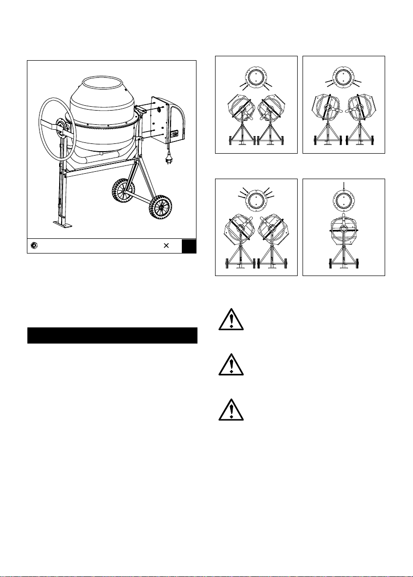
MAINTENANCE INSTRUCTIONS
Ensure the extension cord
is always unplugged before the
motor cover is removed.
The wiring diagram and parts
schematic in this manual are as
reference tools only. Neither the
manufacturer nor distributor
makes any representation or
warranty of any kind to the buyer
that he or she is qualified
to make any repairs to the product
or that he or she is qualified to
replace any parts of the product.
Only qualified technicians
should repair the mixer. Any
maintenance and repairs carried
out, to any of the electric
components must be undertaken by
a qualified electrician.
Parts in a circle should only be fitted
by a qualified electrician.
WIRING DIAGRAM
Do n
o
t po
u
r
o
r spra
y
water directl
y
over the motor cover, especiall
y
the openings in it.
Wipe off an
y
externa
l
materia
l
on
the motor cover. Do not use petrol
,
turpentine, lacquer or paint thinner
,
products. The use of chemical
products or solvents may affect
the properties of the cover which
wa s made of high density
polyethyiene.
10
dry cleaning fluids or similar

PARTS SCHEMATIC
11
Table of contents
Popular Mixer manuals by other brands

Kenwood
Kenwood Chef and Major KM010 series Instructions for repair

KitchenAid
KitchenAid KHM53ER instructions

Sunbeam
Sunbeam mixmaster compact pro mx5950 user guide

PITSOS
PITSOS GMX1264M user manual

Hyundai power products
Hyundai power products HYCM63E instruction manual

Breville
Breville Bakery Boss BEM825 Instruction book