Johansson Colosseum 8500D User manual
Colosseum
8500D
user
manual

2
No part of this manual may be copied, reproduced, transmitted, transcribed or translated into any
language without permission.
Unitron reserves the right to change the specifications of the hardware and software described in
these manuals at any time.
Unitron can not be held liable for any damages resulting from the use of this product.
Specifications are subject to change without notice. 11/11
© Unitron - Frankrijklaan 27 - B-8970 Poperinge - Belgium
T+32 57 33 33 63 F+32 57 33 45 24
email [email protected]
www.johansson.be - www.unitrongroup.com

3
CONTENTS
1 INTRODUCTION
safety instructions ................................................................................................................... 4
package contents .................................................................................................................... 6
2 HARDWARE INSTALLATION ............................................................................................ 6
3 WEBGUI
minimal system requirements................................................................................................ 8
logging into the device............................................................................................................ 8
general configuration............................................................................................................ 10
about.................................................................................................................................... 10
global................................................................................................................................... 11
factory reset....................................................................................................................... 11
firmware upgrade.............................................................................................................. 12
module restart.................................................................................................................... 12
configuration of the input ..................................................................................................... 13
configuration of the output................................................................................................... 16
configuration of the MPEG setting...................................................................................... 20
3 TECHNICAL SPECIFICATIONS ....................................................................................... 21
4 CONDITIONS OF WARRANTY........................................................................................ 22
5 UHF FREQUENCY TABLE.................................................................................................. 23
6 POWER CONVERSION TABLE........................................................................................ 24
4
1 INTRODUCTION
SAFETY INSTRUCTIONS
Read these instructions carefully before connecting the unit
To prevent fire, short circuit or shock hazard:
Do not expose the unit to rain or moisture.
Install the unit in a dry location without infiltration or condensation of water.
Do not expose it to dripping or splashing.
Do not place objects filled with liquids, such as vases, on the apparatus.
If any liquid should accidentally fall into the cabinet, disconnect the power plug.
To avoid any risk of overheating:
Install the unit in a well aery location and keep a minimum distance of 15 cm
around the apparatus for sufficient ventilation.
Do not place any items such as newspapers, table-cloths, curtains,…
on the unit that might cover the ventilation holes.
The unit must not be exposed to any source of heat (sun, heater,...).
Do not place any naked flame sources, such as lighted candles,
on the apparatus.
Do not install the product in a dusty place.
Use the apparatus only in moderate climats (not in tropical climates).
Respect the minimum and maximum temperature specifications.

5
To avoid any risk of electrical shocks:
Connect apparatus only to socket with protective earth connection.
The mains plug shall remain readily operable.
Pull out power plug to make the different connections of cables.
To avoid electrical shock, do not open the housing of adapter.
Maintenance
Only use a dry soft cloth to clean the cabinet.
Do not use solvent.
For repairing and servicing refer to qualified personnel.
Dispose according your local authority’s recycling processes
6
2 HARDWARE INSTALLATION
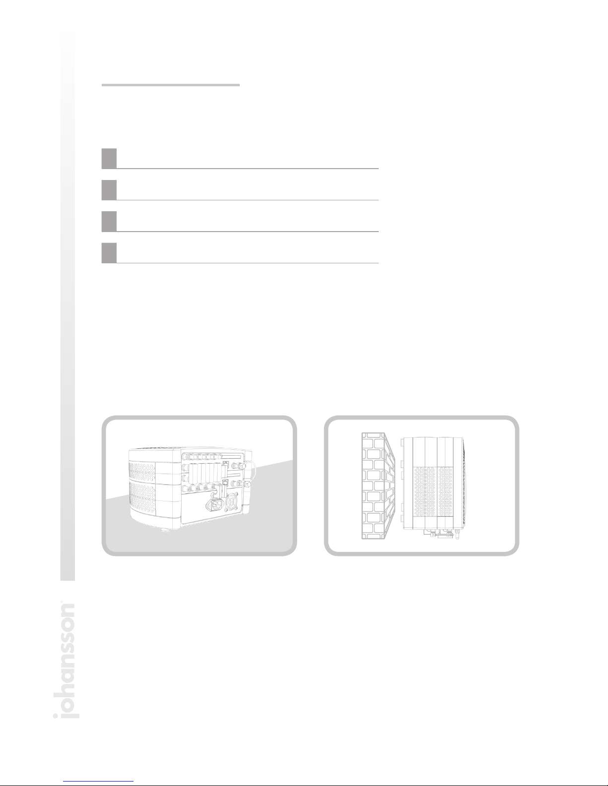
The unit can be placed on a table (1), or mounted to the wall (2).
For wall-mounting, drill two holes, 23 cm apart and insert two screws (min length from
wall to screw head is 12 mm, and diameter of screw head is max 11.5 mm) .
The unit can be mounted with its connectors up or down, but preferrably with the con-
nectors down.
PACKAGE CONTENTS
Be sure all items listed below are included:
1Colosseum (Ref. 8500D)
1CAT6 ethernet cable
1power cord
1user manual
1 2

7
After positioning of the unit (wall or table), connect the cables. The unit is preconfigured
for ASTRA 19.2°. Connect the cables as shown in the picture:
1
5
2 3 4
1ASTRA 19.2° Vertical Low
2ASTRA 19.2° Horizontal Low
3ASTRA 19.2° Vertical High
4ASTRA 19.2° Horizontal High
5Power cord
NOTES
• Connectthe4cablesofaQuad/QuattroLNBtopreventalarmmessages.
Some LNB’s require a lot of power to work properly. The unit is able to
deliver this power, only when the 4 polarities are connected.
• Donotchangethebridgesorloadresistors!

8
3 WEBGUI
MINIMAL SYSTEM REQUIREMENTS
The WebGUI is supported by the following web browsers
(and newer versions of these browsers):
•Chrome4
•Safari3.1
•Firefox3.6
•Explorer8
•Opera10.6
When using a different browser, we cannot guarantee a correct functioning of the
interface. The webGUI will indicate this with a warning message. This message will be
shown every time you browse to another menu item. Please install one of the above
browsers to avoid this.
LOGGING IN TO THE DEVICE
Connect the module to your PC.
The module will obtain an IP address from your PC. For this operation to work,
it is important that the PC is NOT set with a manual IP address!
Set the adapter to obtain an automatic IP address as explained in the following proce-
dure (for Microsoft Windows 7®)
Navigate to the Control Panel (Start Control Panel).
Enter the Network and Sharing Center and go to the Adapter Settings.
9
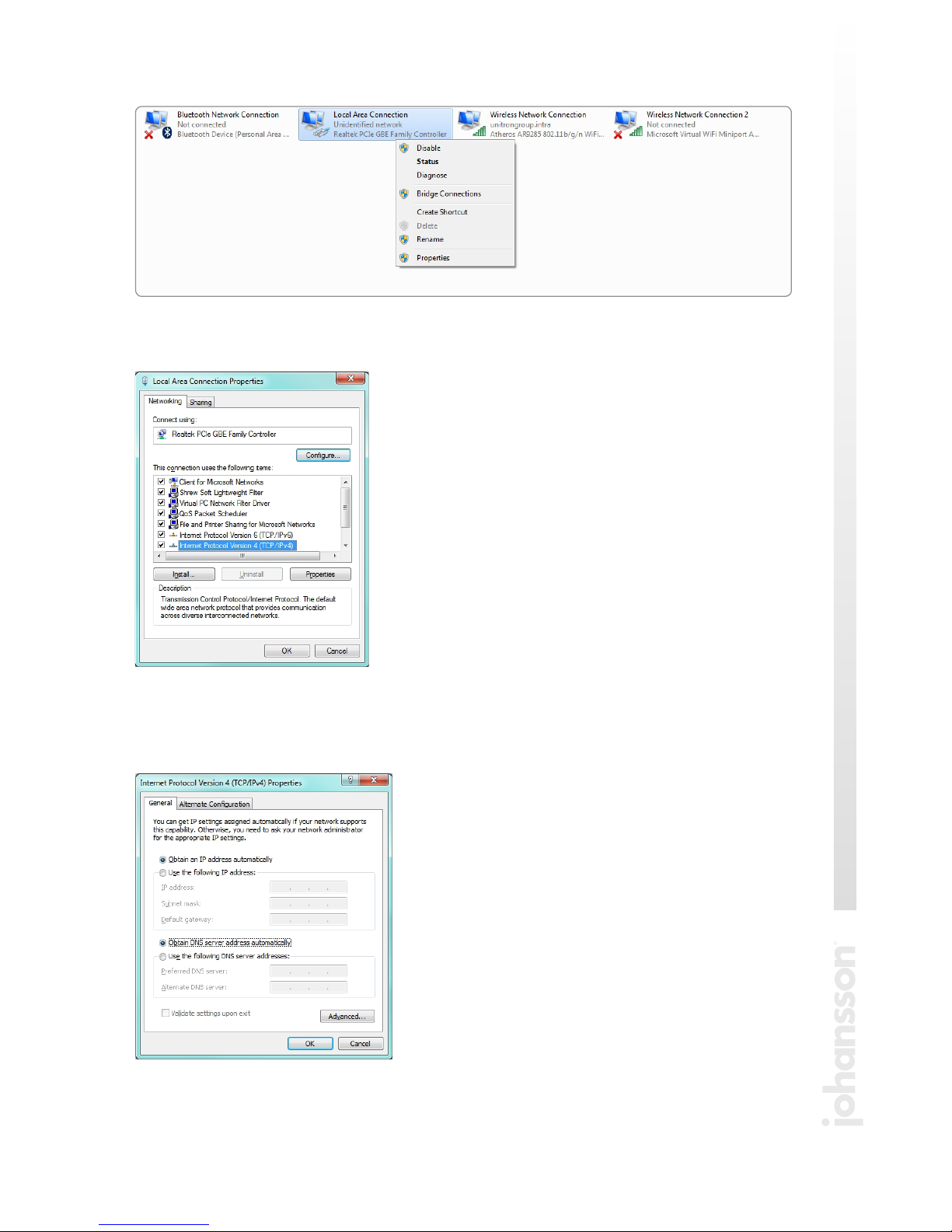
Right-click on the Local Area Connection and choose Properties.
Double click on Internet Protocol Version 4 (TCP/IPv4) to enter the IP settings
of your adapter.
Make sure the ‘Obtain an IP address automatically’ checkbox is selected.
Click OK to save the settings.

10
GENERAL CONFIGURATION
ABOUT
The ‘about’ tab gives some basic information about the device. Here, you can find
the serial number, the software version and release date. These are useful to check
if you have the latest software version installed on your device. New versions can
be found on the website. If you experience serious problems, you can download a
troubleshoot information file. Save this file, and mail it to us for analysis.
Open your network browser, and surf to the name of the module. The name of the first
module is mod1, the name of the second module is mod2. You will now log in to the
module. After logging in, the Summary window appears.
On this screen, you see all the services, streamed by this module. The type of module,
the status and the language are visible on every screen. In the picture above, the status
‘LED’ is green, indicating that there are no alarms. The alarm status is shown when you
move over the status ‘LED’ with your mouse.
status
‘LED’
Table of contents
Other Johansson TV Tuner manuals


