John Bean BFH 1000 User manual

COMPUTER RIDE DIAGNOSTIC
WHEEL BALANCER
OPERATION INSTRUCTIONS
Form ZEEWB519A rev CJuly, 2006
BFH 1000 and BFH 1000 Super
EEWB519A and EEWB519S

Blank page

SAFETY INFORMATION
For your safety, read this manual thoroughly
before operating the BFH 1000 or BFH 1000 Super Wheel Balancers
The JBC BFH 1000 and BFH 1000 Super Ride Diagnostic Wheel Balancers are in-
tended for use by properly trained automotive technicians. The safety messages pre-
sented in this section and throughout the manual are reminders to the operator to exer-
cise extreme caution when servicing tires with these products.
There are many variations in procedures, techniques, tools, and parts for balancing
tires, as well as the skill of the individual doing the work. Because of the vast number of
wheel and tire applications and potential uses of the product, the manufacturer cannot
possibly anticipate or provide advice or safety messages to cover every situation. It is
the automotive technician's responsibility to be knowledgeable of the wheels and tires
being serviced. It is essential to use proper service methods in an appropriate and
acceptable manner that does not endanger your safety, the safety of others in the work
area or the equipment or vehicle being serviced.
It is assumed that, prior to using the BFH 1000 or BFH 1000 Super Ride Diagnostic
Wheel Balancer, the operator has a thorough understanding of the wheels and tires
beingserviced. Inaddition,itisassumedhehasathoroughknowledgeoftheoperation
and safety features of the rack, lift, or floor jack being utilized, and has the proper hand
and power tools necessary to service the vehicle in a safe manner.
Before using the BFH 1000 or BFH 1000 Super Ride Diagnostic Wheel Balancer,
always refer to and follow the safety messages and service procedures provided by the
manufacturers of the equipment being used and the vehicle being serviced.
IMPORTANT !! SAVE THESE INSTRUCTIONS -- DO NOT DISCARD !!
I

IMPORTANT SAFETY INSTRUCTIONS
When using this equipment, basic safety precautions should always be followed, including the
following:
1. Read all instructions.
2. Do not operate equipment with a damaged power cord or if the equipment has been
damaged - until it has been examined by a qualified authorized service technician.
3. If an extension cord is used, a cord with a current rating equal to or more than that
of the machine should be used. Cords rated for less current than the equipment
may overheat. Care should be taken to arrange the cord so that it will not be tripped
over or pulled.
4. Always unplug equipment from electrical outlet when not in use. Never use the
cord to pull the plug from the outlet. Grasp plug and pull to disconnect.
5. To reduce the risk of fire, do not operate equipment in the vicinity of open
containers of flammable liquids (gasoline).
6. Keep hair, loose fitting clothing, fingers and all parts of the body away from moving
parts.
7. Adequate ventilation should be provided when working on operating internal
combustion engines.
8. To reduce the risk of electric shock, do not use on wet surfaces or expose to rain.
9. Do not hammer on or hit any part of the control panel with weight pliers.
10. Do not allow unauthorized personnel to operate the equipment.
11. Do not disable the hood safety interlock system or bypass the intended operation.
12. Use only as described in this manual. Use only manufacturer’s recommended
attachments.
13. Always make sure the power clamp is sucure before spinning the shaft.
14. ALWAYS WEAR SAFETY GLASSES. Everyday eyeglasses only have impact
resistant lenses, they are NOT safety glasses.
15. Balancer is for indoor use only.
16. This equipment uses class II lasers. Do not look into or allow by standers to look into the
laser source.
SAVETHESEINSTRUCTIONS
II

Contents
SAFETY INFORMATION ...................................................................................................................1
1.0 INTRODUCTION .........................................................................................................................1
1.1 SAFETY NOTICE.........................................................................................................................2
1.2 BALANCERAPPLICATION..........................................................................................................2
1.3 BFH 1000 SPECIFICATIONS .....................................................................................................2
1.4 FEATURES ...................................................................................................................................3
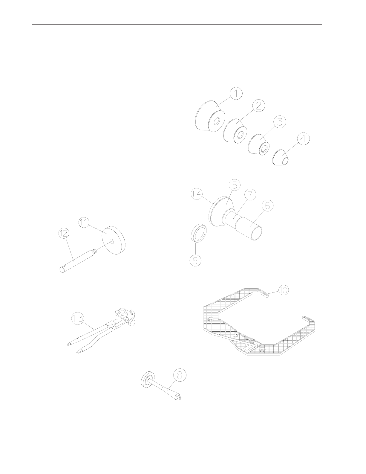
1.5 STANDARD ACCESSORIES .......................................................................................................4
1.6 OPTIONAL ACCESSORIES ........................................................................................................5
1.6 PRE-INSTALLATION CONSIDERATIONS .................................................................................5
1.7 DIMENSIONS OF THE MACHINE ..............................................................................................5
1.8 INSTALLATION AREA REQUIREMENTS ...................................................................................6
1.9 INSTALLATION PRECAUTIONS ................................................................................................6
2.1 ELECTRIC INSTALLATION.........................................................................................................7
2.2 SETUP..........................................................................................................................................7
2.2.2 CUSTOMIZING OPTIMA FEATURES .....................................................................................9
3.0 Physical Layout..........................................................................................................................9
3.1 The Display Screen ....................................................................................................................9
3.2 Menu Keys.................................................................................................................................10
3.2.2 MAIN MENU FUNCTIONS ....................................................................................................11
3.2.3 BALANCING ...........................................................................................................................11
3.2.8 FUNCTION (SETUP) .............................................................................................................13
4.0 Help information .......................................................................................................................14
5.0 POWER CLAMP.........................................................................................................................15
6.0 OPERATION OF THE BALANCER ...........................................................................................16
6.1 CHECK LIST - INSPECTION...................................................................................................16
6.2 BALANCE SCREEN DESCRIPTION .......................................................................................17
6.2.1 WHEEL MOUNTING..............................................................................................................18
6.2.2 STANDARD WHEELS (BACK CONE MOUNT) ...................................................................18
6.2.3 CENTERING LIGHT-TRUCK WHEELS ................................................................................18
6.3 SCAN MODE SELECTION........................................................................................................19
6.4 SPINNING THE WHEEL............................................................................................................20
6.5 SELECTING THE WEIGHT PLACEMENT..............................................................................20
6.6 CORRECTION OF THE IMBALANCE......................................................................................21
6.6 PROCEDURE WHEN SCANNER FAILS TO ACQUIRE A VALID PROFILE ............................21
6.7 VERIFICATION OF THE RESULTS ..........................................................................................21
6.8 VIBRATION PROBLEMS .........................................................................................................22
7.0 SPOKE BALANCING MODE.....................................................................................................22
8.0 BFH 1000 Procedures ............................................................................................................23
8.2 Begin Diagnostic Run .............................................................................................................23
8.2 Profiling the wheel....................................................................................................................23
8.3 BFH 1000 Geometric Matching..............................................................................................25
8.4 Bare Rim Diagnosis .................................................................................................................27
9.0 OptiLine, Balancing a Set of Wheels ....................................................................................28
9.1 OptiLine Customer Calibration ..............................................................................................31
9.0 USER CALIBRATION ................................................................................................................33
10.0 EXPLANATION OF PROGRAM CODES ................................................................................34
11.0 MAINTENANCE........................................................................................................................36
12.0 TROUBLE SHOOTING ...........................................................................................................36


Page1
JohnBean BFH1000 SeriesOperators Manual
1.0 INTRODUCTION
Congratulationsonpurchasing theBFH 1000 Series ComputerRideDiagnostic WheelBalancer.Thiswheel bal-
ancer is designed for ease of operation, accuracy, reliability and speed. With proper maintenance and care your
wheelbalancer willprovidemanyyearsof trouble-freeoperation.
BFH Ride Diagnostics Balancer - Precautions To Observe
YourBFH1000SeriesRide DiagnosticsBalancer utilizesthe latestin electronicsand instrumentationtechnology,
incorporatingthreeseparate scanninglasers alongwith anembeddedcomputer (PC).Following theprecautions
listed below will help to ensure continuous and satisfactory operation of your unit.
1) Install the balancer on a dedicated power line in order to avoid electrical noise and power line fluctuations.
Avoid power cord length greater that 15 feet.
2) The BFH1000 Series Ride Diagnostic Wheel Balancer utilizes red scanning lasers which actually create an
imageof thewheel beingdiagnosed.Installthebalancer awayfrom directsunlight sothatthelaserbeams can
bedetectedby thescanner.Avoidplacing highintensity lampsand infraredheaters nearthe BFHbalancer.
3) Diagnose and balance only those wheels which fit within the specifications of the BFH Balancer:
Rim width = 3 - 20 inches
Rim diameter = 8 - 30 inches
Max tire diameter = 44 inches
Minimum distance required from cabinet to rim edge = 56 mm (2.20 inches) for wheel sizes 13-18 inches in
diameter.
Minimum distance required from cabinet to rim edge = 81 mm (3.19 inches) for wheel sizes 19-24 inches in
diameter.
4) The BFH balancer is designed to properly scan the profile of existing rims. Extreme geometric combinations
of rim diameter and flange offset can inhibit the proper viewing of the rim profile.These exceptional rims can
be properly balanced by manually entering the distance, diameter, and width of the rim.
5) Thewheel guardoftheBFH1000Series RideDiagnosticWheelBalanceralso servesasthe housingfor oneof
the scanning lasers. Since the laser must remain stationary once the spin cycle begins, do not lean on or
otherwise disturb the wheel guard until the spin cycle has been completed.
Instructionson use,operational requirementsand routinemaintenance ofthe machinearecoveredinthismanual.
Thisunit usesan opensourceLinuxoperatingsystemforitsuserinterface.Thisopen sourcecode isavailable
for the cost of shipping and handling to owners of the BFH1000 Series Ride Diagnostic Wheel Balancer.
Requestsmust bemade tothe attentionof balancerproduct managementat theConwayAR addresslisted on
the back of this manual. Please include the owners name, address and unit serial number with all requests.
STORE THIS MANUAL IN A SAFE PLACE FOR FUTURE REFERENCE.
READ THIS MANUAL THOROUGHLY BEFORE USING THE MACHINE.

Page2
1.1 SAFETY NOTICE
This manual is a part of the balancer product.
Read carefully all warnings and instructions of this manual since they provide important information concerning
safety and maintenance.
1.2 BALANCER APPLICATION
The John Bean BFH1000 Series Ride Diagnostic Wheel Balancer is intended to be used as a device to balance,
diagnoseandcorrect car,and lighttruckwheel vibrationproblems withinthe followingrange:
Maximum tire diameter : 44” (1117mm)
Maximumwheeldiameter : 30” (762mm)
Maximum wheel width : 20” (381mm)
Maximum wheel weight : 154 lbs (70 kg)
This device is to be only used in the application for which it is specifically designed.
Any other use shall be considered as improper and thus not reasonable.
Themanufacturershallnotbe consideredliable forpossible damagescausedby improper,wrong ornonreason-
able use.
1.3 BFH 1000 SPECIFICATIONS
Weight ImbalanceAccuracy .05 oz / 1 gram
Weight Placement Resolution ± .7 degrees
Weight Imbalance Resolution:
Roundoff Mode .25 oz / 5 grams
Non-Roundoff Mode .05 oz / 1 gram
Max. Shaft Weight Capacity 154 lbs / 70 kg
Max.Tire Diameter 44" / 1117 mm
Rim Width Capacity 3.0"-20" / 76 mm - 508 mm
Max. Tire Width 21” / 530 mm
RimDiameter Capacity 8"-30"/203mm-762mm
BalancingCycle Time(normal mode) 20 seconds or less
ShaftSpeed atcalculation >200 RPM
Electrical 230vac,1ph, 50-60Hz, 3.2A
RequiredWorkArea 64” x 64” (1626 x1626 mm)
ShippingWeight,complete 645lbs/293kg
ShippingDimensions 72"L X73"WX 63"D(1829x1854x1600mm)
MachineDimensions 64”h64”w64”d(1626x1626x1626mm)
Actual Weight withAccessories 550lbs
OperatingTemperature Range 32-122F/0-50C

Page3
JohnBean BFH1000 SeriesOperators Manual
1.4 FEATURES
•Self test check with every power up cycle.
•Selectable car/light truck limit values
•AdvancedSpokecount capability
•Rim-onlydiagnostics
•Rimcleaningbrake control
•Flat spot detection
•On-boarddiagnosticsfor easyserviceissues
•Selectabledefaultweight placementmode
•AdvancedHelpscreens withillustrations
•Pre-programmedErrorCodes indicateprocedural errorsor safetyconcerns.
•FullyAutomaticAll-Parameter Data Entry.
•FullyAutomatic Rim/Tire Profiling.
•FullyAutomatic Spoke/Split Weight Function for Hidden Weight Placement.
•FullyAutomatic Left and Right Radial & Lateral Runout Measurements.
•BareRimRadial andLateral RunoutMeasurement
•TireTread DepthMeasurement.
•Hands-FreePowerClamping forPrecise WheelPlacement.
•Fast Tire/Wheel Diagnostic System Time, Floor-to-Floor.
•Capturedbackspring eliminateshavingto handlethe backing spring.
•Automaticrecalculationif weightpositionsare changed.Noneed forre-spinningthe wheel.
•Common40mm diametermounting shaft.
•Easy-to-ReadLCDDataDisplay Monitor.
• Dynamic and single weight Static capability.
• Stop-at-Topfeaturessimplifies weightimbalance location
•Automatic WeightType Selection Based on Rim Profile, Indicated by Color Coded Icons
• OptimaBalance featureforreducingweightrequired.
• Built-inspincounter formonitoring balancer productivity.
• Service code access to all Balancer electronic functions for fast, easy diagnosis.
• Operatorselectable round-offmode.
•Wheelpullindex, option(standardon BFH1000Super)
•Wheelrunoutin multiplepositions,optional feature(standardon BFH1000 Super)
•Premium 7 cone set with storage tray option (standard on BFH 1000 Super)

Page4
1.5 STANDARD ACCESSORIES
Standard accessories ( Figure 1) included with the Standard BFH 1000 are:
1 EAM0003J08A Cone, 85-132mm/ 3.3”-5.2”
2 EAM0003J07A Cone, 71-99mm/ 2.8”-3.9”
3 EAM0003J06A Cone, 56-84mm/ 2.2”-3.3”
4 EAM0003J05A Cone, 43-63 mm / 1.7” - 2.5”
5 EAC0058D07A Cup - Large Pressure
6 EAM0005D54A PlasticSleeve
7 EAA0283D53A PowerClamp Nut
8 EAM0005D40A Weight- ShaftCalibration
9 EAC0058D08A Small Presure Disk
10 EAA0247G21A Caliper - Rim Width
11 EAC0060G02A Flange- Cover,Hook
12 EAM0006G01A Pin - Accessory
13 58839 Weight Pliers
14 EAC0058D15A SoftProtective Ring
Figure1

Page5
JohnBean BFH1000 SeriesOperators Manual
Figure3 - Footprint Requirements
1.6 OPTIONALACCESSORIES - SEE FIGURE 2
WheelLift -EAK0221J27A PrinterKit -EAK0221J26A FlangePlate Cart
EAS2081J30A
Stick-on Weight RemovalTool Flange Plates - Kit of 4 7Cone Set-EAK0221J31A
EEHT300A EAK0221J22A (StandardwithBFH Super)
PRE-INSTALLATION CONSIDERATIONS
1.7 DIMENSIONS OF THE MACHINE
Figure2 EAM0003J64 –1.70"T0 2.23"Cone
EAM0003J65–2.03" T03.17" Cone
EAM0003J66–2.38" T03.51" Cone
EAM0003J67–2.74" T03.87" Cone
EAM0003J68–3.08" T04.21" Cone
EAM0003J69–3.42" T05.40" Cone
EAM0003J70–4.21" T06.30" Cone

Page6
1.8 INSTALLATION AREA REQUIREMENTS
Make sure that from the operating position the user can see all of the machine and the surrounding area.
The operator should prevent non authorized persons and/or objects from entering the area which may create
potentialhazards.
The machine should be installed on a stable level floor. Do not install the machine on a uneven floor.
If the balancer is to be installed on a raised floor, the floor must have a capacity of at least 110lbs per sq ft. (5000
N/m² - 500 kg/m²).
It is not required to secure the machine to the floor but is recommended.
Install the machine in a dry, covered area.
The installation of the machine requires a working area of at least 64” x 64” (1626 x1626 mm). See Figure 3
1.9 INSTALLATION PRECAUTIONS
CAUTION! CAREFULLY REMOVE THE BALANCER FROM THE PALLET.
Remove the hardware that secures the machine to the pallet and slide the balancer onto the floor where it is
to be installed.
THE UNIT IS HEAVY AND THE WEIGHT IS NOT EVENLY DISTRIBUTED.
DONOT LIFTTHE BALANCER BYTHE SHAFTORWHEEL GUARDFRAME.
DROPPING THE UNIT MAY CAUSE PERSONAL INJURY OR EQUIPMENT DAMAGE.
2.0 INSTALL ACCESSORY PINS
A. Install the accessory pins (Figures 4a and 4b).Tighten firmly.
B. Install the ConeAccessory tray if installing a BFH 1000 Super Model. See Figure 4b.
C. Place accessories onto the accessory pins or place 7 cone set into tray if installing a BFH 1000 Super.
Figure4a-BFH1000 Figure 4b- BFH1000 Super

Page7
JohnBean BFH1000 SeriesOperators Manual
2.1 ELECTRIC INSTALLATION
ANYELECTRICAL WIRING MUSTBEPERFORMED BYLICENSEDPERSONNEL.
ALLSERVICE MUST BEPERFORMEDBY ANAUTHORIZEDSERVICETECHNICIAN.
Check on the plate of the machine that the electrical specifications of the power source are the same as the
machine. The machine uses 230VAC (+/- 15%), 50-60Hz, 1Ph, 3.2Ampere.
NOTE:
ANY ELECTRICALOUTLET INSTALLATION MUST BE VERIFIED BYALICENSED ELECTRICIAN BEFORE
CONNECTING THE BALANCER.
NOTE:
THIS MACHINE PERFORMS A SELF-TEST ROUTINE ON START-UP. THERE WILL BE A DELAY OF SEV-
ERAL MOMENTS BEFORE UNIT IS READY FOR OPERATION. ANY PROBLEMS DETECTED AT START-
UP WILLRESULT IN THE DISPLAY OFAN ERROR CODE. PROBLEMS DETECTED DURING OPERATION
ARE SAVED TO A LOG FILE WHICH CAN BE RETRIEVED FOR DIAGNOSIS BY ATECHNICIAN.
2.2 SETUP
Every shop has different procedural requirements meaning each machine should be customized to the unique
services performed at that location. Most attributes are set from the Main Function menu. A second “Optima”
menuallows furthercustomization
2.2.1 Customizing the System
A. Select the “Function” key (F1) from the “Welcome” menu. The Main Function setup screen appears as in
Figure5.
B. Press and hold the “F6” button and rotate the wheel to scroll up or down to the desired line item.
C. Press and hold the “F5” button and rotate the wheel to change selected topic to desired value or function.
D. Whenthe desiredfeatureshavebeenselected, saveselections topermanentmemory byselecting lineitem“3”.
Hold the F5 button while rotating the shaft, enter a value of “1”, release to Save to Permanent Memory. See
Figure 5a next page for complete menu listing.
E. Select the “ESC” button on the keyboard to return to the main screen.
Figure5

Page8
Figure 5a - Complete Function Menu listing

Page9
JohnBean BFH1000 SeriesOperators Manual
2.2.2 CUSTOMIZING OPTIMAFEATURES
•From the “Welcome” Screen or Balance Screen, select the “F6” Optima button.
•Select the “F3” Key to enter the menu used to set the limits required for an Optimization procedure.
•Set the values for measurement limits as required by the shop in lines 1-4 and 13-16. See Figure 6
D. Line Item 5 allows the user to select the option of making a profile measurement with each spin or only after
a clamping cycle. Select option “0” (only after clamping) allows a quicker floor to floor time. The unit will then
profile the next wheel assembly after it is clamped. It considers each subsequent spin to be a check spin using
thesame parametersand profile.
E. AdvancedOptionsselectionwillactivate the“Optiline” featureavailable withthe BFH1000Super. See page
28for Operationdetails.
F. Advanced Spoke Detection will enable a multiple pass spoke counter. When enabled the spoke counter will
attempt to detect spoke in mutiple locations.
G. Enable or disable Flat Spot Detection. This feature will detect an abnormally worn area of a tire.
H. Measure Wheel runout in multiple positions if only a wheel is mounted for bent rim diagnosis.
I. Save the values selected by scrolling down to line item 8, (Save to Memory) while rotating the shaft, enter a
valueof“1”,releaseto Save to Permanent Memory
NOTE: It is recommended that default values be used until which time the users feel they can customize
themenus fordesiredresults.
Figure6

Page 9
Figure 7
Figure 8
3.0 Physical Layout.
Refer to Figure 7. - Functional description of the unit:
1. The screen
2. Input panel
3. Gauge arm
4. Stub shaft with power clamp nut
5. Brake pedal
6. Weight compartments
7. Storage areas for cones or clamping devices
8. Tilting frame and hood guard
9. Outer scanner
10. Rear scanner
11. Inner scanner
12.Main Power switch (ON/OFF), rear
3.1 The Display Screen
See Figure 8, Screen with display fields
1-5 Information fields
6Menu fields and Function descriptors.
7Display field of screen
The screen reads out inputs, helpful information,
all measured data and error codes.
Detailed description of display fields
Thescreenis subdividedintovariousdisplay fields,each
ofwhich isassociated witha certaintypeof information.
Information fields
1Number of the installed program version
Machine name
Date and time
2Selected Menu name
3Selected profiling mode
4Electrical compensation
5Error codes
6 Menu fields
Icons illustrating special features or functions are
viewed in the six menu fields. Under every menu
field is the associated menu “F key” which is used
to call the feature illustrated.
7 Display field
Wheel type and rim dimensions
Balancing modes
Amount of unbalance
Direction of orientation and correction position
Optima procedures
Function and Setup Menus
Other Graphical information
1
2
3
4
5
6
7

Page 10
Figure 9
adbc
ef
3.2 Menu Keys
3.2.1 Description of Menu Keys
The assignment of the menu keys F1 to F6 is shown
in the menu fields above the relative keys on the
screen. The menu keys have different functions and
initiate different actions, depending on the program
step.
- Keys without a symbol in the upper right-hand corner
or at the edge initiate an action immediately, such
as F2 on the main screen means to perform a
compensation process. See Figure 9.
- Keys with one or more symbols in the upper right-
hand corner of the menu field or at the edges
initiate various actions:
a - Press key to access a sub-menu, e.g. key F4
Balancing.
b - Press and hold key down while rotating wheel at
same time, e.g. key F11 Number of spokes.
c - Press key to toggle between two options or states,
e.g. key F9 Static / dynamic unbalance.
d - Press key to toggle between several options or
states, e.g. key F21 Weight position for correction
plane.
e - Toggle switch (4 functions): Press edge of key to
carry out the highlighted action, e.g. key F32
Character set: move the cursor in the character set
to the left, to the right, up or down.
f - Toggle switch (2 functions): Press key on top or
bottom to select the highlighted function, e.g. key F8
Precision reading of unbalance and mode select.

Page 11
Icon 5 Icon 6
Icon 7a
Icon 8 Icon 9
Icon 7b
Icon 1 Icon 2
Icon 3 Icon 4
Icon 10
3.2.2 MAIN MENU FUNCTIONS
Icon 1Change to the Function screen
Icon 2Perform adapter compensation run
Icon 3Change to the Balancing screen
Icon 4Change to the OPTIMIZATION MENU
3.2.3 BALANCING
Icon 5Toggle switch, two functions:
Pressed on top:
View and/or edit Data Input (wheel parameters)
Pressed on bottom:
Move the laser position pointer to the desired
location. Button must be held down as the shaft is
rotated. (only when stick-on weights are selected)
Icon 6Toggle switch, two functions; reading only as
long as the key is pressed (quick reading):
Pressed on top:
Precision reading of unbalance, no suppression of
minor unbalance readings.
Pressed on bottom:
Toggles through possible placement locations of
weight placement for conventional balancing run.
Icons 7a and 7b Select static unbalance or Select
dynamicunbalance
Icon 8Number of spokes has been selected and
entered.
Icon 9Number of spokes has not been detected and
must be entered manually if required. Hold the F key
while rotating the shaft until the desired value is
displayed.
Icon 10 Wheel with 6 spokes selected

Page 12
Icon 15 Icon 16
Icon 17
Icon 19 Icon 20
Icon 18
Icon 21 Icon 22
Icon 11 Icon 12
Icon 13 Icon 14
3.2.4 RIM DATA INPUT
Icon 11 Change to the WEIGHT PLACEMENT(mode)
screen.
Icon 12 Change to the RIM TYPE screen
Icon 13 Hold key down and enter the distance rim/
machine by rotating the wheel
Icon 14 Hold key down and enter the rim width by
rotating the wheel
Icon 15 Hold key down and enter rim diameter by
rotating the wheel
Icon 16 Change to the Stored Parameter menu. Must
be in the “Manual” parameter mode
3.2.5
PROFILES SCREEN, STORED PARAMETERS
Icon 17 Select or store a wheel profile. Hold key down
and select copy or store by rotating the wheel.
Icon 18 Store a parameter. Select memory location to
store current wheel profile for later retrieval (yellow
arrow). Select “OK” to enter the values currently in use
to a stored location.
Icon 19 Copy a stored parameter. Select memory
locationfor retrieval(yellow arrow). Select“OK”toenter
the values stored for use in the next balance run.
Icon 20 Accept or enter the selected parameters.
3.2.6 FUNCTION MENU
Icon 21 From the Main Menu, Select FUNCTION to
access screens used to prepare the unit for desired
operation.
Icon 22 Change to the screen USER CALIBRATION,
see Maintenance chapter for user calibration
procedures.

Page 13
Icon 25 Icon 26
Icon 27
Icon 29Icon 28
Icon 23 Icon 24
Figure 10
3.2.7 TEXT EDITOR
Icon 23 Change to the screen TEXT EDITOR
Icon 24 Toggle key, four functions: Move the cursor
within the character set (right, left, up, down) to the
desired character.
Icon 25 Toggle key, four functions: Move the cursor
within the text field (right, left, up, down) to the desired
text box location
Icon 26 Transfer characters from the character set to
the text field
Icon 27 Save text
3.2.8 FUNCTION (SETUP)
Icon 28 Change selected topic to desired value or
function.
Icon 29 Holdbutton androtate thewheel toscroll upor
down to the desired line item.
Setup screen illustration. When desired features have
beenselected, saveto permanentmemory byselecting
lineitem “3”,SavetoPermanentmemory,enter avalue
of“1” withtheF5 buttonwhilerotatingtheshaft.Release
button to save. Select the “ESC” button to return to the
main screen. See Figure 10.
This manual suits for next models
1
Table of contents
Popular Automobile Accessories manuals by other brands

Bosch
Bosch Power DC plus 25kW installation manual

newmotion
newmotion Business Lite View installation instructions

AC Schnitzer
AC Schnitzer LHD Fitting instructions

PNEUMATIC
PNEUMATIC KU-SK-RP00-02 installation instructions

STO N SHO
STO N SHO SNS 32 Installation procedures

Starkey
Starkey 3506 instructions