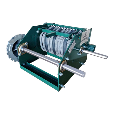
JOHN BLUE CS-150 Series User manual

12-M-71 1 Rev. 11/2021
WARNING: USE OF THIS PRODUCT FOR ANY PURPOSES OTHER THAN ITS ORIGINAL INTENT, ABUSE OF THE PRODUCT, AND/OR MODIFICATION TO THE ORIGINAL
PRODUCT IS STRICTLY PROHIBITED BY JOHN BLUE COMPANY. JOHN BLUE COMPANY RESERVES THE RIGHT TO DENY WARRANTY OR LIABILITY CLAIMS IN ANY/ALL
SITUATIONS INVOLVING MISUSE, ABUSE OR MODIFICATION.
THE ORIGINAL INTENT OF THIS PRODUCT DOES NOT INCLUDE USE WHERE THE MAXIMUM ALLOWED PRESSURE OR TEMPERATURE IS EXCEEDED, AND IT
DOES NOT INCLUDE APPLICATIONS UTILIZING FLUIDS THAT ARE NOT COMPATIBLE WITH THE PRODUCT’S COMPONENT MATERIALS. DO NOT USE THIS PRODUCT WITH
FLAMMABLE OR COMBUSTIBLE FLUIDS SUCH AS GASOLINE, KEROSENE, DIESEL, ETC... FAILURE TO FOLLOW THIS NOTICE MAY RESULT IN SERIOUS INJURY AND/OR
PROPERTY DAMAGE AND WILL VOID THE PRODUCT WARRANTY. IF IN DOUBT ABOUT YOUR APPLICATION, CONTACT YOUR STOCKING DEALER OR THE JOHN BLUE
TECHNICAL STAFF AT 1-800-253-2583.
WARNING: This product can expose you to certain chemicals, which are known to the State of California to cause cancer or birth defects or other reproductive harm. For more information
go to: www.P65Warnings.ca.gov.
SAFETY PRECAUTIONS: EQUIPMENT SHOULD BE OPERATED BY RESPONSIBLE PEOPLE. A CAREFUL OPERATOR IS THE BEST INSURANCE AGAINST AN ACCIDENT.
FILL SYSTEM WITH WATER FIRST AND CHECK FOR LEAKS – REPLACE HOSES WHEN WORN OR CRACKED.
The CS-150 Centrifugal spray pump is available in four configurations, details of each configuration are
outlined on the proceeding pages, the four configurations are:
1.) Shaft Drive (P/N: CS-150)
2.) Hydraulic Drive (P/N: CS-150-HY)
3.) Hydraulic Drive with Manifold (P/N: CS-150-HYM)
4.) Gas Engine Drive (P/N: CS-150RG)
Pump Specifications and Performance:
Max flow: 125 gpm @ 3800 RPM
Max pressure: 90 psi @ 4200 RPM
Shaft Size 3/4” Inner Diameter
Pump Inlet Port Size: 1-1/2” FPT & 220 Flange Inlet
Pump Outlet Port Size: 1-1/4” FPT & 200 Flange Outlet
Installation and
Operation Manual
CS‐150Series
Cast Iron Wet-Seal 1-1/2” x 1-1/4”
Centrifugal Spray Pump

© 2021 John Blue Co.2
1.) Shaft Drive Configuration (P/N: CS-150):
Installation:
This configuration is designed to drive the pump via a pulley system mounted on the pump drive shaft.
For hydraulic motor fitment, you must order a “-HY” or “-HYM” pump for use.
** Note that any plumbing must be supported so that its weight does not hang off the pump, this will void the
warranty.
Storage:
After use, flush the pump with a solution that will neutralize the fluid you have been pumping, and then drain, then
fill the pump with RV antifreeze for storage.
Maintenance:
Inspect the seal reservoir fluid level using the sight window, the fluid level should be above the middle of the
window. If the fluid is dirty, drain the pump by vacuum or turning upside down, then replace with 50/50 premixed
ethylene glycol antifreeze. If fluid is cloudy, impeller side seal may be leaking.

© 2021 John Blue Co.3
CS-150 Pump Components:
Item Description Part # Qty
1 SHAFT 116383-01 1
2 TEFLON SEAL RING 116246-01 2
3 IMPELLER 116379-01 1
4 5/16”-18 X 7/8” LG. HEX HEAD BOLT, PLATED 91013 8
5 5/16” SPLIT LW, PLATED 93023 8
6 1/8” NPT PLUG, PLATED C-431-B 3
7 HOUSING 116380-01 1
8 BEARING HOUSING 116282-01 1
9 PEDESTAL 116381-01 1
10 BEARING 116385-01 2
11 DOUBLE SEAL – CERAMIC 116386-01 1
12 HOUSING RETAINING RING 116387-01 1
13 SHAFT RETAINING RING 116388-01 2
14 HOUSING O-RING – VITON #166 116389-01 1
15 1/8” NPT PLUG, PLATED A-29 4
16 3/8”-24NF FLEXLOC NUT, SS S-3557 1
17 SIGHT WINDOW 116384-01 1
18 ADAPTER O-RING – BUNA #152 116390-01 1

© 2021 John Blue Co.4
2.) Hydraulic Drive Configuration (P/N: CS-150-HY):
Installation:
This configuration is designed to drive the pump via a hydraulic motor.
** Note that any plumbing must be supported so that its weight does not hang off the pump, this will void the
warranty.
Storage:
After use, flush the pump with a solution that will neutralize the fluid you have been pumping, and then drain, then
fill the pump with RV antifreeze for storage.
Maintenance:
Inspect the seal reservoir fluid level using the sight window, the fluid level should be above the middle of the
window. If the fluid is dirty, drain the pump by vacuum or turning upside down, then replace with 50/50 premixed
ethylene glycol antifreeze. If fluid is cloudy, impeller side seal may be leaking.
Hydraulic Drive Specifications:
Max Hydraulic Flow : 4 GPM*
Max Hydraulic Pressure : 3000 PSI*
Pump Port (P) Size : SAE-6
Tank Port (T) Size : SAE-8
Gauge/Load Sense Port (M1G/LS) : SAE-4
Hydraulic line sizes should be sized appropriately to the flow capacity of the tractor / supply and rated for
3000 PSI continuous operating pressure, for flowrates from 0-4 GPM size -6 (3/8”) hose is recommended.
* MAXIMUM WATER FLOW FROM THE PUMP IS ACHIEVED AT 4 GPM HYDRAULIC FLOW, HYDRAULIC
FLOW IN EXCESS OF 4 GPM OR HYDRAULIC PRESSURE IN EXCESS OF 3000 PSI CAN RESULT IN
DAMAGE TO THE HYDRAULIC MOTOR.

© 2021 John Blue Co.5
CS-150-HY Pump Components:
Item Description Part # Qty
1 SHAFT 116392-01 1
2 TEFLON SEAL RING 116246-01 2
3 IMPELLER 116379-01 1
4 5/16”-18 X 7/8” LG. HEX HEAD BOLT, PLATED 91013 8
5 5/16” SPLIT LW, PLATED 93023 8
6 1/8” NPT PLUG, PLATED C-431-B 3
7 HOUSING 116380-01 1
8 BEARING HOUSING 116282-01 1
9 PEDESTAL 116381-01 1
10 BEARING 116385-01 2
11 DOUBLE SEAL – CERAMIC 116386-01 1
12 HOUSING RETAINING RING 116387-01 1
13 SHAFT RETAINING RING 116388-01 2
14 HOUSING O-RING – VITON #166 116389-01 1
15 1/8” NPT PLUG, PLATED A-29 4
16 3/8”-24NF FLEXLOC NUT, SS S-3557 1
17 SIGHT WINDOW 116384-01 1
18 ADAPTER O-RING – BUNA #152 116390-01 1
19 HYDRAULIC MOTOR 116486-01 1
20 3/8” WASHER 93024 2
21 3/8”-16 1-1/4 HEX BOLT, PLATED 90653 2
22 3/8”-16 HEX NUT, PLATED 92024 2

© 2021 John Blue Co.6
3.) Hydraulic Drive with Manifold Configuration (P/N: CS-150-HYM):
Installation:
This configuration is designed to drive the pump via a hydraulic
motor with a manifold.
** Note that any plumbing must be supported so that its weight
does not hang off the pump, this will void the warranty.
Storage:
After use, flush the pump with a solution that will neutralize the
fluid you have been pumping, and then drain, then fill the pump
with RV antifreeze for storage.
Maintenance:
Inspect the seal reservoir fluid level using the sight window, the
fluid level should be above the middle of the window. If the fluid
is dirty, drain the pump by vacuum or turning upside down, then
replace with 50/50 premixed ethylene glycol antifreeze. If fluid is
cloudy, impeller side seal may be leaking.
Hydraulic Drive Specifications:
Max Hydraulic Flow : 25 GPM*
Ideal Hydraulic Flow : 4 GPM
Max Hydraulic Pressure : 3000 PSI*
Pump Port (P) Size : SAE-10
Tank Port (T) Size : SAE-10
Gauge/Load Sense Port (M1G/LS) : SAE-4
Hydraulic line sizes should be sized appropriately to the flow capacity of the tractor / supply and rated for
3000 PSI continuous operating pressure, for flowrates from 0-4 GPM size -6 (3/8”) hose is recommended,
for flowrates from 8-15 GPM size -8 (1/2”) hose is recommended, for flowrates from 15-25 GPM size -10
(5/8”) hose is recommended, and for the M1G/LS Line size -4 (1/4”) hose is recommended.
* MAXIMUM WATER FLOW FROM THE PUMP IS ACHIEVED AT 4 GPM HYDRAULIC FLOW, HYDRAULIC
FLOW IN EXCESS OF 25 GPM OR HYDRAULIC PRESSURE IN EXCESS OF 3000 PSI CAN RESULT IN
DAMAGE TO THE HYDRAULIC MOTOR OR MANIFOLD. ALL HYDRAULIC FLOW IN EXCESS OF 4 GPM
IS BYPASSED BACK TO THE TANK AND CAN CAUSE HEAT GENERATION WITHIN THE HYDRAULIC
SYSTEM.

© 2021 John Blue Co.7
Hydraulic System Operation for CS-150-HYM:
Depending on the tractor’s hydraulic system, please select the appropriate instructions from the below choices. If
you have any questions, please contact John Blue or your John Blue distributor.
If Tractor’s Hydraulic System is Load Sense / Closed Center:
1. Connect M1G port of Hydraulic Manifold to Load Sense (LS) port of tractor’s hydraulic system
2. Shutoff sprayer system valves
3. Set hydraulic flow from tractor/supply to 0-4 GPM per Chart HYM 1.1 (below) to approximate
sprayer flow desired. Do not exceed 25 GPM hydraulic flow
4. Open sprayer system valve to desired sprayer pressure and flow
If Tractor’s Hydraulic System is Pressure Compensated:
1. Shutoff sprayer system valve
2. Set Hydraulic flow from tractor/supply to 0-4 GPM per Chart HYM 1.1 (below) to approximate
sprayer flow desired. Do not exceed 25 GPM hydraulic flow.
3. Open sprayer system valve to desired sprayer pressure and flow
If Tractor’s Hydraulic System is Open Center:
1. Set hydraulic flow from tractor/supply to 0-4 GPM per the below “Chart HYM 1.1” to
approximate sprayer flow desired. Do not exceed 25 GPM hydraulic flow.
2. Open sprayer system valve to desired sprayer pressure and flow

© 2021 John Blue Co.8
CS-150-HYM Pump Components:
Item Description Part # Qty
1 TEFLON SEAL RING 116246-01 2
2 IMPELLER 116379-01 1
3 5/16”-18 X 7/8” LG. HEX HEAD BOLT, PLATED 91013 8
4 5/16” SPLIT LW, PLATED 93023 8
5 1/8” NPT PLUG, PLATED C-431-B 3
6 HOUSING 116380-01 1
7 BEARING HOUSING, HYD 116391-01 1
8 PEDESTAL 116381-01 1
9 BEARING 116385-01 2
10 DOUBLE SEAL – CERAMIC 116386-01 1
11 HOUSING RETAINING RING 116387-01 1
12 SHAFT RETAINING RING 116388-01 2
13 HOUSING O-RING – VITON #166 116389-01 1
14 1/8” NPT PLUG, PLATED A-29 4
15 3/8”-24NF FLEXLOC NUT, SS S-3557 1
16 SIGHT WINDOW 116384-01 1
17 ADAPTER O-RING – BUNA #152 116390-01 1
18 HYDRAULIC MOTOR W/MANIFOLD 116494-01 1
19 3/8” WASHER 93024 2
20 3/8”-16 1-1/4 HEX BOLT, PLATED 90653 2
21 3/8”-16 HEX NUT, PLATED 92024 2
22 SHAFT 116392-01 1
23 SEAL-KIT, VALVE 2 116522-01 1
24 SEAL-KIT, VALVE 3 116523-01 1
25 SEAL-KIT, VALVE 4 116524-01 1
26 KEY # 42704500 (NOT SHOWN) 116525-01 1
23
25
24
14

© 2021 John Blue Co.9
4.) Gas Engine Drive Configuration (P/N: CS-150RG):
Installation:
This configuration is designed to drive the pump via a gas engine. The recommended engine is a Honda GX-160
(John Blue Part Number: 113798-01).
** Note that any plumbing must be supported so that its weight does not hang off the pump, this will void the
warranty.
Storage:
After use, flush the pump with a solution that will neutralize the fluid you have been pumping, and then drain, then
fill the pump with RV antifreeze for storage.
Maintenance:
Inspect the seal reservoir fluid level using the sight window, the fluid level should be above the middle of the
window. If the fluid is dirty, drain the pump by vacuum or turning upside down, then replace with 50/50 premixed
ethylene glycol antifreeze. If fluid is cloudy, impeller side seal may be leaking.

© 2021 John Blue Co.10
CS-150RG Pump Components:

© 2021 John Blue Co.11
Pump Troubleshooting:
Hydraulic System Troubleshooting:
ISSUE PROBABLE CAUSE
Pump makes rattling noise while running Cavitation or pump starvation (suction lift is too high or the inlet line is too restrictive)
Reduced pump output or pressure
Clogged impeller or inlet piping (including strainer)
Leaks in suction line or at inlet gasket
Collapsed suction line
Trapped air in sections of suction line
Suction lift is too great – flooded inlet recommended
Discharge lift is too great
Worn or damaged parts (impeller or volute)
Pump fails to prime or slow prime
Leaks in suction line or at inlet gasket
Suction lift is too great – flooded inlet recommended
Collapsed suction line
Seal reservoir fluid changes level Leak at the input shaft seal if level is low
Leak at the impeller side seal if level is high
ISSUE PROBABLE CAUSE
Reduced sprayer pump water flow or
water pressure
Insufficient hydraulic flow or pressure from tractor
Damaged O-rings on valves in hydraulic motor manifold see “Parts Breakdown”
section above
Insufficient water pressure
No water available. Water pump exceeding water supply
Leaks in water pressure line
External hydraulic leak
Damaged seals or loose components
Assembly bolts loose
No water flow but maximum hydraulic
pressure
Pressure and Tank lines between tractor and HYM are reversed.
Reverse lines on the on hydraulic motor manifold.
Debris in water line stopping water pump from rotating.
Overheated hydraulic system Excessive Hydraulic flow. Max water output available at 4 GPM Hydraulic flow.
Hydraulic flow in excess of 25 GPM not recommended.

© 2021 John Blue Co.12
Note to the Owner
The pump should be inspected annually for any wear or damage to any of the components in order to ensure
proper operation. Enter the date of installation in the space provided for future reference. This information will be
required for ordering replacement parts or servicing your pump.
Our engineering department constantly improves its products. We reserve the right to make design and
specification changes without notice.
DATE OF INSTALLATION: ___________
John Blue Company
Division of Advanced Systems Technology
165 Electronics Blvd., Huntsville AL 35824
Telephone: (256) 721-9090 Fax (256)-721-9091
Toll Free 1-800-253-2583
www.johnblue.com
YOURLOCALDEALER
LIMITED WARRANTY
THIS WARRANTY IS IN LIEU OF ALL OTHER WRITTEN OR EXPRESS WARRANTIES AND REPRESENTATIONS. ANY IMPLIED
WARRANTIES INCLUDING MERCHANTABILITY OR FITNESS FOR ANY PARTICULAR PURPOSE ARE EXPRESSLY LIMITED TO THIS
WRITTEN WARRANTY. JOHN BLUE COMPANY SHALL NOT BE LIABLE FOR CONSEQUENTIAL DAMAGES.
Use of this product for any purpose other than its original intent, abuse of the product, and/or any modification to the original product is
strictly prohibited by the manufacturer, John Blue Company. Any modification to the product should be approved by John Blue Company
prior to use. John Blue Company will deny Warranty claims and liability in any situation involving misuse, abuse or modification.
Each new machine or component manufactured by John Blue Company through original buyer is warranted by John Blue Company to buyer
and to any party or parties to whom buyer may resell, lease or lend the equipment to be free from defects in material and workmanship
under normal use and service. This obligation of John Blue Company under this warranty is limited to the repair or replacement of defective
parts or correction of improper workmanship of any parts of such equipment which shall within one year from the date of John Blue’s original
delivery thereof, be returned to John Blue’s factory, transportation charges prepaid and which John Blue Company shall determine to its
satisfaction upon examination thereof to have been thus defective. When it is impractical to return the defective parts of such equipment to
John Blue’s factory, then John Blue shall have no liability for the labor cost involved in repairing or replacing any such parts and shall be
liable solely for supplying the material necessary to replace or repair the defective parts, provided that prior thereto John Blue Company shall
have determined to its satisfaction that any such parts are thus defective.
This warranty shall not apply to any equipment which shall have been repaired or altered outside John Blue’s factory in any way so as to
affect its durability, nor which has been subjected to misuse, abuse, negligence or accident, or operated in any manner other than in
accordance with operating instructions provided by John Blue Company. This warranty does not extend to repairs made necessary by the
use of inferior or unsuitable parts or accessories, or parts or accessories not recommended by John Blue Company.
John Blue Company makes no warranties in respect to parts, accessories or components not manufactured by John Blue Company, same
ordinarily being warranted separately by their respective manufacturers.
DIVISION OF ADVANCED SYSTEMS TECHNOLOGIES HUNTSVILLE, AL (256) 721-9090
Table of contents
Other JOHN BLUE Water Pump manuals
Popular Water Pump manuals by other brands

Giant
Giant GP7122 operating instructions

ACKERMANN
ACKERMANN 16-2080 user manual

WITA
WITA go.future light 40 series TRANSLATION OF THE ORIGINAL INSTALLATION AND OPERATING INSTRUCTIONS

KMT
KMT STREAMLINE SL-IV PLUS Operation and service manual

Waldbeck
Waldbeck 10031917 manual

Xylem
Xylem e-1532 Series instruction manual