Johnny's Selected Seeds Quick Hoops 7617 User manual

www.johnnyseeds.com 17617.999 | Rev 06/21/2021 | AL, JG, ms
955 Benton Ave., Winslow, ME 04901 •Phone: 1-877-564-6697 •Fax: 1-800-738-6314
Overview:
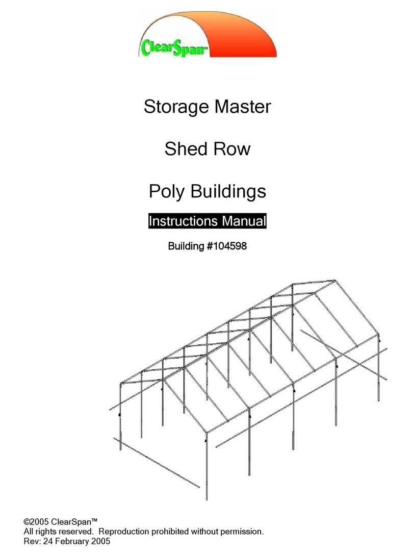
This bender allows you to make spacious 24’ wide tunnels at any desired length using 3 pieces of 1 3/8”
diameter chain-link fence top rail bent into long-radius hoops and connected to form 24’ wide bows, then
placed atop high ground posts created with 1 5/8” diameter 8' chain link line posts. These structures are
designed for use only in areas with little or no snow load, or alternately as three-season structures in any
location by removing the main sheet of greenhouse film before snowfall occurs.
Contents
This bender set includes two separate
jigs. One for the long radius across the
top of the hoops (A), and one for where
the hoops meet the ground posts (B).
This second jig is actually our 3' wide
Quick Hoops Low Tunnel Bender, which
can be used to make 3’ wide by 4.5’ tall
low tunnel hoops out of ½” EMT like the
ones shown to the right.
The set also includes required mounting
hardware for both jigs and a lever bar for
the long radius bender.
September 2016 - Elliptical Tunnel trial
at Johnny's Research Farm, Albion, ME
Instruction Manual for 7617
Quick Hoops™ Elliptical High Tunnel Bender
Copyright © 2021Johnny’s Selected Seeds. All rights reserved.
A
B

www.johnnyseeds.com 2
Materials:
An Excel spreadsheet calculator
has been developed to allow you to
custom design a tunnel to meet
your own operational and financial
needs. It may be downloaded from
the product page for the 7617
Quick Hoops™ Elliptical High
Tunnel Bender or from the
Growers Library on our website.
Simply input the values in the
different option boxes on the upper
left and the spreadsheet will
automatically tell you the following:
•How many of each component
you will need
•Suggest where you can
purchase them
•Give you a square footage
calculation
•Estimated total cost calculation
•Cost per square foot
It will allow you to quickly see cost
estimates for different tunnel
options and allow you to quickly
determine which ones meet your
needs and your budget.
7617.999 | Rev 06/21/2021 | AL, JG, ms

www.johnnyseeds.com 37617.999 | Rev 06/21/2021 | AL, JG, ms
Mounting the Bender Jigs: Both jigs may be mounted to any
solid surface, such as a workbench, a
picnic table, hay wagon, etc. They
may be lag-screwed or thru-bolted
into place. 5/16” mounting holes are
pre-drilled in them and the screws,
bolts, etc. to mount them are also
included. By securing the jigs in fixed
positions, and pulling the tubing
around them, the operator can
maintain precise control of the tubing
being bent.
The long-radius bender jig, wherever
mounted, must have enough room to
accommodate the infeed and outfeed
of pipe, as well as some type of
support at the outfeed end about ¾”
above the mounting surface. This will
prevent "corkscrewing" and ensure
that the hoops and ultimately the
bows are created are in a single
plane and not warped looking. This
can best be accomplished with 3/4”
plywood (shown here) secured with
screws or nails to the surface of the
table.
The short-radius jig does not require
outfeed support, but must be
mounted such that there is sufficient
room for infeed.
Bow Assembly Diagram (3 Hoops are bent and connected to form each Bow):
Hoop #1
Hoop #2
Hoop #3
Short radius
bender
Long radius bender
Hoop being bent
Lever bar

www.johnnyseeds.com 4
Bending the Hoops:
Hoop #1
1. After determining how many bows your high tunnel will have, set aside three times that number of top rail
pipes so they can be bent.
2. Make two marks, one at 7” and one at 12”, from
the swaged (male) end of the first pipe to be bent.
3. Insert the swaged end of a pipe into the holding
strap at the end of the long radius bender. Insert
so that the 12” mark is just to the left of the holding
strap.
4. With a smooth motion, pull back as if on a long oar
(do not push), and bend the pipe all the way around
the bender until the pipe just touches the bender at
the end closest to you. Stop. Do not bend past the
end, or the arc you create will not be smooth.
5. Release tension until the pipe is loose in the holding
strap and move it through the holding strap about
half the length of the bender itself. Twist the pipe
with your hands so that the portion protruding past
the holding strap is flat to the plywood before
bending further. This will prevent corkscrewing of the
pipe. It is best (but not necessary) if another person
stands on that portion of pipe intermittently while
bending.
6. Repeat steps 4 and 5 until about 3’ of unbent pipe
remains beyond the closest end of the bender, or if
bending becomes difficult.
7. Insert the smaller (male) end of the lever bar into the
female end of the pipe. This effectively makes the
pipe longer and will instantly give you more leverage
for bending the rest of the pipe.
8. Continue, repeating steps 4 through 7 until the rest
of the pipe is bent. Remove the lever bar from the
pipe and the pipe from the bender.
9. Drive a wood screw or nail 6” away from the
center bolt of the short radius bender. This
measurement is an approximation and may have to
be altered after the first hoop has been completed.
7”
12”
Lever bar
3.
2.
4. - 6.
7.
9.
Swaged end
7617.999 Rev 06/21/2021 | AL, JG, ms

www.johnnyseeds.com 5
10. Insert the swaged end of the partially bent pipe into
the holding strap at the end of the short radius
bender. Insert so that the 7” mark is just to the left
of the holding strap.
11. Pull back and bend around the short radius bender
until the pipe just touches the wood screw or nail
from step 9. See photos bottom right.
12. Remove the pipe from the bender. This is Hoop #1.
Hoop #2
13. Insert the swaged end of the pipe into the holding strap at the end of the long radius bender. This pipe
does not need to be marked. Insert just past the swage to prevent canting or kinking that portion of the
pipe.
14. Perform steps 4 through 8 for the entire length of the pipe.
15. This is Hoop #2.
Hoop #3
16. Make two marks, one at 7” and one at 12”,
from the non-swaged (female) end of the next
pipe.
17. Insert the non-swaged end of the pipe into the
holding strap at the end of the long radius bender.
Insert so that the 12” mark is just to the left of the
holding strap.
18. Perform steps 4 through 8 for the remaining length
of the pipe.
19. Insert the non-swaged end of the partially bent pipe
into the holding strap at the end of the short radius
bender. Insert so that the 7” mark is just to the left
of the holding strap.
20. Pull back and bend around the short radius bender
until the pipe just touches the wood screw or nail
from step 9.
21. Remove the pipe from the bender.
22. This is Hoop #3.
7”
12”
10.
11., 20.
16.
17.
19.
11., 20.
17.
18.
20.
20.
7617.999 Rev 06/21/2021 | AL, JG, ms
www.johnnyseeds.com 6
Assembling the Bows:
1. In a flat area, lay out Hoop #1, #2, and #3 as shown
in the diagram above.
2. Insert the swaged end of Hoop #2 into the non-
swaged end of Hoop #1.
3. Insert the swaged end of Hoop #3 into the non-
swaged end of Hoop #2.
4. Drive a self-drilling tek screw through both of the
connections created in steps 1 through 3.
5. Flip the hoop over and repeat for the opposite side.
6. Lay out three pieces of pipe at the base of the now
connected hoops and connect them similarly. This
will serve as a straight edge.
1.
2., 3.
4., 5.
6.
4.
4.
2., 3.
7617.999 Rev 06/21/2021 | AL, JG, ms
www.johnnyseeds.com 7
7. Variances in wall
thickness between
different lots of top
rail can cause the
bend radius to
vary. The bottom
portions of the bow
(shorter sections of
Hoop #1 and Hoop
#3) should be at a
right angle to the
straight pipes. If
they are, repeat
steps 1 through 22
of Bending the
Hoops and steps 1
through 5 above
for the remainder
of the hoops. If
not, proceed as
follows:
8. With one person standing on the peak of the assembled bow and one standing with one foot firmly on each
side of one of the short radius bends, use the lever bar to bend the bottom of the bow until it is at a right
angle to the straight edge pipes. Generally, both sides will be either ‘toed in’ or ‘toed out’. Repeat for the
opposite side as necessary.
~ 90o
7.
8.
7617.999 Rev 06/21/2021 | AL, JG, ms
www.johnnyseeds.com 8
9. If the bow ends were ‘toed in’, remove the
wood screw or nail from step 9 of Bending the
Hoops and set it at 7” away from the center
bolt of the short radius bender.
10. If ‘toed out’, remove the wood screw or nail
from step 9 of Bending the Hoops and set it at
5” away from the center bolt of the short
radius bender.
11. Repeat steps 2 through 12 of Bending the
Hoops and 1 though 5 of Assembling the
Bows for the next bow.
12. Lay this bow over the first bow and determine
if moving the screw or nail has corrected the
problem.
13. Adjust the screw or nail and repeat steps 11
and 12 as necessary.
14. Once corrected, repeat steps 1 through 22 of
Bending the Hoops and steps 1 through 5
above to create the rest of the bows.
Creating ground posts from chain
link fence posts
Ground posts are made from 1-5/8” chain link
fence "line post" material, which is commonly
available in 8 ft. lengths. 3 ft. of the post will be
driven in the ground, leaving 5 ft. exposed, for
nice, high sidewalls (see diagram to right).
No prefabrication is necessary for these, unless
desired. We simply drilled through the pipes and
then the boards during frame assembly.
9.- 13.
7617.999 Rev 06/21/2021 | AL, JG, ms
www.johnnyseeds.com 9
Creating Angle Braces:
1. Eight angle braces (four for each end of the tunnel) must be made from four pieces of 1-3/8" top
rail. These pieces should be about 5 ft. long (exact length is not critical). Do this by cutting the
swaged end off the top rail and then cutting it in half.
2. Flatten the ends with a large bench vise or hammer; ensure that the ‘flats’face the same direction.
3. 'Dog ear' cut both corners off each end.
4. Pre-drill each end with a 5/16" drill bit.
5. De-burr any cut ends of the pipe and
pre-drilled holes using a hand file, die
grinder, or bench grinder. It may be
necessary to ream out the holes after
deburring by re-drilling.
1.
1.
2.
3.
4.
5.
5.
7617.999 Rev 06/21/2021 | AL, JG, ms

www.johnnyseeds.com 10
Hints on setting the corner ground posts:
Use the following diagrams to help you set the corner posts in a perfect rectangle.
A
B
A > B
Tunnel is
crooked.
A
B
A = B
Tunnel is
squared off.
3. Measure out from
C2 the desired
tunnel length.
24 ft.
4.Make a mark at that
measurement spot at
what looks to be
square with the
opposite end of the
tunnel.
1. Set the first
corner post C1.
2. Using a tape measure,
set the second corner
post C2.
7. Take measurements A and B above.
8. While maintaining the 24 ft. width,
adjust the two marks to the right
or left until A and B are equal.
9. Set corner posts C3 and C4.
C1
C2
C4
C3
C1
C2
C1
C2
Start here.
5. Measure out from
C1 the desired
tunnel length.
6.Make a mark at that
distance that is also 24
ft. from the mark
made in step 4.
Tunnel forms
a perfect
rectangle.
C1
C2
X
X
X
X
X
X
7617.999 Rev 06/21/2021 | AL, JG, ms
www.johnnyseeds.com 11
Site preparation and setting the ground posts:
Note: Some of the following photos (like the
one at the bottom of this page) will not be of
this exact tunnel, but they will illustrate the
subject matter at hand.
1. Prepare the footprint of the tunnel as you
would with open soil in a field.
2. Weed Barrier - An option to consider at
this point is weed barrier along the edges
of the tunnel. This is traditionally an area
where weed control is difficult and some
fabric that suppresses weeds can be very
effective here. If you choose this option,
proceed to step 4.
3. If you choose to forgo weed
barrier, proceed as follows:
a. Using a ground post driver and
sledge hammer, set the four
corner ground posts first per the
diagram below. It is best to do
this from a stable ladder and
start the posts with someone
else holding them vertical.
JSS #9482
Ground Post Driver
1
2
3
4
3.a.
3.a, b.
JSS #9482
Ground Post Driver
7617.999 Rev 06/21/2021 | AL, JG, ms
www.johnnyseeds.com 12
b. Run a long tape measure from
corner post 2 to corner post 3.
Secure one end to post 2. Pull
it tight and secure the other
end to post 3. Secure with duct
tape, clamps, or something
similar. This will serve as a
gauge as well as a straight line
for setting the other posts.
c. Using the long tape measure
as a guide, set the rest of the
posts for this side of the tunnel
at your desired spacing (most
often 4’apart).
d. Repeat steps b and c for the
other side of the tunnel.
4. If you do choose to use weed barrier,
proceed as follows:
a. Perform step 3.a. on the previous page to set
and square the four corner posts.
b. If you have a pair of D-handle garden forks or
spades, you can quickly set up your weed
barrier on a makeshift spool such as this. This
makes handling and cutting to length very easy.
A piece of top-rail is used as the spindle.
Position at one end of the tunnel location and
offset, so that it faces down the side of what will
eventually be the tunnel. Pull a few inches of
the weed barrier off the roll, and with a utility
knife, cut it down the center so that you have
started two 2’ wide strips.
c. Have one person hold the utility knife near the
roll with the blade through the fabric, while one
or two others pull the fabric off the roll and walk
with it down the side of the plot until you reach
the opposite end.
d. Cut it to length, leaving about 1’ of overlap on
each end. A yellow centerline mark should be
conveniently placed at or near the center of
each of the two 2’ wide strips. Position each 24’
apart on center and parallel.
3.c, d.
4.b.
4.c.
JSS #9724
Pro 5 Weed Barrier
Landscape Fabric
7617.999 Rev 06/21/2021 | AL, JG, ms
www.johnnyseeds.com 13
e. Make a 2" long cut centered between the
sides of the fabric (probably on the yellow
line) that is about 1’ in from one end. Make
just a single cut in line with the length of the
fabric. Slip the corner post near this end of
the fabric through the slit you just made. With
only a single slit, the fabric will be somewhat
snug against the post, which helps prevent
weeds from growing up through the hole.
A tip about woven landscape fabric - Keep the
top of the weed barrier fabric free of soil as
best you can. If soil is allowed to collect on it,
weeds will likely germinate in that soil and root
through the weed barrier, which will make
them difficult to kill and remove by physical
means.
f. Go to the opposite end of the fabric, pull it straight and somewhat taught, and make a
similar cut that is even with the corner ground post at that end. Slip it over the ground
post and smooth out the weed barrier along the length of the tunnel.
g. Secure the edges of the weed barrier to the ground with fabric staples along its edges.
A hammer is sometimes helpful in difficult soils.
h. Repeat steps 4.b through g. for the opposite side of the tunnel.
i. Run a long tape measure down the center of one of the pieces of weed barrier fabric
and secure to the corner posts with clamps, etc.
j. Make 2" slits with a razor knife for the rest of the ground posts on that side of the
tunnel. For example, make a cut every 4’if your tunnel will have 4’bow spacing.
k. Drive ground posts in each of the slits.
l. Repeat 4.i. - k. for the opposite side of the tunnel until all the ground posts are set.
4.g.
4.i., j.
4. k.
JSS #9723
Fabric Staples,
box of 500
7617.999 Rev 06/21/2021 | AL, JG, ms
www.johnnyseeds.com 14
Framing the Tunnel:
1. Bows: Transport the first “end wall” bow to the furthest corner ground posts and insert until the bow ‘seats’
firmly against the top of the ground posts. Repeat for all other bows.
2. Ridge Pole:
a. Raise a piece of top-rail up
pipe over the top of the
tunnel near one of the end
walls, center laterally, and
secure the non-swaged
(female) end of the pipe to
the endwall bow with a
cross-connector. Cross-
connector bolts should be
positioned on the inside of
the tunnel and the end of
the pipe should be flush
with the outside of the
endwall bow. Cover the end
of the pipe with duct tape.
Note: If this end of the
tunnel will have scissor
doors, leave about 6” of
pipe protruding past the end
wall to attach the scissor
doors to later on.
See page 31 for
description and
illustration of
Scissor Doors.
1.
JSS #9542
Cross-
connectors
(sold in pairs)
2.a.
2.a.
2.a.
2.a. - e.
7617.999 Rev 06/21/2021 | AL, JG, ms
www.johnnyseeds.com 15
b. Attach the end of a long tape measure to the end of
the ridge pole with a clamp, etc. and run the tape
measure reel to the opposite end of the tunnel.
Center it laterally and leave it hanging off the
opposite end wall bow so that its own weight is
keeping the tape taught.
c. Adjust the position of the peak of the next bow so
that it is 4’from the previous bow and secure the
ridge pole to that bow with a cross-connector.
d. Slide the non-swaged end of a piece of top-rail over
the swaged end of the ridge pole. Secure together
from beneath with a #10 x 3/4" hex-head self-drilling
tek screw.
e. Using the tape measure as a guide, continue adding
top-rail and securing with cross-connectors as above
for the remaining length of the tunnel. When you
reach the opposite endwall, the top-rail will likely be
protruding past it. If this end will have scissor doors,
leave 6” protruding and cut off the rest. Otherwise cut
the pipe flush to the outside of the end wall and duct
tape over the end.
f. Further secure all cross-connectors installed above
from inside the tunnel with #10 x 3/4" hex-head self-
drilling tek screws by screwing through the side of the
cross-connector and into the bow and also through
the side of the cross-connector and into the ridge
pole. This will prevent any slippage later on.
2.b.
2.c.
2.d.
2.e.
7617.999 Rev 06/21/2021 | AL, JG, ms
www.johnnyseeds.com 16
3. Angle Braces: At this point, these
must be installed so that all bows are
vertical and plumb.
a. In one corner of the tunnel, slip a
1-3/8" brace band over the end
wall bow, two 1-5/8" brace bands
over the second ground post, and
one 1-5/8" brace band over the
third ground post.
b. Position the 1-5/8" brace band on
the third hoop's ground post at
ground level, with its tabs pointing
toward the closest end of the
tunnel, compress them with a pair
of needle nose Vise Grips. Loosely
secure one end of an angle tie to
the brace band with a 5/16"-18 x
1.25" carriage bolt and 5/16" nut.
Remove the Vise Grips.
c. Raise the opposite end of the
angle tie up and rest it against the
next bow. Slide both 1-5/8" brace
bands up the second ground post
until the lower brace band is
aligned to receive the end of the
angle tie. Clamp in place with the
Vise Grips. Loosely secure with a
5/16"-18 x 1.25" carriage bolt and
5/16" nut. Remove the Vise Grips.
d. Position the second brace band on
the second bow so that it is resting
on the previously attached brace
band and pointing toward the
closest end of the tunnel. Clamp
with the Vise Grips and loosely
secure with a 5/16"-18 x 1.25"
carriage bolt and 5/16" nut.
Remove the Vise Grips.
e. Raise the opposite end of the
angle tie up and rest it against the
end wall bow. Slide the 1-3/8"
brace band up the end wall bow
until the brace band is aligned to
receive the end of the angle tie. Clamp in place with the Vise Grips. Loosely secure with a 5/16"-18 x
1.25" carriage bolt and 5/16" nut. Remove the Vise Grips.
f. Using a plumb bob or long level, adjust the end wall bow so that it is plumb (vertically level). All bows
should move together. While holding the end wall in that position, quickly tighten all the nuts on the
angle ties' brace bands.
g. Secure all brace bands installed above from inside the tunnel with #10 x 3/4" hex-head self-drilling tek
screws by screwing through the side of the brace band and into the bow or ground post. This will
prevent any slippage later on.
h. Repeat steps 3.a. through 3.g. for all four corners of the tunnel.
3.b.
3.c.
3.d., g.
3.e.
3.a. - g.
7617.999 Rev 06/21/2021 | AL, JG, ms
www.johnnyseeds.com 17
4. Purlins (optional): These are horizontal pipes of top-rail, similar to the ridge
pole, that are added for strength. They are attached to the bows from
beneath to prevent collection of water and/or snow in the plastic pockets that
would be created if they were attached to the top. You can install two, four, or
none at all, depending on the desired strength. We do not recommend
trellising to them. Install them the same way as the ridge pole, except cut
them flush to the endwall of the tunnel. Do not forget to duct tape the ends and
tech screw the cross-connectors and purlin joints.
Note: If this end of the tunnel will have scissor doors, leave about 6” of pipe
protruding past the end wall on two of the purlins to attach the scissor doors to
later on.
5. Hipboards: We are using 5/4" x 6" x 16'
decking for our hipboards and baseboards.
You can choose to use any material you like.
First, determine what height you would like
your hipboards to be. Ours were about
shoulder height, right at the top of the ground
posts and offered very good ventilation.
a. Measure and cut a 10’length of board to
be used as the first section of hipboard
(this measurement is based on 4’bow
spacing to center board seams between
bows. If you have different spacing, adjust
as necessary). Clamp it to the top of the
groundposts at the end of one side of the
tunnel.
b. With a 5/16" bit, drill through the
groundpost and bow first, then through
the hipboard. Fasten the end of the
hipboard to the end wall bow with a 5/16"-
18 x 3" carriage bolt inserted from the
outside and secured with a flat washer
and 5/16" hex nut. Repeat for the next
bow.
c. Clamp the next board in place at the top
of the groundposts, abbutting the first.
4.
4.
5.b.
5.a.
7617.999 Rev 06/21/2021 | AL, JG, ms

www.johnnyseeds.com 18
d. Pre-cut and place a 2’piece of patch board
inside the seam created by the two
hipboards. Center and clamp in place.
e. With a 5/16" bit, pre-drill four holes as
shown through the patch board and the two
hipboards. Fasten with four 5/16"-18 x 3"
carriage bolts inserted from the outside and
secured with flat washers and 5/16" hex
nuts.
f. Repeat step 5.b. for each of the remaining
bows the boards are attached to.
g. Continue on down the tunnel, repeating steps 5.c. through 5.f. until the last hipboard is in place and a
section of hipboard is protruding outward past the opposite end wall.
h. Cut the hipboard off flush with the outside of the end of the opposite end wall bow.
i. Repeat steps 4.a. through 4.h. for the opposite side of the tunnel.
6. Baseboards: These are installed the same
way as the hipboards except for the
fasteners used to secure them and the need
to align them, since they lay flat against the
ground.
a. Measure and cut a 10’length of board to
be used as the first section of baseboard.
Clamp it to the ground posts on one side
of the tunnel. Similar to the first hipboard,
this 10’length will allow the baseboards
to be joined in between the bows, where
there is room to do so.
b. With a 5/16" drill bit, drill through the
ground post first, then through the
baseboard. Fasten the end of the
baseboard to the end wall ground post
with a 5/16"-18 x 7" J- bolt inserted from
the outside and secured with a flat
washer and two 5/16" hex nuts.
c. Clamp the next section of baseboard to
the tunnel ground posts so that it butts up
to previous one.
5.d., e.
6.a.
6.b.
7617.999 Rev 06/21/2021 | AL, JG, ms
www.johnnyseeds.com 19
d. Pre-cut and place a 2’piece of patch board
inside the seam created by the two
baseboards. Center and clamp in place.
e. With a 5/16" bit, pre-drill four holes as
shown through the patch board and the two
baseboards. Fasten with two 5/16"-18 x 3"
carriage bolts inserted from the outside and
secured with flat washers and 5/16" hex
nuts.
f. Repeat step 5.b. for each of the remaining
ground posts the baseboards are attached
to.
g. Continue down the tunnel, repeating steps
5.c. through 5.f. until the last baseboard is
in place and a section of baseboard is
protruding outward past the opposite end
wall. Before attaching, cut the last
baseboard to length so that it is flush with
the outside of the end of the last ground
post.
h. Repeat steps 5.a. through 5.g. for the
opposite side of the tunnel.
7. Poly Latch Channel on the Hipboards and
Baseboards: Poly Latch Wire and Poly Latch Channel
are used to hold the main covering in place and secure it
along the length and above the roll up sides. Hereafter
we will simply refer to them as “wire” and “wire channel”.
a. Using #10 x 3/4" phillips self-drilling tek screws about
every 12", secure lengths of channel end for end down
the middle or lower side of the outside of the hipboard
for the full length of the tunnel. Cut off any excess on
the opposite end so it is flush to the end of the
hipboard.
b. Prepare a section of wire channel to hold an overlap
panel of plastic that will prevent drafts and heat loss at
the ends of the roll-up sides (shown on page 27) as
follows: Cut to length and secure a 4’ 2” section of wire
channel. Secure it to the end wall bow and the next bow
in with #10 x 3/4" phillips self-drilling tek screws. You
may allternatey secure it to the top of the outside face
of the baseboard if desired.
c. Using clamps, hold cut-to-length pieces of wire
channel in between the hipboard and baseboard on
the outside edge of the first and second groundposts.
Secure with #10 x 3/4" phillips self-drilling tek screws
about every 12”.
6.d., e.
6.g.
7.a.
7.b.
7.c.
7617.999 Rev 06/21/2021 | AL, JG, ms

www.johnnyseeds.com 20
Traditional End Walls:
Note: If you would like to build lower cost “Scissor
Doors” instead, please skip to page 30.
There are a great many ways to go about this, few
of which could be considered wrong. We are
illustrating how we decided to craft a traditional end
wall for our 14' x 200' trial tunnel. There are no
rules. Build your end wall however you like. We do
hope you are able to get some ideas and inspiration
from ours. This is how we did it...
Note: Some of the photos shown here are of our
Quick Hoops Gothic Tunnel.They are only used to
illustrate the methods, which are the same.
1. Poly Latch wire channel: this is used to hold
the end wall plastic on as well as secure the
main covering later on.
a. Start by attaching wire channel to the outside
and top of the end wall bow by using clamps
and forming it around the bow. Start at the
hipboard and work all the way over the ridge
pole.
b. Secure with #10 x 3/4" phillips self-drilling tek
screws about every 12". Adding an extra one
at each end of the channel is a good idea to
prevent failure, since the channel has
preloaded stress and will want to spring back
quite a bit if allowed.
c. Continue all the way over and cut to length just shy of the top of the opposite hipboard.
2. Endwall Baseboard:
a. With a 5/16" bit, pre-drill two holes as
shown through both sides of the endwall
ground posts on both sides of the tunnel as
shown to the right.
b. Precut a 5/4" x 6" x 16' decking board to 12’
long. Place it across the bottom of the end
wall with one end flush to the outside of the
baseboard. Using the pre-drilled holes
made in step 2.a. above, drill through the
board and fasten to the ground post with
5/16"-18 x 3.5" carriage bolts inserted from
the outside and secure with a 5/16" hex nut.
1.a.
1.a. - c.
2.a.
7617.999 Rev 06/21/2021 | AL, JG, ms
Other Johnny's Selected Seeds Greenhouse Kit manuals
Popular Greenhouse Kit manuals by other brands

GrowSpan
GrowSpan 500 Series manual

Blumfeldt
Blumfeldt 10030109 Assembly instructions

GardenSkill
GardenSkill POP-UP POLY CAGE Series instructions

Robinson
Robinson 5' Lean-To Assembly instructions

Palram
Palram Mythos 6'x10' Assembly instructions

WILLAB GARDEN
WILLAB GARDEN Green Room 3181-FDG&XDF Assembly instructions