manuals.online logo
Brands
  1. Home
  2. •
  3. Brands
  4. •
  5. Johnson Controls
  6. •
  7. Industrial Equipment
  8. •
  9. Johnson Controls DMPR-KC204 Manual

Johnson Controls DMPR-KC204 Manual

Installation Bulletin
Issue Date 0998
© 1998 Johnson Controls, Inc. 1
Part No. 44-598-108, Rev. A www.johnsoncontrols.com
Kit Includes
Figure 1: Jackshaft Kit Components
Table 1: Jackshaft Kit Components
Item Description Quantity
-204
Quantity
-205
Quantity
-206
1Mounting Bracket with Bushing 2 2 3
23/4 inch Galvanized Tubing 5 feet 5 feet 10 feet
3Hose Clamp 3/4 inch I.D. 2 2 2
45/16-18 x 1-1/2 inch Bolt 1 2 3
5Crank Arm 1 2 3
6No. 5/16-18 Nut 1 2 3
7Connection Link 1 2 3
8PushNut 246
9ClevisPin 246
10 Screw, 12-24 x 1/2 inch, Self-tapping 6 8 12
11 DriveArm 123
12 Blade Arm 1 2 3
13 U-Bolt w/Nuts 2 4 6
14 Couplers 0 12 24
15 Rivets 0 30 60
16 No. 10-32 x 1-1/4 inch Hex-head Screw 2 4 6
17 No. 10-32 Hex Nut 2 4 6
Note: Cut tubing as required.
Items 11 and 13 are available as kit DMPR-KC203.
Items 14 and 15 are available as kit DMPR-KC202.
Tools Required
•drill, 3/16 inch (5 mm) drill bit and 1-1/4 inch hole saw
•screwdriver, flat-blade, 5/16 inch or No. 12 nut driver
•hammer
•wrench, 5/16 and 7/16 inch
DMPR-KC204, DMPR-KC205, and DMPR-KC206 Jackshafts
2 DMPR-KC204, DMPR-KC205, and DMPR-KC206 Jackshafts Installation Bulletin
Procedures
Table 2: Jackshaft Location
Damper Height, in. Blade
Greater than 11 but less than 24 No. 1 or 3
Greater than 24 but less than 48 No. 3 or 5
Greater than 48 but less than 76 No. 5 or 7
Note: Minimum height required for jackshaft
operation is 11 inches.
1. Locate the labeled preferred driving blade. If the
labeled driving blade is not available, locate the
drive blade from Table 2.
Note: It is preferred to use a drive blade near the
center of the panel height to distribute the
torque evenly.
2. Using a 3/16 inch (or equivalent) bit, drill two holes
for the blade arm (item 12 in Figure 1). For best
results:
Figure 2: Single-Piece Blades
•16-gauge Blades - Drill out the first punch
marks from the end channel.
Figure 3: Double-Piece Blades
•Double-piece Blades - Drill out the second set
of nuggets from the end channel.
Figure 4: Airfoil Blades
•Airfoil Blades - Measure 1-1/8 inches from the
end channel and drill on the lines etched in the
blade.
3. Secure the blade arm to the preferred driving blade:
•Use the two 12-24 x 1/2 inch self-tapping
screws (item 10 in Figure 1) for 16-gauge and
double-piece blades.
•Use the No. 10-32 x 1-1/4 inch hex-head
screws (item 16 in Table 1) and No. 10-32 hex
nuts (item 17 in Table 1) to secure the blade
arm to airfoil blades.
Note: One-panel dampers, go to Step 9.
Figure 5: Coupling Dampers
4. Position the panels side-by-side on the floor with
the blades closed and the labeled sides facing the
same direction.
5. Place the couplers (item 14 in Figure 1) on each
blade pin on one panel as shown in Figure 5.
DMPR-KC204, DMPR-KC205, and DMPR-KC206 Jackshafts Installation Bulletin 3
6. Slide the panel without the couplers towards the
panel with the couplers. The blade pins should line
up with the couplers.
Figure 6: Securing Dampers Together
7. Make sure that the bottom of each damper is
aligned.
8. Use the drive rivets (item 15 in Figure 1) provided
in each hole along the end channels of the two
adjoining dampers to secure the dampers
together.
Note: Repeat Steps 4 through 8 if there are three
panels.
9. Remove the shipping clips securing the blades and
operate by hand to verify operation.
Figure 7: Side View of Mounting Bracket Position
10. Position the mounting bracket (item 1 in Figure 1)
on the framework (see Figure 7) so that the
jackshaft tubing will be aligned with the jackshaft
location selected from Table 2. Punch mark the
location of the mounting holes that will line up with
the end channel mounting holes. Repeat for each
mounting bracket.
11. Drill a 3/16 inch (5 mm) diameter hole for each
punch mark.
Figure 8: One-Panel Connection (DMPR-KC204)
Figure 9: Two-Panel Connection (DMPR-KC205)
Figure 10: Three-Panel Connection (DMPR-KC206)
4 DMPR-KC204, DMPR-KC205, and DMPR-KC206 Jackshafts Installation Bulletin
12. Attach each mounting bracket on the framework
using two 12-24 x 1/2 inch self-tapping screws
(item 10 in Figure 1) per mounting bracket.
13. Slide the jackshaft tubing (item 2 in Figure 1)
through one mounting bracket until it is almost to
the other mounting bracket.
14. Install one hose clamp (item 3 in Figure 1) onto the
tubing and position it against the first mounting
bracket.
Figure 11: Installing Crank Arm
15. Install one crank arm (item 5 in Figure 1) onto the
jackshaft tubing. Do not tighten.
Note: Repeat Steps 13 through 15 if there are three
panels.
16. Install the second hose clamp on the inside edge
of the final mounting bracket, leaving enough room
to allow the tubing to be inserted through the other
mounting bracket.
17. When the tubing is through all mounting brackets,
position the two hose clamps against each
mounting bracket to prevent side-to-side
movement of the tubing. Make sure enough tubing
is available to install the final crank arm.
18. Secure the connection links (item 7 in Figure 1) to
each crank arm and blade arm using the clevis
pins (item 9 in Figure 1) and push nuts (item 8 in
Figure 1).
19. Slide the remaining crank arm onto the tubing and
connect it to the connection bracket using
connection link, clevis pins, and push nuts.
20. Install a 5/16-18 x 1-1/2-inch-long bolt (item 4 in
Figure 1) and No. 5/16-18 nut (item 6 in Figure 1)
to each crank arm. Refer to Figure 11.
Figure 12: Installing Drive Arm
21. Install the drive arm (item 11 in Figure 1) and
secure it with the U-bolts and nuts (item 13 in
Figure 1).
22. Manually rotate the jackshaft to check for proper
operation before attaching the actuators.
For application at conditions beyond these specifications, consult the local Johnson Controls representative. Johnson Controls, Inc. shall not be liable
for damages resulting from misapplication or misuse of its products.
Controls Group www.johnsoncontrols.com
507 E. Michigan Street
P.O. Box 423
Milwaukee, WI 53201 Printed in U.S.A.
This manual suits for next models

2

Other Johnson Controls Industrial Equipment manuals

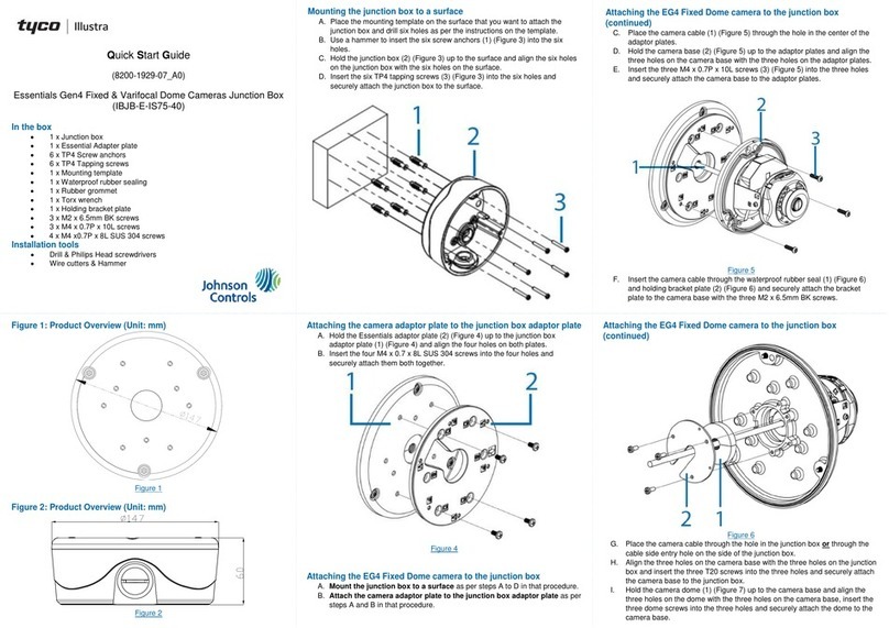
Johnson Controls tyco Illustra IBJB-E-IS75-40 User manual

Johnson Controls

Johnson Controls tyco Illustra IBJB-E-IS75-40 User manual

Johnson Controls ZW Series User manual

Johnson Controls

Johnson Controls ZW Series User manual

Johnson Controls S300 Series Assembly instructions

Johnson Controls

Johnson Controls S300 Series Assembly instructions

Johnson Controls DSV060B User manual

Johnson Controls

Johnson Controls DSV060B User manual

Johnson Controls ANSUL CD05A-1 User manual

Johnson Controls

Johnson Controls ANSUL CD05A-1 User manual

Johnson Controls Frick AcuAir Owner's manual

Johnson Controls

Johnson Controls Frick AcuAir Owner's manual

Johnson Controls Frick Vyper 305/254 Horsepower User manual

Johnson Controls

Johnson Controls Frick Vyper 305/254 Horsepower User manual

Johnson Controls Frick ECH Owner's manual

Johnson Controls

Johnson Controls Frick ECH Owner's manual

Johnson Controls PN-TP10L User manual

Johnson Controls

Johnson Controls PN-TP10L User manual

Johnson Controls YORK YHAU-CGN Installation and operating instructions

Johnson Controls

Johnson Controls YORK YHAU-CGN Installation and operating instructions

Johnson Controls Frick IDC Owner's manual

Johnson Controls

Johnson Controls Frick IDC Owner's manual

Johnson Controls York YK Installation guide

Johnson Controls

Johnson Controls York YK Installation guide

Popular Industrial Equipment manuals by other brands

EZTURNER EZ 29 Operating instructions manual

EZTURNER

EZTURNER EZ 29 Operating instructions manual

S&C VacuFuse II Quick operation guide

S&C

S&C VacuFuse II Quick operation guide

Nexen AIR CHAMP DPC-9T user manual

Nexen

Nexen AIR CHAMP DPC-9T user manual

Diablo Controls DSP-222 Operation manual

Diablo Controls

Diablo Controls DSP-222 Operation manual

RGB Technology 106-01-02 Technical and Operational Documentation

RGB Technology

RGB Technology 106-01-02 Technical and Operational Documentation

Graco 253017 Instructions-parts list

Graco

Graco 253017 Instructions-parts list

Apex Digital EK76 manual

Apex Digital

Apex Digital EK76 manual

Mitsubishi Electric PAC-SH51SP-E installation manual

Mitsubishi Electric

Mitsubishi Electric PAC-SH51SP-E installation manual

FAAC 540 manual

FAAC

FAAC 540 manual

Mayr ROBATIC 500.1 Series Installation and operational instructions

Mayr

Mayr ROBATIC 500.1 Series Installation and operational instructions

Zimmer GPP5000 Series Installation and operating instructions

Zimmer

Zimmer GPP5000 Series Installation and operating instructions

Siemens SPCW110 quick start guide

Siemens

Siemens SPCW110 quick start guide

RINGSPANN EV 018EFM Series Installation and operating instructions

RINGSPANN

RINGSPANN EV 018EFM Series Installation and operating instructions

SMC Networks HECR Series Communications manual

SMC Networks

SMC Networks HECR Series Communications manual

ABB HT610963 Operation manual

ABB

ABB HT610963 Operation manual

Memmert UN quick guide

Memmert

Memmert UN quick guide

Nexen AIR CHAMP 5H-SE Series user manual

Nexen

Nexen AIR CHAMP 5H-SE Series user manual

Assa Abloy ED5202 Series installation instructions

Assa Abloy

Assa Abloy ED5202 Series installation instructions

manuals.online logo
manuals.online logoBrands
  • About & Mission
  • Contact us
  • Privacy Policy
  • Terms and Conditions

Copyright 2025 Manuals.Online. All Rights Reserved.