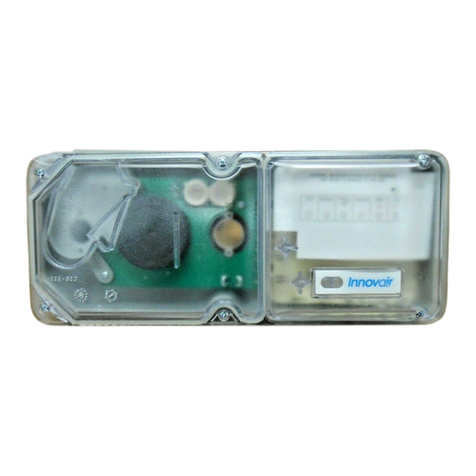
Johnson Controls IR6003/7 User manual

IR Oil Mist/Smoke Detector
Features
• AutomaticSelfCalibration
• Range=2-30metres
• WeatherprooftoIP65
• CertifiedIntrinsicallySafeEExibIIBT5
• RobustDesign
• HeavyDutyMountingBracketavailable
• Independentbeamblockedoutput
• Cleaningstatusoutput
• Dualautomaticcompensation
IR6003/7
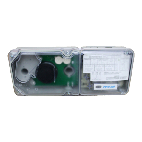
The IR6003/7 Oil Mist/Smoke Detector
has been specially designed to be highly
sensitive to the presence of oil & kerosene
mists or smoke particles in the path of the
detector beam.
Thedetectorhasbeendevelopedforuseinenclosed
oilrigwellheadareas,generatorroomsandturbine
enclosures.Thedetectorautomaticallycompensatesfor
contaminationofthedetectorlensesandsignalswhen
apointisreachedwherefurtherdeteriorationcannotbe
toleratedandthelenserequirescleaning.
Twolevelsofalarmstatusareprovided.Alowlevelalarm
andahighlevelalarm.Thereisalsoabeamblocked
statusprovidedintheeventthatthebeamisinterrupted.
Thedetectorisintendedtobeusedtogetherwithour
P-UIM6005/2whichwillprovidethedetectorasvolt-free
contacts.
PSF330JC_Time_Saver_Mount.indd 1 27/08/2019 17:23:12

10deg.Max
10M-Type1Reflector
30M-Type2Reflector
Functional Description
Initialisation:
Whenthedetectorisswitchedon,its
LEDindicatorblipsontosignifypower
up.Duringthefirst10secondsthe
detectorperformsautocalibrationto
establishthequiescentobscurationlevel.
Please note:Itisimportantthatthe
beampathisclearedtoahealthystate
(noobscuration)priortoresettingthe
detector.Ifthebeampathisnothealthy,
thedetectorwillrecalibratetothe
currentlevelofobscurationinturn
reportingfalsealarm/faultconditionsas
thepathclears.Ifobscurationishigh(dir-
tylensesoroil/smokeispresent)then
thedetectorwillnotbeabletoestablish
operationalstateandwillreportaclean
fault(LEDpulsesonfor4sec)oralife
fault(LEDisilluminatedcontinuously).
TheP-UIMwilllatchthefaultcondition
andthedetector/P-UIMwillrequire
resetting.
Alarm Level Detection:
Thedetectormonitorstheobscuration
levelwithinthebeampathandwhenit
detectsalossof0.5dBitlatchesalow
levelalarmcondition.Ifthelossis
maintainedwithinthe0.5to<1.5dB
bandduringthesubsequent15second
alarmmonitoringperiod,alowlevel
alarmwillthenbereported(LEDwill
pulseOn/Offfor30seconds).Iftheloss
exceeds1.5dBthenahighlevelalarmis
latchedandthisstatuswillbereported
(LEDpulsesOn/Offfor2minutes)atthe
earliest8secondsfromthebeginningof
thealarmmonitoringperiod.Ifthehigh
leveloccurssubsequenttotheinitial8
secondofthealarmmonitoringperiod
andbeforeatotalof15secondshas
elapsed,thehighlevelalarmwillbe
latchedandreportedimmediately.Please
Note:Iftheleveloflossduringthealarm
conditionmonitoringperiodfallsbelow
0.5dB,thelatchedalarmlevelwillreset
andthedetectorwillcontinuetomonitor.
Beam Block:
Ifthelevelofobscurationincreases
suddenlytoahighleveloflossabeam
blockedstatuswillbelatchedandifthe
levelismaintainedfor60seconds,Beam
Blockedwillbereported(LEDflashesON
for2seconds).Ifthebeamblockedlevel
ofobscurationclearsformorethanafew
secondsduringthe60secondperiod
monitoringperiod,thedetectorwill
returntoitsnormaloperatingstate.
Dual Automatic Compensation:
Thedetectorautomaticallycompensates
forgradualdetectorlenscontamination
andalsocompensatesforthemorerapid
environmentalchanges(eg.Temperature
Change).Thedetectorwillreportaclean
fault(LEDFlashesonfor4seconds)
once.Ifthedetectorisnotcleaneditwill
continuetooperateuntilalifefaultis
detected(LEDonsteady)atwhichpoint
thedetectorlatchedtoanoffcondition.
Thedetectormustbecleanedandreset
oncethelifefaulthasbeendetected.
Installation Procedure
Toinstallthedetector,findan
unobstructedpath,ideallyabovehead
heightthatcoverstheareatobe
monitored.Whenchoosingthebeam
paththedirectionofanyprevailingair
currentsshouldbenotedtoassessthe
directionthatanyoilmistwouldbe
conveyed.
Itshouldbenotedthatthebeammust
notbewithin500mmofanywallor
partition.Theoperatingrangeis2-50
metres.
Thereflectorsheetmustbemountedon
aflatsurface(selfadhesivebacking)such
thatthedetectorandreflectorare
alignedhorizontallyandvertically.To
assistinthisprocedureatoolisavailable
(01-33-21)toensurethedetectorbeamis
focusedcentrallyonthereflector.The
alignmenttoolintensifiestheIRbeam&
convertsitsimagetovisiblelight.Dueto
thenatureofoperationofthealignment
tool,itisrecommendedthatitshould
usedinsubduedlightconditions.The
physicsofthereflectorconstruction,
enablethereflectortobeupto10
degreesoutofalignmentinanyone
planeasdetailedinthefollowing
diagram:
IR Oil Mist/Smoke Detector
IR6003/7
PSF330JC_Time_Saver_Mount.indd 2 27/08/2019 17:23:13
IR Oil Mist/Smoke Detector
IR6003/7
Thisdiagramshowsthedetector
connectedtoalocaljunctionboxviathe
flyinglead(01-33-14).Thelocaljunction
boxwillrequireconnectingtoourP-UIM
viaasuitablesafetybarrierwhich
providedthenecessarydetectortouser
equipmentinterface.(Fordetailssee
PowerUIM6005/2Datasheet01-33-22)
Fordetailsonhowtomountthedetector
refertoheavydutymountingbracket
Datasheet(01-33-24)
Distance Reflector Size Type
2to10M 0.6x0.6M(1x6Mx0.6M) 1
10to30M 1.2x1.2M(2x1.2Mx0.6M) 2
Commissioning
Oncethedetectorhasbeeninstalled
correctlybyconnectingittothehazard
monitoringsystemviatheP-UIM,the
usershouldpowerupthedetectorloop
andperformthefollowingconfidence
checks:
1. ThedetectorLEDblipsOnbrieflyasit
receivespowerfromtheP-UIM.The
P-UIMLifeindicatorisflashing.
2.AlsoOutputOnindicatorshouldbe
Onsteady,allotherindicatorsare
extinguished.
3.Wait20secondsandcheckthatthe
statusdetailedinstep1above
remainsunchanged.
4.Blockthebeampathofthedetector
for1minuteandcheckthatthe
detectorsignalsabeamblockedstate
(LEDflashesOnfor2seconds).The
P-UIMBeamBlockedindicatorislit
steady.Nowremovetheobstruction
fromthedetectorspath.
5.Initiateashortresetandcheckthat
theP-UIMreturnstothestatus
detailedinstep1.
6.Initiatealongresetwiththebeam
pathblockedandcheckthatthe
detectorindicatesaLifeFault(LEDis
litsteady).TheP-UIMLifeindicatoris
litsteady.Nowremovethe
obstructionforthedetectorspath.
7. Initiatealongresetandcheckthatthe
P-UIMreturnstothestatusdetailedin
step1.
Operational Parameters
ThedetectorreceivesitsDCsupplyfrom
theP-UIMandprovidesstatusreportsto
theP-UIMasfollows:
• Anormal/healthydetectorinput
conditionisindicatedwhenthe
currentis>20mAand<32mA
(normally25mA).TheLEDonthefront
ofthedetectorwillbeextinguished.
• Alow alarmconditionisindicated
whenthecurrentpulsesfromnormal
to42mAwitha1secondequalmark
spaceratioforaperiodof30seconds.
• Ahigh alarmisindicatedwhenthe
whenthecurrentpulsesfromnormal
to42mAwitha0.5secondequal
markspaceratioforaperiodof2
minutes.
• Abeam blockedconditionis
indicatedwhenthecurrentswitches
fromnormalto17mAforaperiodof
2seconds
• Acleaning faultconditionisindicated
whenthecurrentswitchesfrom
normalto17mAforaperiodof4
seconds
• Alife faultconditionisindicated
whenthecurrentfallsto17mAfor>5
seconds.
PSF330JC_Time_Saver_Mount.indd 3 27/08/2019 17:23:13

IR Oil Mist/Smoke Detector
IR6003/7
Technical Specificaions
Electrical:
OperatingVoltage: 24V(viaP-UIM)
QuiescentCurrent: 25mA
AlarmCurrent: 80mA(max)
BeamLength: 2to30metres
Mechanical:
Dimensions: W165xH125xD165mm
Weight: 0.96kg
Material: NoryllGTXGrade810
Environmental:
OperatingTemperature: -10to+55°C
HousingProtection: IP65
BASEEFA9Cert: BAS02ATEX2313X
EExibIIBT5
SIRACert IECExSIR14.0009X
II2GExibIIBT5Gb
Accesories
FlyingLead: 01-33-14
ReflectorType1: 01-33-05
ReflectorType2: 01-33-10
ReflectorType3: 01-33-11
P-UIM: 01-33-22
0-20mAAdapter: 01-33-22A
HeavyDutyM/B: 01-33-24
U-Bracket: 01-33-12
IRAlignmentTool: 01-33-21
IRTestFilm: 01-33-26
Detector Monitoring Characteristics
Detector Life Compensation Characteristics
PSF330JC_Time_Saver_Mount.indd 4 27/08/2019 17:23:14

IR Oil Mist/Smoke Detector
IR6003/7
Flying Lead Connections
ClientsViewofConnector
Ex Requirements
InordertomaintaintheEExcertifiedstatus
oftheequipmentthefollowingrequirements
mustbemet:
• Theapparatuscannotberepairedand
mustbereplacedbyanequivalentunit.
• Theapparatusisnotintendedtobe
exposedtodustconditions.
• Theequipmentwheninstalledin
accordancewiththeinstruction
manualwillnotbesubjectedto
mechanicalstress.
• Theequipmentshouldnotbe
installedwhereitmaybesubjected
tomechanicalandthermalstressor
whereitmaybeattackedbyexisting
orforeseeableaggressive
substances.
Number Name General Count Number Name General Count
1Shell 150 19 TechnipMar. 5
2BP 250 20 Det-tronics 30
3How 50 21 HESS 4
4Total 20 22 DebylLtd. 6
5BNFL 823 NorthSea 50
6Micropack 10 24 STATOil 15
7Maersk 10 25 DutchNavy 16
8Silvertech 30 26 PrudhoeBay 10
9ICS 60 27 FPSO 30
10 Reliance 328 HRL/Centrica 20
11 Paxman 16 29 Airbus 8
12 GEC 830 Kvaerner 4
13 EGT 20 31 Preussag 30
14 Pagannini 60 32 Zellweger 2
15 Thorn 833 CooperEne. 30
16 Olsen 234 Honeywell 10
17 Amec 435 SaipemSA 20
18 Thomassen 10 36 Autronica 15
Client List
PSF330JC_Time_Saver_Mount.indd 5 27/08/2019 17:23:14

IR Oil Mist/Smoke Detector
IR6003/7
©2019JohnsonControls.Allrightsreserved.
Allspecificationsandotherinformationshownwerecurrentasofdocumentrevision
dateandaresubjecttochangewithoutnotice.
PSF303JCIssue–108/19
www.johnsoncontrols.co.uk
Therearemanyothercompanieswhointegrateouroilmist
detection
equipmentintotheresafetysystems,Thesecanrangefrom:
- HeavyIndustrialArease.g.EngineRooms
- HazardousAreas
- Warehouses
- MarineApplications
- OilRigs
- FSPO’se.g.ShellBONGA
- Turbines
- HyraulicPowerUnits
- Plusmanymore……
PSF330JC_Time_Saver_Mount.indd 6 27/08/2019 17:23:14
Table of contents
Other Johnson Controls Smoke Alarm manuals

Johnson Controls
Johnson Controls DH300RPL User manual

Johnson Controls
Johnson Controls METASYS B501BHJ User manual

Johnson Controls
Johnson Controls METASYS DH500 Series User manual

Johnson Controls
Johnson Controls 2951JR User manual

Johnson Controls
Johnson Controls Metasys 2400 User manual

Johnson Controls
Johnson Controls DH300PL User manual
Popular Smoke Alarm manuals by other brands

Jung
Jung FRWM 100 WW instruction manual

Cofem
Cofem EYEHOME+ quick guide

BURGprotect
BURGprotect Smoke 2050 user manual

Notifier
Notifier NFX-OPT Installation and maintenance instructions

merten
merten MEG5470-2119 operating instructions

System Sensor
System Sensor FTX-P1 Installation and maintenance instructions