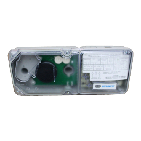
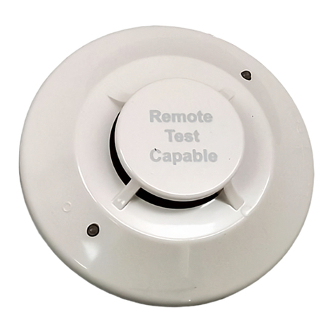
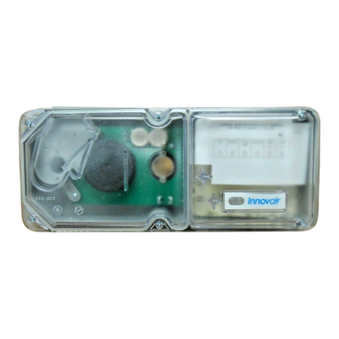
Johnson Controls METASYS DH500 Series User manual

Fire Initiating Devices and Notification Appliances Technical Manual 408
Intelligent Products Section
Technical Bulletin
Issue Date 1095
© 1995 Johnson Controls, Inc. 1
Code No. LIT-408095
Introduction Page 3
●
General Description 4
Installation Procedures 9
●
General Information 9
●
Installation 10
●
Mounting 11
●
Wiring Installation Guidelines 16
Testing and Maintenance Procedures 21
●
Testing 21
●
Testing Alarms 22
●
Maintenance 26
●
Detector Test Log 30
●
Limitations 31
DH500 Series Intelligent Air Duct Smoke Detector

2 Intelligent Products—DH500 Series Intelligent Air Duct Smoke Detector

Intelligent Products—DH500 Series Intelligent Air Duct Smoke Detector 3
Introduction
This document contains important information about installing and
operating the Johnson Controls DH500 series intelligent air duct smoke
detector. If you install this detector for someone else to use, you must
leave a copy of this document with the user. The DH500 series duct
detector is listed per UL 268A.
These instructions provide information regarding mounting, wiring,
installation, testing, and maintenance. Follow only those instructions that
apply to the model you are installing.
Before you install any DH500 series intelligent air duct smoke detectors,
read and be familiar with:
●the control panel system installation manual
●the requirements of the authority having jurisdiction
●National Fire Protection Association (NFPA)-72-National Fire
Alarm Code and NFPA-90A, Installation of Air Conditioning and
Ventilation Systems
●System Sensor Guide for Proper Use of System Smoke Detectors
Technical Bulletin in the Fire Initiating Devices and Notification
Appliances Technical Manual (FAN 408), which provides detailed
information on detector spacing, placement, zoning, wiring, and
special applications
●or, for non-United States installations, applicable codes and standards
specific to country and locality of installation
Failure to follow these directions may result in failure of this device to
report an alarm or trouble condition or respond properly to an alarm
condition. Johnson Controls is not responsible for devices that have been
improperly installed, tested, or maintained by others.
As is the case with all installations under NFPA, Underwriters
Laboratories of Canada (ULC), or Canadian Electrical Code classification,
final written approval of permissible operation and configuration rests
with the authority having jurisdiction.
4 Intelligent Products—DH500 Series Intelligent Air Duct Smoke Detector
A Heating, Ventilating, and Air Conditioning (HVAC) system supplies
conditioned air to virtually every area of a building. Smoke introduced
into this air duct system will be distributed to the entire building. Smoke
detectors designed for use in air duct systems are used to sense the presence
of smoke in the duct and initiate action to prevent the spread of smoke.
The DH500 series air duct detector housings are used with the intelligent
1551J ionization detector heads and 2551J photoelectronic detector heads.
These two smoke detection methods are combined with an efficient
housing design that samples air passing through a duct and allows early
detection of a developing hazardous condition. When sufficient smoke is
sensed, an alarm signal is initiated at the fire control panel monitoring the
detector, and appropriate action can be taken to shut off fans, blowers, and
change over air handling systems. This can prevent the distribution of
toxic smoke and fire gases throughout the areas served by the duct system.
There are two models of the duct smoke detector: the DH500J, which has
auxiliary relays that allow for optional fan control, alarms, etc. and
operates on 120/240 VAC or 24 VAC/DC; and the DH502J, which has no
auxiliary relays and operates on 24 VDC. Both models have two Form-C
alarm activated relay output contacts that are available for local control
purposes and two Light Emitting Diodes (LEDs) on each detector latch on
to provide a local alarm indication. Remote alarm indication is made
possible by utilizing the 12 volt alarm output to connect to the RA400Z
remote annunciator. By using the correct code commands from the fire
alarm control panel, the duct detector can be tested and the alarm can be
reset. See the panel instructions for details.
Table 1: Contents of the Duct Detector Housing Kit
Number Item
1Complete Housing Base and Cover Assembly
2No. 10 Sheet Metal Mounting Screws
2Sampling Tube Filters
1Test Magnet
1Drilling Template
25/16-in. O-rings
2Foam Gaskets
4No. 6 Self-tapping Mounting Screws for the Sampling Tube
1Filter Adapter
1Inlet Tube End Plug
2No. 10 Speed Nuts
General
Description

Intelligent Products—DH500 Series Intelligent Air Duct Smoke Detector 5
Order the inlet sampling tube and a smoke detector head (1551J for
ionization or an 2551J for photoelectronic) separately. The sampling tube
selected must be the correct length for the width of the duct where it will
be installed. To determine the inlet tube required for different duct widths,
see Table 4: Sampling Inlet Tubes in the Mounting, Mount Duct Housing
section of this technical bulletin.
Figure 1: Duct Detector Housing Kit
Foam
Gasket
Detector Base
Exhaust Filter
Adapter
Conduit Holes
Detector Head
(
Supplied Separatel
y
)
Samplin
g
Tube
Filters
Cover
Screws
Samplin
g
Tube
Mountin
g
Screws
DuctDetector
Cover
(
Clear Plastic
)
Tube End
Plu
g
Duct Detector
Housin
g
Terminal Strip
PC Board
Insulator
dh500
j
-1
Test Ma
g
net
Inlet Samplin
g
Tube
(
Supplied Separtel
y
)
O-rin
g
s
Housin
g
Mountin
g
Screws

6 Intelligent Products—DH500 Series Intelligent Air Duct Smoke Detector
Table 2: Specifications Summary
Specifications
Length 14.5 in. (368.3 mm)
Width 5 in. (127 mm)
Depth 4 in. (101.6 mm) DH500J
3.5 in. (88.9 mm) DH502J
Weight 4 lb (1820 g) DH500J
2 lb, 8 oz (1130 g) DH502J
Operating Temperature Range 32 to 120°F (0 to 49°C)
Operating Humidity Range 10 to 93% Relative Humidity
Duct Air Velocity 300 to 4000 ft/min. (91.4 to 1219.2 m/min.)
Relay Contacts (DH500J) Two Alarm Activated Form-C
Minimum contact current must be greater than 500 mA.
10A @ 30 VDC
10A @ 277 VAC (0.75 power factor)
240 VA @ 240 VAC (0.4 power factor)
1/8 hp @ 120 VAC
1/4 hp @ 240 VAC
Accessories Part Number
Remote LED RA400Z
Piezo Alert Sounder PA400
Replacement Filters F36-05-00
Magnet M02-04-00
End Plug For Sampling Tube P48-21-00
Installation Kit (Parts bag) A2650-01 DH500J
A2650-00 DH502J
Photoelectronic Replacement
Screen RS24
Ionization Replacement Screen RS14
Sensitivity Test Kit MOD400 or MOD400R
Ionization Cover Removal Tool CRT400
Remote Test Station RTS451
Calibrated Test Card
(for photo units only) R59-18-00
Sampling (Inlet) Tubes
Tube Outside Duct Width
ST-1.5 1 to 2 ft (300 to 600 mm)
ST-3 2 to 4 ft (600 to 1200 mm)
ST-5 4 to 8 ft (1200 to 2400 mm)
ST-10 8 to 12 ft (2400 to 3700 mm)DH500J
8 to 10 ft (2400 to 3700 mm)DH502J

Intelligent Products—DH500 Series Intelligent Air Duct Smoke Detector 7
Table 3: Power Supply Electrical Ratings
DH500J (With Relays)
Power
Requirements 120 VAC
102-132 mA
RMS Maximum
240 VAC
204-264 mA
RMS Maximum
24 VAC
20.6-26.4 mA
RMS Maximum
24 VDC
20-30 mA
DC Maximum
Device Standby Alarm Standby Alarm Standby Alarm Standby Alarm
DH500J 44 52 25 30 65 182 26 87
PA400* -- 3 -- 1.5 -- 29 -- 15
RA400Z* -- 1.5 -- 1 -- 17.3 -- 7
RTS451* -- 1.5 -- 1 -- 17.3 -- 7
RTS451** 11.5 13 5.5 6.5 140 157 71 78
* All accessory currents are additional to DH500J. There are no additional currents for accessories in standby.
** RTS451 when the magnet is held in place to initiate an alarm.
Output Maximum Load Rating
24V 80 mA
12V 20 mA
DH502J (Without Relays)
Voltage Range 15-28 VDC peak
Standby Current (nominal) 200 Microampere at 24 VDC
Power-up Surge at Maximum Rated Voltage 1.5 Milliampere/second
LED Current (nominal) 6 Milliamperes at 24 VDC

8 Intelligent Products—DH500 Series Intelligent Air Duct Smoke Detector
Smoke detector models 1551J and 2551J can be used with the DH500
series if the following constraints are observed:
1. There may be a limit to the number of devices per Signaling Line
Circuit (SLC) that can have their LEDs latched on.
The actual number of devices is determined by the control panel and
its ability to supply LED current. As seen with software Release 1
(Firmware Group M34 or earlier) for the IFC-2020 system, the control
panel stops latching device LEDs on after four device detectors
indicate an alarm.
The maximum number of devices that can be latched in an alarm state
at one time is four. If more than the maximum number of devices are
on the same SLC, do not use the DH500 series for control purposes.
Control for duct applications would need to come directly from the
control panel or by using control modules.
2. For the IFC-1010 systems with any level of software and for the
IFC-2020 systems that use Release 2 (Firmware Group M35) or
higher and have intelligent detectors and modules with the R4
marking on their label:
●The LED restriction does not apply.
●All LEDs may be latched on.
●Consult the IFC product line programming manuals for
additional information.
3. When FC-2000 control panels are used with AM-200 modules, they
may ignore the LED restriction by selecting the “FL” full LED
control. Consult the AM-200 manual for further information.
4. The duct control circuitry (auxiliary relay contacts and 12 volt alarm
output) may operate (change states) if the detector is tested and the
LED is turned off for more than four seconds.
5. If the time the LED is latched on is less than four seconds, the relay
and remote annunciator control circuitry of the DH500 series will not
operate.
6. The following systems must use the 1551J with the DH500 series
models when high sensitivity is selected:
●FC-2000 panels with AM-200 modules
●IFC-2020 software Release 1 (Firmware Group M34 or earlier)
Programming
Requirements for
Intelligent
System Control
Panels

Intelligent Products—DH500 Series Intelligent Air Duct Smoke Detector 9
Installation Procedures
This section contains installation information for DH500 series intelligent
air duct smoke detectors. Instructions are given for wiring the detector,
and basic installation information is provided.
!
CAUTION: Equipment damage hazard. This device cannot
operate without electrical power. This device
will not sense smoke unless the ventilation system
is operating.
Frequently, fire situations may cause an interruption of power to the
detector. The system safeguards should be discussed with your local fire
protection specialist.
For this detector to function properly, it must be installed according to the
instructions in this document. The detector must be protected from the
elements and operate within all electrical and environmental specifications
described in this technical bulletin. Failure to comply with these
requirements may prevent the detector from activating when smoke is
present in the air duct.
General
Information

10 Intelligent Products—DH500 Series Intelligent Air Duct Smoke Detector
1. Verify duct air flow direction and velocity.
2. Drill the mounting holes.
3. Mount duct housing.
4. Install the inlet tube.
5. Complete the field wiring.
6. Install the filters.
7. Perform the detector check.
8. Install the cover.
9. Perform the final system check as described in the Testing section of
this technical bulletin.
The DH500 series is designed to be used in air handling systems having
air velocities of 300 to 4000 feet per minute.
1. Be sure to check engineering specifications to ensure that the air
velocity in the duct falls within these parameters.
2. If necessary, use a velocity meter to check the air velocity in the duct.
Installation
Installation
Sequence
Verify Duct Air
Flow Direction
and Velocity

Intelligent Products—DH500 Series Intelligent Air Duct Smoke Detector 11
1. Remove the paper backing from the drilling template.
2. Affix the template to the air duct at the desired mounting location
oriented on the duct (Figure 4).
3. Make sure the template lies flat and smooth on the air duct.
4. Center punch hole targets and remove the template.
5. Drill the holes as indicated on the template.
6. Slide the two speed nuts over the two small holes (Hole A) next to the
sampling tube bushing holes (Hole B) previously drilled in the duct
(Figure 2).
7. Mount the detectors in or on air ducts at least six duct widths
downstream from any duct openings, deflection plates, sharp bends,
or branch connections.
Note: Where it is physically impossible to locate the detector
accordingly, the detector can be positioned closer than six duct
widths but as far as possible from the opening, bend, or
deflection plates.
1. Remove the duct housing cover.
2. Slide the foam gaskets over the tube bushings (Figure 3).
3. Make sure the two small holes in the gaskets line up with the two duct
housing mounting holes.
4. Put one 5/16 inch O-ring over each of the two No. 10 sheet metal
screws.
5. Use the two sheet metal screws to secure the duct housing to the duct.
6. Do not overtighten the screws.
Mounting
Drill the Mounting
Holes
Mount Duct
Housing

12 Intelligent Products—DH500 Series Intelligent Air Duct Smoke Detector
dhfig2
Hole A
Hole B
Duct Wall
Speed Nut .....
Figure 2: Speed Nut Mounting Location
dhfi
g
2a
DuctDetector
Housin
g
ExhaustTube
(
Extension Bushin
g
)
Foam Gaskets.....
O-rin
g
s
Mountin
g
Screws
Screw Holes For Attatchin
g
Detector Housin
g
to Duct
Inlet Samplin
g
Tube Bushin
g
Figure 3: Installation of Foam Gaskets
over Sampling Tube Bushings
Table 4: Sampling Inlet Tubes for the DH500J and the DH502J
Tube Outside Duct Width
ST-1.5 1 to 2 ft (300 to 600 mm)
ST-3 2 to 4 ft (600 to 1200 mm)
ST-5 4 to 8 ft (1200 to 2400 mm)
ST-10 8 to 12 ft (2400 to 3700 mm) DH500J
8 to 10 ft (2400 to 3700 mm) DH502J

Intelligent Products—DH500 Series Intelligent Air Duct Smoke Detector 13
Air Flow
Direction
Duct
Detector
Housin
g
Air Flow
Direction
Air Flow
Direction
Air Flow
Direction
dhfi
g
4
Dots Indicate Position of
Samplin
g
Tube Holes
Inlet
Tube
Exhaust
Tube
Duct
Detector
Housin
g
Duct
Detector
Housin
g
Duct
Detector
Housin
g
Inlet
Tube
Exhaust
Tube
Inlet
Tube
Exhaust
Tube
Figure 4: Tube Mounting Configurations with Varying Air Flow
Direction and Orientation of Detector Housing -
Vertical as well as Horizontal Mounting is Acceptable
The sampling inlet tube is identified by a series of air inlet holes on the
tube (Figure 5). This tube must be purchased separately. Order the
correct length for the width of the duct where it will be installed as
described in Table 4: Sampling Inlet Tubes in this technical bulletin. The
exhaust tube is molded into the base of the duct housing.
1. Install the inlet tube in the inlet sampling tube bushing located in the
center of the duct detector housing (Figure 3).
2. Face the air inlet holes into the air flow.
Note: To assure proper installation, the tube mounting flange is
marked with arrows.
3. Mount the inlet tube so that the arrows point into the air flow.
Air flow and the various combinations of duct detector and tube
mounting configurations are shown in Figure 4.
Install the Inlet
Tube

14 Intelligent Products—DH500 Series Intelligent Air Duct Smoke Detector
dhfig3
Air Flow Direction
Sample Inlet Holes
Tube
End Plu
g
.....
Arrows should
face into
air flow.
Figure 5: Air Duct Detector Inlet Sampling Tube
Installation for Ducts less than Eight Feet Wide
1. If the inlet tube is longer than the width of the air duct:
Drill a 3/4 inch hole in the duct directly opposite the hole already cut
for the inlet tube.
2. If the inlet tube is shorter than the width of the air duct:
Install the end cap into the inlet tube (Figure 5).
3. Slide the inlet tube into the bushing located in the center of the duct
detector housing.
4. Position the tube so that the arrows point into the air flow.
5. Secure the tube flange to the housing bushing with the two No. 6
self-tapping screws.
6. For tubes longer than the width of the air duct, extend the tube out of
the opposite side of the duct.
7. If there are more than two holes in the section of the tube extending
out of the duct, select a different tube length as described in
Table 4: Sampling Inlet Tubes in the Mounting, Mount Duct Housing
section of this technical bulletin.
8. Otherwise, trim the end of the tube protruding through the duct so that
one to two inches of the tube extends outside the duct.
9. Plug this end with the tube end plug, and tape close any holes in the
protruding section of the tube.
10. Seal the duct when the tube protrudes.
11. Support any inlet tube over three feet long on the opposite side of the
duct detector housing.

Intelligent Products—DH500 Series Intelligent Air Duct Smoke Detector 15
!
CAUTION: Equipment damage hazard. In no case should
more than two air inlet holes be cut off the tube.
There must be a minimum of ten holes in the tube
exposed to the air stream.
Installation for Ducts more than Eight Feet Wide
To install inlet tubes in ducts more than eight feet wide, work must be
performed inside the air duct. Sampling of air in ducts wider than
eight feet is accomplished by using the ST-10 inlet sampling tube.
1. Drill a 3/4 inch hole in the duct directly opposite the hole already
drilled for the inlet tube.
2. Slide the inlet tube into the bushing located in the center of the duct
housing.
3. Position the tube so that the arrows point into the air flow.
4. Secure the tube flange to the housing bushing with the two No. 6
self-tapping screws.
5. From inside the duct, couple the other section of the inlet tube to the
section already installed using the 1/2 inch conduit fitting supplied.
Make sure that the holes on both of the air inlet tubes are lined up
facing the direction of air flow.
6. Trim the end of the tube protruding through the duct so that one to
two inches of the tube extends outside the duct.
7. Plug this end with the tube end plug, and tape close any holes in the
protruding section of the tube.
8. Be sure to seal the duct when the tube protrudes.
9. Ensure that any tube over three feet long that does not protrude
through the duct on the side opposite the housing is supported by
other means.
For an alternate method of using the ST-10:
1. Use two ST-5 inlet tubes.
2. Remove the flange from one of the tubes and install as described in
the Installation for Ducts more than Eight Feet Wide section of this
technical bulletin.
3. After the installation, use electrician’s tape to close off some of the
sampling holes so that there is a total of 12 holes spaced as evenly as
possible across the width of the duct.
Air currents inside the duct may cause excessive vibration. This vibration
can slowly open the seal around the tube and permit air to escape.

16 Intelligent Products—DH500 Series Intelligent Air Duct Smoke Detector
To prevent this from occurring, use a three inch floor flange, available at
most plumbing supply houses.
This flange/connector mounting technique makes the initial installation
easier because a 1 inch to 1-1/4 inch hole may be drilled where the
flange/connector will be used. It is easier to push the inlet tube through
the larger hole.
Interim Modification of Inlet Sampling Tubes
There may be situations where duct widths are not as specified for the
installation. In such cases, it is permissible to modify an inlet sampling
tube that is longer than necessary to span the duct width.
Note: This procedure should only be used in an emergency, and it is
not intended as a permanent substitute for ordering the correct
length tubes.
1. Use a 0.193 inch diameter (No. 11) drill, and add the appropriate
number of holes so that the total number of holes exposed to the air
flow in the duct is 10 to 12.
2. Space the additional holes as evenly as possible over the length of
the tube.
All wiring must be installed in compliance with the National Electrical
Code and the local codes having jurisdiction, using the proper wire
gauges. The conductors used to connect smoke detectors to control panels
and accessory devices should be color-coded to reduce the likelihood of
wiring errors. Improper connections can prevent a system from
responding properly in the event of a fire.
For Signaling Line Circuit (SLC) wiring (the wiring between the control
panel and interconnected detectors), it is usually recommended that
single-conductor wire be no smaller than No. 16 AWG (1.5 square mm)
and that 2- or 3-conductor wire be no smaller than No. 18 AWG
(1.0 square mm). To accommodate voltage line loss, a larger wire size
may be needed. See the control panel documentation of SLC sizing
information. Solid conduit connections may be used, if desired.
The last foot or so of conduit should be flexible steel conduit (available in
electrical supply houses), which facilitates easier installation and puts less
strain on the conduit holes in the housing.
Smoke detectors and alarm system control panels have specifications for
allowable SLC resistance. Consult the control panel manufacturer’s
specifications for the total SLC resistance allowed for the particular model
control panel being used before wiring the detector SLC.
Wiring
Installation
Guidelines

Intelligent Products—DH500 Series Intelligent Air Duct Smoke Detector 17
In order for the alarm controlled relay to operate, a separate power supply
must be connected to the DH500J. The power on the SLC is not adequate
to operate the relay without supplying additional power. A separate power
supply is not required with the DH502J.
The DH500J is designed for easy wiring. The housing provides a terminal
strip with clamping plates.
To make wire connections:
1. Strip approximately 1/2 inch of insulation from the end of the wire.
2. Tape back and isolate the SLC cable shield from contact with any
metal object, but assure the shield continuity is preserved over the
entire length of the SLC.
3. Slide this bare end under the plate.
4. Tighten the clamping plate screw.
The DH500J operates from 120/240 VAC or 24 VAC/DC to operate
auxiliary functions (Figure 6).
For the 4-wire operation of the DH500J for alarm controlled relay and
auxiliary function activation:
1. Cut the jumper wire J5, located between the two terminal strips on the
printed circuit board (Figure 6), to ensure proper power supply
supervision when the detector is used in a 4-wire application
(relay circuit is being used to control fans and dampers) and a separate
power supply is connected to the DH500J to power the alarm
activated control relay.
2. Leave the jumper wire J5 in place when the detector is used in a
2-wire application (relay control is not being used for any control of
fans and dampers).
To complete the wiring for 110/120 VAC 4-wire operation:
1. Connect the power supply wires to terminals 15 and 16 (Figure 6).
2. If 220/240 VAC operation is preferred, connect the power supply
wires to terminals 16 and 17.
Wiring the
DH500J
120/240 VAC
Operation

18 Intelligent Products—DH500 Series Intelligent Air Duct Smoke Detector
To complete the wiring for 24 VAC or DC 4-wire operation:
1. Connect the power supply wires to Terminals 7 and 8.
2. Polarity is not important.
Table 5: Accessory Current Loads at 24 VDC
Device Standby Alarm
PA400 0 mA 15 mA Maximum
RA400Z 0 mA 7 mA Maximum
RTS451 0 mA* 7 mA Maximum*
* When initiating an alarm, the RTS451 requires 71 mA maximum in pre-alarm and
78 mA maximum in alarm. Nominal standby current is 0 mA. The alarm current
is 7 mA maximum when test magnet is removed.
Table 6: Accessory Total Current Loads
Any combination of accessories used to give the total current loads:
Standby State 30 mA or less
Alarm State 80 mA Maximum
24 VDC (Terminals 3 and 6)
20 mA Maximum
12 VDC alarm contacts (Terminals 2 and 6)
24 VAC/DC
Operation

Intelligent Products—DH500 Series Intelligent Air Duct Smoke Detector 19
Figure 6: Wiring Diagram
Most duct installations are subject to dust accumulation. Detector housing
filters remove a large percentage of this contamination, but cannot remove
all of it. Dust inside the duct detector causes problems.
●Very fine particles of dust can enter the detector sensing chamber and
cause the unit to go into alarm.
●The accumulation of dust and dirt necessitates a more frequent
periodic cleaning schedule, which can result in substantial cost and/or
down time.
Disposable sampling tube filters can greatly reduce the nuisance alarms
caused by dust, and can also significantly extend the maintenance interval.
To install the sampling tube filters:
1. Press the filter adapter into the exhaust tube.
2. Push the filter onto the adapter tube on the left (Figure 7).
3. Install the other filter over the end of the inlet sampling tube.
4 5 6 7 8 9 10 11 12 13 14 15 16 17
Alwa
y
s run auxiliar
y
control
wirin
g
in separate conduit.
Communication
Line
From Panel
Communication
Line to Reset
of S
y
stem
1
Jumper
J5 K2
2
3
Note: For power suppl
y
wires,
polarit
y
is not important.
Jumper wire
(
J5
)
is re
q
uired to be
intact for 2-wire
applications onl
y
.
Cut J5 for 4-wire
power supervision.
240 VAC
120 VAC
Duct Detector
DH500J
Alarm Si
g
nal 2
6
AUX Power
RA400Z
(
Optional
)
Remote
(
LED
)
Annunciator
R
E
D
dhfi
g
11
Note: Auxiliar
y
devices
(
RA400Z, PA400, and RTS451
)
and
auxiliar
y
control contacts will not function without auxiliar
y
power.
Duct Detector
DH500J PA400
(
Optional
)
Audible Alert
Alarm Si
g
nal
2
6
AUX Power
Note:
Note:
AlarmSi
g
nal 2
6
Duct Detector
DH500J
RTS451
(
Optional
)
Remote Test Station
Test
R
E
D
AUX Power
1
2
3
4
5
3
1
AUX Power
Test
Test
Reset
(
NotUsed
)
The RTS451 reset
cannot be used on the DH500J.
Install the Filters

20 Intelligent Products—DH500 Series Intelligent Air Duct Smoke Detector
Filters require periodic cleaning or replacement, depending on the amount
of dust and dirt accumulated. Visually inspect the filters at least quarterly;
inspect them more often if the dust accumulation warrants it.
The filters do not substantially affect smoke behavior even when they are
90% clogged. Quarterly visual inspection is usually enough to determine
if the filters should be replaced because only a high percentage of
contamination affects duct detector performance.
Foam
Gasket
Detector Base
Exhaust Filter
Adapter
Detector Head
Sampling Tube
Filters
Sampling Tube
Mounting Screws
dhfig13
Inlet Sampling Tube
Figure 7: Sampling Tube Filter Installation
1. Install the cover using the four screws that are fixed in the housing
cover.
2. Be certain filters are installed as described in the Install the Filters
section of this technical bulletin.
3. Make sure the cover fits into the base groove and all gaskets are in
their proper positions.
4. Tighten the four cover screws to 10 in·lb.
Perform Detector
Check
Install the Cover
Table of contents
Other Johnson Controls Smoke Alarm manuals

Johnson Controls
Johnson Controls DH300PL User manual

Johnson Controls
Johnson Controls 2951JR User manual

Johnson Controls
Johnson Controls METASYS B501BHJ User manual

Johnson Controls
Johnson Controls IR6003/7 User manual

Johnson Controls
Johnson Controls Metasys 2400 User manual

Johnson Controls
Johnson Controls DH300RPL User manual
Popular Smoke Alarm manuals by other brands

Teletek electronics
Teletek electronics SensoIRIS S130 Installation instruction

SMC Networks
SMC Networks SMCSM10-Z Guide

System Sensor
System Sensor Innovair DH200PL Installation and maintenance instructions

Nittan
Nittan Evolution-Advanced EV-DP instruction manual

Opal
Opal ATN062 user manual

System Sensor
System Sensor FAAST LT Control guide