Johnson Controls METASYS B501BHJ User manual

Fire Initiating Devices and Notification Appliances Technical Manual 408
Intelligent Products Section
Technical Bulletin
Issue Date 1095
© 1995 Johnson Controls, Inc. 1
Code No. LIT-408020
Introduction Page 3
●
General Description 4
Installation Procedures 7
●
General Information 7
●
Mounting 7
●
Wiring Installation Guidelines 8
Testing and Maintenance Procedures 11
●
Testing 11
●
Limitations 12
B501BHJ Plug-In Intelligent Sounder Detector Base

2 Intelligent Products—B501BHJ Plug-In Intelligent Sounder Detector Base

Intelligent Products—B501BHJ Plug-In Intelligent Sounder Detector Base 3
Introduction
This document contains important information about installing, wiring,
and operating Johnson Controls B501BHJ intelligent smoke and thermal
sounder detector bases. Follow only those instructions that apply to the
model you are installing. If you install this base for someone else to use,
leave a copy of this document with the user.
Before you install any B501BHJ sounder detector bases, read and be
familiar with:
●the control panel system installation manual
●the requirements of the authority having jurisdiction
●National Fire Protection Association (NFPA)-72-National Fire
Alarm Code
●System Sensor Guide for Proper Use of System Smoke Detectors
Technical Bulletin in the Fire Initiating Devices and Notification
Appliances Technical Manual (FAN 408), which provides detailed
information on detector spacing, placement, zoning, wiring, and
special applications
●or, for non-United States installations, applicable codes and standards
specific to country and locality of installation
Failure to follow these directions may result in failure of this device to
report an alarm or trouble condition or respond properly to an alarm
condition. Johnson Controls is not responsible for devices that have been
improperly installed, tested, or maintained by others.
As is the case with all installations under NFPA, Underwriters
Laboratories, Inc. (UL), Underwriters Laboratories of Canada (ULC), or
Canadian Electrical Code classification, final written approval of
permissible operation and configuration rests with the authority having
jurisdiction.
!
CAUTION: Equipment hazard. Do not use in potentially
explosive atmospheres. Do not leave unused wires
exposed.
In order to assure proper operation, this product should be applied as
specified in the applicable NFPA codes and in compliance with its
UL listing.
4 Intelligent Products—B501BHJ Plug-In Intelligent Sounder Detector Base
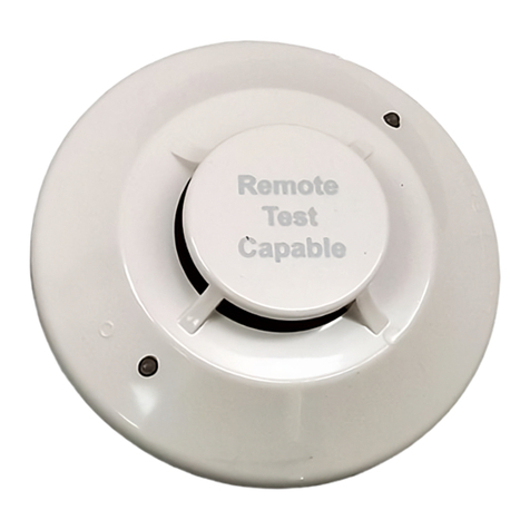
The B501BHJ sounder base is intended for use with intelligent fire alarm
systems and provides mounting and termination for the intelligent smoke
and heat detectors.
The sounder base requires an external 24 VDC supply with reverse
polarity capability. The connections for the external supply
(Terminals 1 and 2) and the communication SLC (Terminals 3, 4, and 5)
are isolated to prevent electrical interaction between them.
When the detector’s visible Light Emitting Diodes (LEDs) are latched on
for approximately ten seconds, the associated horn in the sounder base
sounds. A group of horns can be made to sound by reversing the polarity
of the external supply.
When not used as a supplementary evacuation system, the external
24 VDC supply shall be treated as a component of the main power supply
system and shall fall under the requirements of the main power supply
system per National Fire Protection Association (NFPA)-72-National Fire
Alarm Code.
Table 1: B501BHJ Terminals
Terminal Number Function
1External Supply Positive (+)
2External Supply Negative (-)
3Negative (-), Comm. SLC Line In
4Positive (+), Comm. SLC Line In and Out
5Negative (-), Comm. SLC Line Out
Terminals 3, 4, and 5 are used for the communication circuit.
General
Description

Intelligent Products—B501BHJ Plug-In Intelligent Sounder Detector Base 5
1
2
5
4
b501bh-a
3
Figure 1: Terminal Layout
Note: Johnson Controls smoke detectors are marked with a compatibility
identifier located as the last digit of a five digit code stamped on
the back of the product. Connect detectors only to compatible
control units as indicated in Johnson Controls compatibility chart,
which contains a current list of UL Listed control units and
detectors. A copy of this list is available in the Device
Compatibility Technical Bulletin located in the Fire Management
Accessories Manual (FAN 445).
!
CAUTION: Personal injury hazard. This device will not
operate without electrical power. Frequently, fire
situations may cause an interruption of power. The
system safeguards should be discussed with your local
fire protections specialist.
Note: Do not mix fire alarm system wiring in the same conduit with any
other electrical wiring.

6 Intelligent Products—B501BHJ Plug-In Intelligent Sounder Detector Base
Table 2: Specifications Summary
Specifications
Compatible Detector Heads 1251J Ionization Detector Head
2251J Photoelectronic Detector Head
1551J Ionization Detector Head
2551J Photoelectronic Detector Head
2551TJ Photo Detector Head with
Heat Sensor
5551J Thermal Detector Head
Base Diameter 6.0 in. (152.4 mm)
Base Height
(from the front of the backbox to front of
base)
2.3 in. (58.42 mm)
Weight 0.4 lb (182 g)
Operating Temperature Range 14 to 140°F (-10 to 60°C)
Operating Humidity Range 10 to 95% Relative Humidity
Communication/SLC Power Requirements
Current Draw from Remote Output of
Detector to Turn on Horn 700 uA Maximum
Sound Output Greater than 90 dBA measured in anechoic
room at 10 feet, 24 volts DC
85 dBA minimum measured in
UL 268 reverberant room

Intelligent Products—B501BHJ Plug-In Intelligent Sounder Detector Base 7
Installation Procedures
This section contains installation information for the B501BHJ sounder
detector base. Instructions are given for mounting the detector base, and
basic wiring information is provided.
Mount the B501BHJ directly to an electrical box, using the supplied
mounting kit (Figure 2).
1. The sounder base is 1.1 inches (27.9 mm) deep.
2. Electrical boxes must be 4 inches (101.6 mm) square by at least
1-1/2 (38.1 mm) inches deep (2-1/8 inches (54.0 mm) is
recommended).
A maximum space of 1/8 inch (3.2 mm) from the outside edge of the
electrical box to the inside edge of the drywall or ceiling tile is allowable.
moutbase
Mount B501BHJ
to electrical box.
4 inch
S
q
uare Box
Figure 2: Mounting
General
Information
Mounting

8 Intelligent Products—B501BHJ Plug-In Intelligent Sounder Detector Base
Note: Do not loop the SLC or external power supply wire under the
clamping plate (Figure 3).
All wiring must be installed in compliance with the National Electrical
Code and the local codes having jurisdiction, and must not be of such
length or wire size that would cause the base to operate outside of its
published specifications. The conductors used to connect smoke detectors
to control panels and accessory devices should be color coded to reduce
the likelihood of wiring errors. Improper connections can prevent a
system from responding properly in the event of a fire.
For SLC wiring (the wiring between interconnected detectors or modules),
it is recommended that the wire be no smaller than the No. 18 AWG
(1.0 square mm). Wire sizes up to No. 12 AWG (2.5 square mm) may be
used with the base. For best system performance, the SLC (+ and -) wires
should be a twisted pair or shielded cable installed in a separate grounded
conduit to protect the SLC communication from electrical interference.
If twisted/shielded cable is not used for the SLC, the NFM-1 Noise Filter
Module must be added to the SLC to comply with FCC regulation on
radiated energy.
If shielded cable is used, the shield connection to and from the detector
must be made continuous for the entire length of the SLC by using wire
nuts, crimping, or soldering, as appropriate, for a reliable connection. The
shield should be insulated from contact with any metal object such as a
conduit.
Alarm system control panels have specifications for allowable SLC
resistance. Consult the control panel specifications for the total SLC
resistance allowed before wiring the SLC.
To connect the wires:
1. Strip about 3/8 inches (9.5 mm) of insulation from the end of the wire.
2. Slide the bare end of the wire under the clamping plate.
3. Tighten the clamping plate screw.
This Not This
wirguide
Figure 3: Wiring the B501BHJ
Wiring
Installation
Guidelines

Intelligent Products—B501BHJ Plug-In Intelligent Sounder Detector Base 9
The SLC wiring of the detector base should be checked before the detector
heads are installed in them. The wiring should be checked for:
●continuity
●maximum SLC resistance
●maximum total cable used in the SLC
●polarity in the base
●dielectric tests
The base contains a label to write the SLC, address, and type of detector to
be installed at that location. This information is important to set the
address of the detector head that will later be plugged into the base, and to
verify the type required for that location.
External power supply is shown in normal standby configuration
(Figure 4). The wiring diagram for a typical 2-wire intelligent system is
shown in Figure 4. The monitor module connected to the End-of-Line
(EOL) power supervisory relay is supervising the external supply.
3b501-a
M500MJ*
Intelli
g
ent
Monitor
Module
UL
Listed
EOL
Resistor
47K
2
167
St
y
le 6 or St
y
le 7
(
Class A
)
SLC
SLC
+
SLC
Power
+
Power
+
A77-716B
UL Listed
EOL
Rela
y
24V
UL Listed
Compatible
Control Panel
* Note: A M501MJ ma
y
be used in place of the M500MJ shown.
External
24V Suppl
y
Figure 4: Wiring Instructions for a
Typical 2-Wire Intelligent B501BHJ Detector Base

10 Intelligent Products—B501BHJ Plug-In Intelligent Sounder Detector Base

Intelligent Products—B501BHJ Plug-In Intelligent Sounder Detector Base 11
Testing and Maintenance
Procedures
Before testing, notify the proper authorities that the smoke detector system
is undergoing maintenance and will be temporarily out of service. Disable
the system undergoing maintenance to prevent unwanted alarms.
Detectors and bases must be tested after installation and as an integral part
of periodic maintenance.
After all testing and maintenance is completed, and the system is returned
to its normal operation condition, notify the proper authorities that the
system is in operation.
1. Reverse the polarity of the external 24 VDC supply.
2. All B501BHJ bases on the power circuit should sound in
approximately ten seconds.
3. Return the external 24 VDC power supply to the normal, non-alarm
polarity.
4. Latch the detector LED on from the control panel (using either the
control panel software, or a magnet test).
It should sound in approximately ten seconds.
Note: There is approximately a ten second delay built into the B501BHJ
before sounding. This delay is present whether the control signal
comes from the detector or from the external power supply polarity
being reversed.
Testing
Testing the
B501BHJ

12 Intelligent Products—B501BHJ Plug-In Intelligent Sounder Detector Base
Compatible smoke detectors and bases used with this accessory are
designed to activate and initiate emergency action, but will do so only
when used in conjunction with other compatible equipment. This detector
is designed for installation in accordance with NFPA Standard 72-
National Fire Alarm Code, or equivalent national codes and standards
applicable to country of installation.
●Smoke detectors will not work without power. Alternating Current
(AC) or Direct Current (DC) powered smoke detectors will not work
if the power supply is cut off for any reason.
●The sounder will not work without power. The sounder uses power
from an external supply. This external supply must be supervised
according to the standards set forth in NFPA 72-National Fire Alarm
Code and by the fire/security panel monitoring the alarm system. If
power is cut off for any reason or the power is not within the ratings
provided, the sounder will not provide the desired audio warning.
●The sounder may not be heard. The loudness of the sounder meets or
exceeds current Underwriters Laboratories standards. However, the
sounder may not alert a sound sleeper or one who has recently used
drugs or has been drinking alcoholic beverages. The sounder may not
be heard if it is placed on a different floor from the person in hazard
or if placed too far away to be heard over the ambient noise such as
traffic, air conditioners, machinery, or music appliances that may
prevent alert persons from hearing the alarm. The sounder may not be
heard by persons who are hearing impaired.
●Smoke detectors will not sense fires that start where smoke does not
reach the detectors. Smoke from fires in chimneys, in walls, on roofs,
or on the other side of closed doors may not reach the smoke detector
and alarm it.
●A detector may not detect a fire developing on another level of a
building. For this reason, locate detectors on every level of a
building.
●Smoke detectors have sensing limitations. Ionization detectors offer a
broad range of fire-sensing capability, but they are better at detecting
fast, flaming fires than slow, smoldering fires. Photoelectronic
detectors sense smoldering fires better than flaming fires. Because
fires develop in different ways and are often unpredictable in their
growth, neither type of detector is always best, and a given detector
may not always provide warning of a fire. In general, detectors
cannot be expected to provide warnings for fires resulting from
inadequate fire protection practices, violent explosions, escaping gas,
improper storage of flammable liquids like cleaning solvents, other
safety hazards, or arson.
Limitations

Intelligent Products—B501BHJ Plug-In Intelligent Sounder Detector Base 13
Smoke detectors compatible with these bases are UL Listed to operate
in specific maximum air velocities. Air velocity, along with other
factors, may affect detector sensitivity. To find out the air velocities
of specific detectors, see the appropriate technical bulletin. For more
information, see the 1993 NFPA-72-National Fire Alarm Code,
Appendix B.
●Test your smoke detector system per NFPA 72-National Fire Alarm
Code, or applicable codes and standards specific to country of
installation, at least semiannually. Clean and take care of your smoke
detectors regularly. Taking care of the fire detection system you have
installed will measurably reduce your product liability risks.

14 Intelligent Products—B501BHJ Plug-In Intelligent Sounder Detector Base
Notes

Intelligent Products—B501BHJ Plug-In Intelligent Sounder Detector Base 15
Notes

16 Intelligent Products—B501BHJ Plug-In Intelligent Sounder Detector Base
Notes
Controls Group FAN 408
507 E. Michigan Street Fire Initiating Devices and Notification Appliances Technical Manual
P.O. Box 423 Printed in U.S.A.
Milwaukee, WI 53201
Table of contents
Other Johnson Controls Smoke Alarm manuals

Johnson Controls
Johnson Controls DH300RPL User manual

Johnson Controls
Johnson Controls Metasys 2400 User manual

Johnson Controls
Johnson Controls DH300PL User manual

Johnson Controls
Johnson Controls IR6003/7 User manual

Johnson Controls
Johnson Controls 2951JR User manual

Johnson Controls
Johnson Controls METASYS DH500 Series User manual