manuals.online logo
Brands
  1. Home
  2. •
  3. Brands
  4. •
  5. Johnson Controls
  6. •
  7. Temperature Controllers
  8. •
  9. Johnson Controls PENN A70 Series User manual

Johnson Controls PENN A70 Series User manual

Installation Sheets Manual 121
Temperature Controls Section
Technical Bulletin A70, A72
Issue Date 0119
© 2019 Johnson Controls 1
Code No. LIT-121121
Part No. 997-202, Rev. F
A70, A72 Series Temperature Controls A70 Single-Pole and
Four-Wire Two-Circuit A72 Two-Pole Construction
Application
The A70 single-pole and A72
two-pole controls incorporate a
load-carrying, contact structure
which provides direct control of
AC motors within the control
rating. (See cover label for
electrical rating.)
All Series A70, A72 controls are
designed for use only as
operating controls. Where an
operating control failure would
result in personal injury and/or
loss of property, it is the
responsibility of the installer to
add devices (safety, limit
controls) or systems (alarm,
supervisory systems) that
protect against, or warn of,
control failure.
Operation
Controls are available with either
CLOSE high -- OPEN low or
OPEN high -- CLOSE low
contact action for heating or
refrigeration applications. The
snap-acting contacts are
operated by a temperature
sensing element. On the
A70 controls with auxiliary
contact, the auxiliary contact
closes to actuate a signal or
other auxiliary circuit at the
same time the main contact
opens. (See Fig. 6.)
Installation
Mounting
The A70 control in the NEMA 1
enclosure must be located in
areas protected from the direct
effects of weather. If the control
is directly exposed to the
weather or other wet
environments, it must be
equipped with an outdoor
enclosure. Mount the control on
a flat surface or panel board by
two screws or bolts through the
holes in the back of the case.
Controls are supplied without
brackets unless specified. The
standard bracket is Part Number
271-350. The desired mounting
position is with the element
bellows pointing down.
General Instructions
1. Avoid sharp bends or kinks
in the capillary tubing.
2. Style 1 (for clamp contact or
liquid immersion) -- be sure
the bulb is securely
clamped to the evaporator
coil, or is completely
immersed in the liquid.
3. Style 18 for air temperature
control -- locate the bulb
where there is free air
circulation. Make sure the
bulb does not contact a wall
surface.
4. Make sure the equipment's
electrical load is not in
excess of the control's
electrical rating.
5. Coil and secure the excess
capillary length to avoid
vibration. Allow some slack
in the capillary to avoid
“violin string” vibration which
can cause the tubing to
break. Do not allow the
tubing to rub against metal
surfaces where friction can
damage the capillary.
6. Do not use the control on
applications where
temperature exceeds the
maximum allowable
temperature. See the
Maximum Bulb Temperature
table.
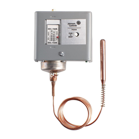
Fig. 1 -- A70 Temperature
Control with a style 1 sensing
element.
2A70, A72 Technical Bulletin
7. Take the following steps
when mounting a control
with a vapor-pressure
sensing element. (See
Fig. 9.)
a. Mount the control with
the power element
down.
b. Mount the control and
bulb at approximately
the same level.
c. Mount the bulb with the
free (sealed) end lower
than the capillary end.
Note: On cross
ambient models the
side of the bulb marked
“TOP” should always
be up.
!
CAUTION: Do not dent or
deform the sensitive bulb of
this control. A dent or
deformation will change the
calibration and cause the
control to cycle at a
temperature lower than the
dial setting. When a bulb
mounting clip is used to
mount the bulb near the
refrigerant tubing, be sure
the sheet metal screw does
not pierce the tubing.
Wiring
!
CAUTION: Disconnect the
power supply before the
wiring connections are
made to avoid possible
electrical shock or damage
to the equipment. On
multiple circuit units, more
than one circuit may have
to be disconnected.
Make all wiring connections
using copper conductors only,
and in accordance with the
National Electrical Code and
local regulations. For maximum
electrical rating of the control,
see the electrical rating shown
on the inside cover label of the
control.
The contacts on the single-pole
A70 controls with main and
auxiliary contacts are identified
on the contact block. The main
contacts are LINE-M2 and the
auxiliary contacts are LINE-M1.
The action of the main contacts
are shown on the cover label.
Figure 6 shows a typical wiring
hookup.
Where it is desirable for the user to
increase or decrease the DIFFERENTIAL
ONLY, external adjusting knob is supplied
on differential screw as shown in Fig. 4.
Knob is provided with stops and factory
assembled to permit change only within a
specified range.
External adjusting knob may be placed on range
screw, as shown in Fig. 5, where it is necessary
for the user to raise or lower both CUT-IN and
CUT-OUT points (differential remains constant).
Knob is provided with stops and factory
assembled to permit adjustments within a
specified range.
NOTE: Knob is usually factory assembled in
either position as shown in Figs. 4 or 5 above,
depending upon specifications of original buyer.
However, knob may be changed in the field
from the differential to the range screw or vice
versa by loosening set screw and removing
knob and indicator plate and reversing their
positions. Assuming that knob is factory
assembled on range screw (Fig. 5) and set to
restrict adjustment to 10F° (5.6C°), adjustment
will be restricted to approximately 5F°(2.8C°) if
knob is placed on differential screw
(Fig. 4).
MANUAL RESET
BUTTON
Manual button shown in
Fig. 3, left, when
supplied provides
MANUAL START only.
Button must be pushed
and released to restart
after lockout occurs.
Fig. 7 -- Interior view of “Open Low”
temperature control showing how to adjust
the set point and differential.
Fig. 8 -- Interior view of “Open High”
temperature control showing how to adjust
the set point and differential.
A70, A72 Technical Bulletin 3
!
CAUTION: Use No. 8-32 ×
1/4 in. terminal screws.
Longer screws can interfere
with the switch mechanism
and damage the switch.
Adjustment
The controls have a single
“sight-set” calibrated scale which
shows both the cut-in and cutout
settings. Adjustments can be
made without removing the
control cover. (See Figs. 7
and 8.)
If the control is equipped with
lockout, the contacts must be
reset manually after lockout
occurs. (See Fig. 3.)
Checkout Procedure
The operating point of the
control should be confirmed by
an accurate thermometer.
Before leaving the installation,
observe at least three complete
operating cycles to be sure that
all components are functioning
correctly. If the control setting is
outside the normal operating
range of the controlled device,
the operation of the control
should be simulated by
actuating the contacts to confirm
that the electrical connections
are correct.
Repairs and Replacement
Field repairs must not be made
except for replacement of the
cover and knob. For a
replacement control, cover or
knob, contact the nearest
Johnson Controls wholesaler.
4A70, A72 Technical Bulletin
Notes
www.penncontrols.com
® Johnson Controls and PENN are registered trademarks of Johnson Controls in the
United States of America and/or other countries. All other trademarks used herein are the property
of their respective owners. © Copyright 2019 by Johnson Controls. All rights reserved.

This manual suits for next models

6

Other Johnson Controls Temperature Controllers manuals
Johnson Controls TM-11x1 series User manual

Johnson Controls

Johnson Controls TM-11x1 series User manual

Johnson Controls A11D User manual

Johnson Controls

Johnson Controls A11D User manual

Johnson Controls TM-2161 User manual

Johnson Controls

Johnson Controls TM-2161 User manual

Johnson Controls TE-63xS Series User manual

Johnson Controls

Johnson Controls TE-63xS Series User manual

Johnson Controls System 350 A350A Service manual

Johnson Controls

Johnson Controls System 350 A350A Service manual

Johnson Controls MS4PMUHVT User manual

Johnson Controls

Johnson Controls MS4PMUHVT User manual

Johnson Controls FX-WRZ Series User manual

Johnson Controls

Johnson Controls FX-WRZ Series User manual

Johnson Controls T606MSP-4 User manual

Johnson Controls

Johnson Controls T606MSP-4 User manual

Johnson Controls TE-631xM User manual

Johnson Controls

Johnson Controls TE-631xM User manual

Johnson Controls A11A User manual

Johnson Controls

Johnson Controls A11A User manual

Johnson Controls A419 Series User manual

Johnson Controls

Johnson Controls A419 Series User manual

Johnson Controls System 350T A350P User manual

Johnson Controls

Johnson Controls System 350T A350P User manual

Johnson Controls TE-6800 Series User manual
Johnson Controls

Johnson Controls TE-6800 Series User manual

Johnson Controls TE-6800 Series User manual

Johnson Controls

Johnson Controls TE-6800 Series User manual

Johnson Controls TE730 Series User manual

Johnson Controls

Johnson Controls TE730 Series User manual

Johnson Controls A419ABG-3C User manual

Johnson Controls

Johnson Controls A419ABG-3C User manual

Johnson Controls W43A User manual

Johnson Controls

Johnson Controls W43A User manual

Johnson Controls WRZ-7860-0 User manual

Johnson Controls

Johnson Controls WRZ-7860-0 User manual

Johnson Controls A19D User manual

Johnson Controls

Johnson Controls A19D User manual
Johnson Controls A70 Series User manual

Johnson Controls

Johnson Controls A70 Series User manual

Johnson Controls A419 Series Manual

Johnson Controls

Johnson Controls A419 Series Manual

Johnson Controls MS2 Manual

Johnson Controls

Johnson Controls MS2 Manual
Popular Temperature Controllers manuals by other brands

montwill M1 user manual

montwill

montwill M1 user manual

oventrop Unibox E BV vario operating instructions

oventrop

oventrop Unibox E BV vario operating instructions

Ekinex EK-ET2-TP user manual

Ekinex

Ekinex EK-ET2-TP user manual

Pentair TEC24VCNTLR instruction manual

Pentair

Pentair TEC24VCNTLR instruction manual

MISUMI MTCTR manual

MISUMI

MISUMI MTCTR manual

Stafford Instruments ST325 User handbook

Stafford Instruments

Stafford Instruments ST325 User handbook

BriskHeat TB4000 instruction manual

BriskHeat

BriskHeat TB4000 instruction manual

Bticino MH04 Technical guide

Bticino

Bticino MH04 Technical guide

MECHELECTRIC DIGISTAT 3 quick start guide

MECHELECTRIC

MECHELECTRIC DIGISTAT 3 quick start guide

Omron EJ1 EtherCAT user manual

Omron

Omron EJ1 EtherCAT user manual

Auber SYL-1615 instruction manual

Auber

Auber SYL-1615 instruction manual

Gemo LT172 Installation

Gemo

Gemo LT172 Installation

TestEquity F4 user manual

TestEquity

TestEquity F4 user manual

Auber Instruments SYL-2372 instruction manual

Auber Instruments

Auber Instruments SYL-2372 instruction manual

Phidgets 1048 quick start guide

Phidgets

Phidgets 1048 quick start guide

Evinox ViewSmart user guide

Evinox

Evinox ViewSmart user guide

Dimplex RT 202 quick start guide

Dimplex

Dimplex RT 202 quick start guide

Panasonic KT7 instruction manual

Panasonic

Panasonic KT7 instruction manual

manuals.online logo
manuals.online logoBrands
  • About & Mission
  • Contact us
  • Privacy Policy
  • Terms and Conditions

Copyright 2025 Manuals.Online. All Rights Reserved.