manuals.online logo
Brands
  1. Home
  2. •
  3. Brands
  4. •
  5. Johnson Controls
  6. •
  7. Temperature Controllers
  8. •
  9. Johnson Controls A19D User manual

Johnson Controls A19D User manual

Installation Sheets Manual 121
Temperature Controls Section A
Technical Bulletin A19D
Issue Date 0988
© 1988 Johnson Controls, Inc. 1
Code No. LIT-121050
Form 997-360-5
A19D Series
Surface Mounted Temperature Control
Application
This control incorporates a single-
pole, double-throw contact
mechanism and is designed
especially for mounting on hot
water pipes.
As a high temperature cutout
control, the contacts which open on
a rise in temperature are used. As
a low temperature cutout control for
use on unit heaters, the contacts
which open on a falling temperature
are used.
Do not install where the case
temperature exceeds 140°F (60°C)
or the sensing element temperature
exceeds 290°F (143°C).
All Series A19 temperature controls
are designed for use only as
operating controls. Where an
operating control failure would
result in personal injury and/or loss
of property, it is the responsibility of
the installer to add devices (safety,
limit controls) or systems (alarm,
supervisory) that protect against, or
warn of, control failure.
Adjustment and Operation
Adjusting screw “B,” Fig. 3, permits
screwdriver adjustment of control
point between 100°F (38°C) and
240°F (116°C). The temperature
differential is factory set,
nonadjustable, and is
approximately 10F° (5.5C°)
depending on rate of temperature
change.
Convertible adjustment models can
be field converted from concealed
screwdriver slot adjustment to knob
adjustment or external screwdriver
slot adjustment. They are supplied
with a snap-in plug in the cover to
provide concealed screwdriver slot
adjustment. For knob adjustment
remove the snap-in plug and
assemble the knob to the slotted
shaft. For external screwdriver slot
adjustment remove the snap-in plug.
On boiler applications where the A19
is used as a high temperature cutout
control, follow the boiler
manufacturer’s recommendations for
temperature setting. The heating
plant should be operated until the
maximum temperature setting
recommended by the boiler
manufacturer is reached. If the
control has not operated by this
time, turn the adjusting screw back
just to the point where the system
shuts down.
When used as a low temperature
cutout control on a unit heater the
control should be set high enough to
prevent the discharge of cold air.
Unless otherwise specified, a setting
of 120°F (49°C) should be used as a
starting point. If fan fails to start with
steam or hot water supply on, the
setting is too high. The setting is too
low if the fan delivers cool air after
the steam or hot water has shut off.
Installation
Mounting
Boiler Application
!
CAUTION: Do not install this
control on riser pipe
containing a flow control
device. The flow control
device will prevent
circulation of hot water
unless circulator is
operating.
Install the control on the vertical
riser pipe from the boiler
approximately 2 feet (.6 m) above
the boiler opening.
Immersion type controls are
normally used for cutout control
application on forced hot water
heating systems.
Unit Heater Control
Mount the control on the
horizontal return line adjacent to
the unit heater. In this position
it will close the contacts when
hot condensate or hot water is
leaving the unit heater.
Other Applications
Control can be mounted in any
position on the pipe to sense
pipe temperature. The control is
not position sensitive.
1. If a pipe is insulated, remove
a 5 in. (127 mm) section of
insulation. Scrape pipe
surface clean, removing
insulating material, scale
and rust.
2. Remove the cover from the
control and fasten threaded
flange of the strap to the
control case using only 3 or 4
threads of mounting screw.
(See Fig. 7.) Place the control
Fig. 2 -- Controls with
convertible adjustment have
a snap-in plug in the cover
and a knob for field
installation.
Fig. 1 -- Surface Mounted
Temperature Control less
mounting strap.
2 A19D Technical Bulletin
on pipe, wrap strap around
pipe and place slot in strap
over tab on right side of case.
Tighten the strap screw to a
snug fit. Clip off or bend back
excess strap outside the cover
of the control.
3. Insulation attached to the rear
of control will minimize the
effect of ambient air
temperature on the set point of
control. If practical, replace a
portion of removed pipe
insulation for appearance.
Wiring
!
CAUTION: Disconnect
power supply before wiring
connections are made to
avoid possible electrical
shock or damage to
equipment.
All wiring should be made in
accordance with the national
Electrical Code and local codes.
The case is provided with a
7/8 in. (22 mm) diameter hole for
1/2 in. conduit to permit
installation of conduit where
required. The terminals of the
single-pole double-throw contact
unit are color coded with the red
terminal common; red to blue
circuit opens on temperature
rise, red to yellow circuit closes
on temperature rise. See typical
wiring diagrams in Figs. 4 and 5.
Use copper conductors only.
1. On high temperature cutout
control applications, always
wire the “hot” line to the A19D
cutout control in accordance
with Fig. 4.
2. On low cutout control
applications, follow equipment
manufacturer’s wiring
recommendations whenever
possible. Fig. 5 shows a
common wiring hookup for this
application.
!
CAUTION: Use terminal
screws furnished (8-32 x
1/4 in. binder head).
Substitution of other
screws may cause
problems in making proper
connections.
Temperature Cutout Stop
The temperature cutout stop is
an integral part of these controls
and can be field adjusted. To
set temperature cutout stop,
proceed as follows:
1. Set dial to temperature at
which stop is desired.
2. Remove control cover.
3. Loosen the cutout stop screw,
slide the screw to the front of
the control against the plastic
step behind the dial and
tighten the screw. (See Fig. 6.)
Sometimes an exact stop
setting is not possible and the
stop must be set to the closest
step corresponding to the dial
setting required.
Checkout Procedure
Before applying power, make sure
installation and wiring connections
are according to job specifications.
Before leaving the installation, at
least three complete operating
cycles should be observed to see
that all components are
functioning correctly.
Repairs and Replacement
Field repairs must not be made.
For replacement control, contact
the nearest Johnson Controls
wholesaler.
Fig. 3 -- Note color coded switch.
Mounting strap is held to control by
clamp screw. See Fig. 7 for mounting
instructions.
Controls Group
507 E. Michigan Street
P.O. Box 423
Milwaukee, WI 53201 Printed in U.S.A.

Other Johnson Controls Temperature Controllers manuals
Johnson Controls TM-2161 User manual

Johnson Controls

Johnson Controls TM-2161 User manual

Johnson Controls TE-6800 Series User manual

Johnson Controls

Johnson Controls TE-6800 Series User manual

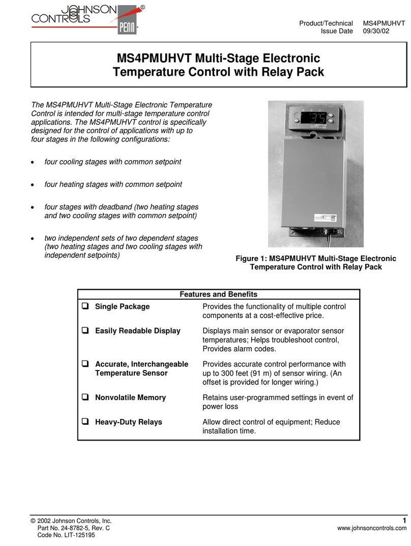
Johnson Controls MS4PMUHVT User manual

Johnson Controls

Johnson Controls MS4PMUHVT User manual

Johnson Controls PENN A70 Series User manual
Johnson Controls

Johnson Controls PENN A70 Series User manual

Johnson Controls A11A User manual

Johnson Controls

Johnson Controls A11A User manual

Johnson Controls A419ABG-3C User manual

Johnson Controls

Johnson Controls A419ABG-3C User manual

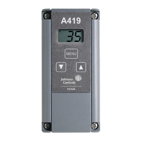
Johnson Controls A419 Series User manual

Johnson Controls

Johnson Controls A419 Series User manual

Johnson Controls TE-63xS Series User manual

Johnson Controls

Johnson Controls TE-63xS Series User manual

Johnson Controls T606MSP-4 User manual

Johnson Controls

Johnson Controls T606MSP-4 User manual

Johnson Controls A11D User manual

Johnson Controls

Johnson Controls A11D User manual

Johnson Controls MS2 Manual

Johnson Controls

Johnson Controls MS2 Manual
Johnson Controls System 350T A350P User manual

Johnson Controls

Johnson Controls System 350T A350P User manual

Johnson Controls FX-WRZ Series User manual

Johnson Controls

Johnson Controls FX-WRZ Series User manual

Johnson Controls TM-11x1 series User manual

Johnson Controls

Johnson Controls TM-11x1 series User manual

Johnson Controls A419 Series Manual

Johnson Controls

Johnson Controls A419 Series Manual

Johnson Controls TE-631xM User manual

Johnson Controls

Johnson Controls TE-631xM User manual

Johnson Controls A70 Series User manual

Johnson Controls

Johnson Controls A70 Series User manual

Johnson Controls TE-6800 Series User manual

Johnson Controls

Johnson Controls TE-6800 Series User manual

Johnson Controls System 350 A350A Service manual

Johnson Controls

Johnson Controls System 350 A350A Service manual

Johnson Controls TE730 Series User manual
Johnson Controls

Johnson Controls TE730 Series User manual

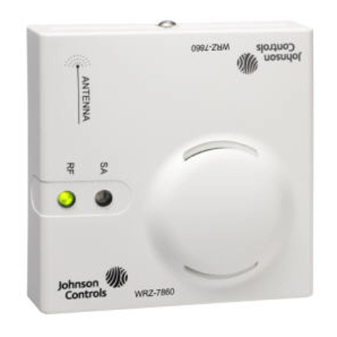
Johnson Controls WRZ-7860-0 User manual
Johnson Controls

Johnson Controls WRZ-7860-0 User manual

Johnson Controls W43A User manual

Johnson Controls

Johnson Controls W43A User manual

Popular Temperature Controllers manuals by other brands

Shimaden SR70 Series instruction manual

Shimaden

Shimaden SR70 Series instruction manual

Powtier Controls TC308 instruction manual

Powtier Controls

Powtier Controls TC308 instruction manual

Shinko ACS-13A Communication instruction manual

Shinko

Shinko ACS-13A Communication instruction manual

Gira KNX/EIB operating instructions

Gira

Gira KNX/EIB operating instructions

ABB TSP341-N Detailed installation instructions

ABB

ABB TSP341-N Detailed installation instructions

dixell XH360L operating instructions

dixell

dixell XH360L operating instructions

Lutron Electronics LR-TEMP-FLSH installation instructions

Lutron Electronics

Lutron Electronics LR-TEMP-FLSH installation instructions

Eurotherm 2116 user guide

Eurotherm

Eurotherm 2116 user guide

Auber Instruments SYL-1512A instruction manual

Auber Instruments

Auber Instruments SYL-1512A instruction manual

ILX Lightwave LDT-5412B user guide

ILX Lightwave

ILX Lightwave LDT-5412B user guide

Penn A421ABT series installation instructions

Penn

Penn A421ABT series installation instructions

Oregon Scientific THGN132N user manual

Oregon Scientific

Oregon Scientific THGN132N user manual

Rehau NEA SMART 2.0 Quick install

Rehau

Rehau NEA SMART 2.0 Quick install

Anly AT02 Series user manual

Anly

Anly AT02 Series user manual

RKC INSTRUMENT RZ100 instruction manual

RKC INSTRUMENT

RKC INSTRUMENT RZ100 instruction manual

aci BACnet Series Installation & operation instructions

aci

aci BACnet Series Installation & operation instructions

S+S Regeltechnik THERMASGARD RGTF1 Series Operating Instructions, Mounting & Installation

S+S Regeltechnik

S+S Regeltechnik THERMASGARD RGTF1 Series Operating Instructions, Mounting & Installation

Stahl 8146/5051 Series operating instructions

Stahl

Stahl 8146/5051 Series operating instructions

manuals.online logo
manuals.online logoBrands
  • About & Mission
  • Contact us
  • Privacy Policy
  • Terms and Conditions

Copyright 2025 Manuals.Online. All Rights Reserved.