manuals.online logo
Brands
  1. Home
  2. •
  3. Brands
  4. •
  5. Johnson Controls
  6. •
  7. Thermostat
  8. •
  9. Johnson Controls A19BAC User manual

Johnson Controls A19BAC User manual

Installation Sheets Manual 121
Temperature Controls Section
Technical Bulletin A19BAC, A28AA
Issue Date 0588
© 1988 Johnson Controls, Inc. 1
Code No. LIT-121077
A19BAC, A28AA Single and Two-Stage Space Thermostats
For Farm and General Purpose Applications
Application
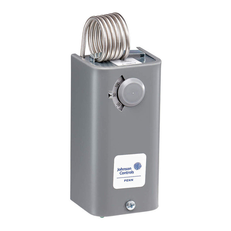
The single-stage A19BAC and
the two-stage A28AA
thermostats incorporate single-
pole double-throw switches for
controlling automatic ventilation
or heating in livestock barns,
poultry houses, milk houses,
brooder houses and other
buildings. The 30 to 110°F (0 to
43°C) and 0 to 140°F (-15 to
60°C) temperature ranges
permit use for many space
applications.
All Series A19 and A28 space
thermostats are designed for
use only as operating
controls. Where an operating
control failure would result in
personal injury and/or loss of
property, it is the
responsibility of the installer
to add devices (safety, limit
controls) or systems (alarm,
supervisory systems) that
protect against, or warn of,
control failure.
Operation
On a temperature increase to
the dial setting, the circuit
between R and Y closes.
Simultaneously the R and B
circuit opens.
Figure 3 illustrates the operation
of the A28AA. On a temperature
increase to the dial setting, the
circuit between R and Y of the
low stage switch (RYL) closes.
Simultaneously the circuit
between R and B (RBL) opens.
On a further increase in
temperature the high stage
switch operates and closes RYH
while simultaneously opening
RBH. The reverse sequencing
takes place on a temperature
fall.
Installation
Mounting
Mounting may be by wiring
conduit or to a flat surface with
screws through holes provided
in back of frame.
!
CAUTION: On rough
mounting surfaces use the
top two mounting holes
only. When these controls
are mounted on an uneven
surface using screws in all
four holes, the case can be
twisted enough to affect
the thermostat’s calibration
and operation.
Mount the thermostat 5 to 6 feet
above the floor where it will be
exposed to the average
temperature of the controlled
space. Do not mount where it
will be affected by unusual heat
or cold, such as directly over an
animal stall or in sunlight. Avoid
locations near a door, window or
hay chute. Do not mount on an
outside wall or where maximum
ambient temperature exceeds
140°F (60°C).
!
CAUTION: Do not dent or
deform the sensitive bulb
of this thermostat. A dent
or deformation will change
the calibration and cause
the thermostat to cycle at a
temperature lower than the
dial setting.
Adjustment
Knob adjustment or screwdriver
slot is supplied on the range
screw. Dial pointer is located on
cutout stop bracket on knob and
screwdriver adjustment models.
Solid cover models are adjusted
by removing cover and moving
dial so set point is in line with
dial pointer on the stop bracket.
(See Fig. 4.)
Fig. 1 -- Exterior view of Space
Thermostat.
Convertible adjustment models
can be field converted from
concealed screwdriver slot
adjustment to knob adjustment
or external screwdriver slot
adjustment. They are supplied
with a snap-in plug in the cover
to provide concealed
screwdriver slot adjustment. For
knob adjustment remove the
snap-in plug and press the knob
onto the slotted shaft. For
external screwdriver slot
adjustment remove the snap-in
plug.
The A28AA switch is stamped to
indicate the HI-TEMP switch and
the LO-TEMP switch.
A high temperature cutout stop
is supplied on the thermostats.
(See Fig. 4.) If cutout stop is
required proceed as follows:
1. Set dial to temperature at
which stop is desired.
Fig. 2 -- The Space Thermostats
with convertible adjustment
have a snap-in plug in the
cover, built-in screwdriver slot
and a knob for field installation.
2 A19BAC, A28AA Technical Bulletin
2. Remove cover from
thermostat.
3. Loosen the cutout stop
screw, slide the screw to the
front of the thermostat
against the plastic stop
behind the dial and tighten
the screw. (See Fig. 4.)
Sometimes an exact stop
setting is not possible and
stop must be set to the
closest step corresponding
to dial setting required.
4. Turn dial to set point
desired.
5. Replace cover.
Wiring
!
CAUTION: Disconnect
power supply before wiring
connections are made to
avoid electrical shock or
possible damage to
equipment.
All wiring should conform to local
codes and the National
Electrical Code. Use copper
conductors only. Do not use on
applications where electrical
ratings exceed ratings shown on
the thermostat’s cover label.
See Figs. 5 through 11 for
typical wiring applications.
!
CAUTION: Use terminal
screws furnished
(8-32 ×1/4 in. binder
head). Substitution of
other screws may cause
problems in making proper
connections.
Checkout Procedure
Before leaving the installation,
observe at least three complete
operating cycles to be sure that
all components are functioning
correctly.
Check for correct operation in
the following manner.
1. A19BAC -- Ventilating or
Cooling System: Turn dial
clockwise to a setting above
space temperature. Fan or
cooling system should be
off. When dial is turned
counterclockwise, the fan or
cooling system should turn
on approximately at the dial
setting.
A19BAC -- Heating System:
Turn dial clockwise above
the space temperature; the
heating unit should be on.
When dial is turned
counterclockwise, the
heating unit should turn off
approximately at the dial
setting.
2. A28AA -- If hookup is similar to
Fig. 8, fan should start at
approximately space
temperature and should
change to high speed as the
dial is turned counterclockwise
to a lower temperature setting.
If wiring is similar to Fig. 9, the
damper should open as the
dial is turned counterclockwise.
The devices should act in
reverse sequence when the
dial is turned clockwise to a
higher setting.
3. If control devices do not
operate in the manner
described above, check all
wiring for short circuits and
tightness of wiring
connections. If controlled
devices operate in reverse
(start in high or fully open
position) check wiring as it is
probably reversed.
Repairs and Replacement
Field repairs must not be made.
For replacement thermostat
contact the nearest Johnson
Controls wholesaler.
A19BAC, A28AA Technical Bulletin 3
4 A19BAC, A28AA Technical Bulletin
Notes
Controls Group
507 E. Michigan Street
P.O. Box 423 Printed in U.S.A.
Milwaukee, WI 53202

This manual suits for next models

1

Other Johnson Controls Thermostat manuals

Johnson Controls T600HCN-1 User manual

Johnson Controls

Johnson Controls T600HCN-1 User manual

Johnson Controls T500HCP-1 User manual

Johnson Controls

Johnson Controls T500HCP-1 User manual

Johnson Controls T600MEP-2 User manual

Johnson Controls

Johnson Controls T600MEP-2 User manual

Johnson Controls T2000 series User manual

Johnson Controls

Johnson Controls T2000 series User manual

Johnson Controls ACC-WIFI User manual

Johnson Controls

Johnson Controls ACC-WIFI User manual

Johnson Controls T-901 User manual

Johnson Controls

Johnson Controls T-901 User manual

Johnson Controls Hx3 S1-THXU430W Guide

Johnson Controls

Johnson Controls Hx3 S1-THXU430W Guide

Johnson Controls TEC2216-4 User manual

Johnson Controls

Johnson Controls TEC2216-4 User manual

Johnson Controls T8800 Series User manual

Johnson Controls

Johnson Controls T8800 Series User manual

Johnson Controls T6634-TE21 User manual

Johnson Controls

Johnson Controls T6634-TE21 User manual

Johnson Controls TVI-TD-6007 Series User manual

Johnson Controls

Johnson Controls TVI-TD-6007 Series User manual

Johnson Controls T9580 Operating instructions

Johnson Controls

Johnson Controls T9580 Operating instructions

Johnson Controls TEC2201-2 User manual

Johnson Controls

Johnson Controls TEC2201-2 User manual

Johnson Controls TEC2045-2 User manual

Johnson Controls

Johnson Controls TEC2045-2 User manual

Johnson Controls T-4002 Use and maintenance manual

Johnson Controls

Johnson Controls T-4002 Use and maintenance manual

Johnson Controls Hx 3 S1-THXU430W User manual

Johnson Controls

Johnson Controls Hx 3 S1-THXU430W User manual

Johnson Controls T600HCN-3 User manual

Johnson Controls

Johnson Controls T600HCN-3 User manual

Johnson Controls York DPC-1 Manual

Johnson Controls

Johnson Controls York DPC-1 Manual

Johnson Controls NXT-INT-01 User manual

Johnson Controls

Johnson Controls NXT-INT-01 User manual

Johnson Controls TEC2101-3 N2 User manual

Johnson Controls

Johnson Controls TEC2101-3 N2 User manual

Johnson Controls T701DFP-4 User manual

Johnson Controls

Johnson Controls T701DFP-4 User manual

Johnson Controls T701DFP-1 User manual

Johnson Controls

Johnson Controls T701DFP-1 User manual

Johnson Controls TEC2604-4 User manual

Johnson Controls

Johnson Controls TEC2604-4 User manual

Johnson Controls T60xDFH-4 User manual

Johnson Controls

Johnson Controls T60xDFH-4 User manual

Popular Thermostat manuals by other brands

Vive Comfort TP-S-955CR installation manual

Vive Comfort

Vive Comfort TP-S-955CR installation manual

Lux Products LUXPRO PSDH121B-010 Installation and operating instructions

Lux Products

Lux Products LUXPRO PSDH121B-010 Installation and operating instructions

EPH T47-RFi operating instructions

EPH

EPH T47-RFi operating instructions

White Rodgers 1F90-51 Operation guide

White Rodgers

White Rodgers 1F90-51 Operation guide

Cosmo CFTN manual

Cosmo

Cosmo CFTN manual

hager WH104404 User instructions

hager

hager WH104404 User instructions

VDH ALFANET 71 user manual

VDH

VDH ALFANET 71 user manual

Carrier Performance EDGE owner's manual

Carrier

Carrier Performance EDGE owner's manual

dixell SE10-45-P user manual

dixell

dixell SE10-45-P user manual

Honeywell Y9420H Sundial RF2 user guide

Honeywell

Honeywell Y9420H Sundial RF2 user guide

Pego Expert nano 200NANO4CK13 quick start guide

Pego

Pego Expert nano 200NANO4CK13 quick start guide

Horstmann HCT 2 quick guide

Horstmann

Horstmann HCT 2 quick guide

Vimar 2950 instruction manual

Vimar

Vimar 2950 instruction manual

GE RAK180W1 Owner's Manual & Installation Instructions

GE

GE RAK180W1 Owner's Manual & Installation Instructions

Honeywell TR80 Mounting instructions

Honeywell

Honeywell TR80 Mounting instructions

JUMO KMf-20 operating instructions

JUMO

JUMO KMf-20 operating instructions

Amana 2246008 Installation, operation & application guide

Amana

Amana 2246008 Installation, operation & application guide

Danfoss TP4000 Range installation instructions

Danfoss

Danfoss TP4000 Range installation instructions

manuals.online logo
manuals.online logoBrands
  • About & Mission
  • Contact us
  • Privacy Policy
  • Terms and Conditions

Copyright 2025 Manuals.Online. All Rights Reserved.