JohnsonFit Matrix Retail A30 User manual

1
JOHNSON
Issue date 2017-2-20 Edition 01 Doc No. SM-TM-AF-009
Revision
date Edition time 01 Page 35
Approval Review Editor
Kyle.Schweitzer Alex Tang Dora Feng
A30/A50
Service manual

2
Matrix Retail A30 Matrix Retail A50
A30 A50
Frame
Resistance System Internal ECB Induction Brake
Handle Bar Type Stationary
DA Arm - foam wrapped
Stationary
DA Arm
Power Supply Yes (9 ft / 2.75m) Yes (8 ft / 2.44m)

3
Contents
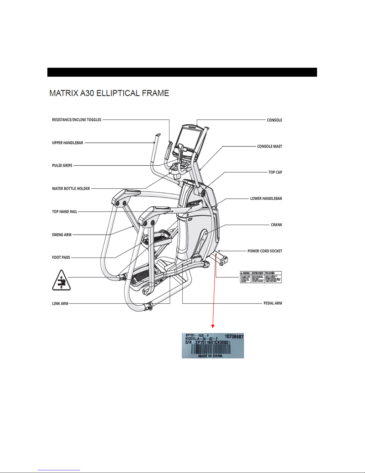
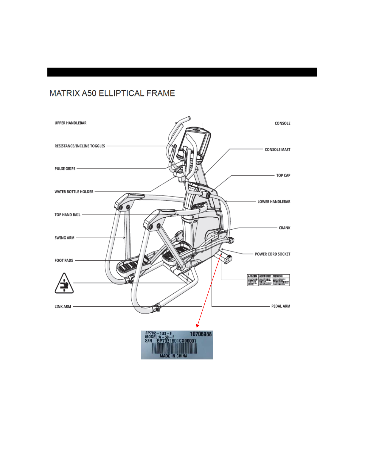
CHAPTER 1: SERIAL NUMBER LOCATION...................................................................................................5
CHAPTER 2: CONSOLE BROWSE..................................................................................................................8
CHAPTER 3: TROUBLESHOOTING
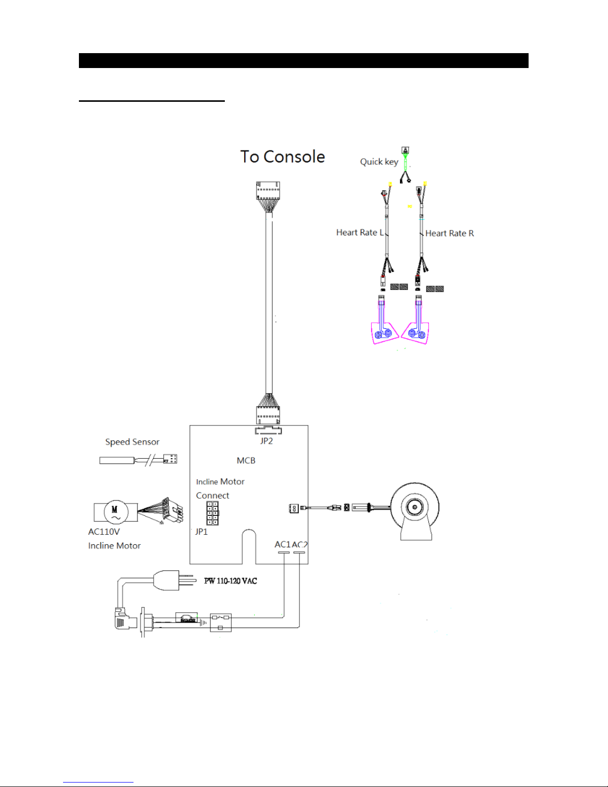
3.1 Electrical Diagram..................................................................................................................................9
3.2 MCB Connections................................................................................................................................12
3.3 Trouble Shooting..................................................................................................................................14
3.3.1 Console Does Not Light Up.....................................................................................................14
3.3.2 No Console Response.............................................................................................................15
3.3.3 System Will Not Boot...............................................................................................................15
3.3.4 No Display on the Console or the Display is Dim....................................................................15
3.3.5 No RMP Display.......................................................................................................................16
3.3.6 No Resistance Or Incorrect Resistance...................................................................................17
3.3.7 Heart Rate Function Issues.....................................................................................................20
3.3.8 Pedals Slipping........................................................................................................................21
3.3.9 Knocking and Creaking Noise..................................................................................................22
3.3.10 Handlebar Keypad Failure........................................................................................................23
CHAPTER 4: PART REPLACEMENT GUIDE
4.1 Console Replacement .......................................................................................................................... 24
4.2 Heart Rate Grip Replacement .............................................................................................................. 25
4.3 Upper Handle Bar Replacement .......................................................................................................... 26
4.4 Lower Handle Bar Replacement .......................................................................................................... 27
4.5 Pedal Arm Replacement ...................................................................................................................... 28
4.6 Console Mast Covers Replacement………………………………………………………………………...29
4.7 Console Mast Replacement ................................................................................................................. 30
4.8 Link Arm Replacement ......................................................................................................................... 31
4.9 Crank Arm Replacement ...................................................................................................................... 32

4
4.10 Front Cover Replacement .................................................................................................................. 33
4.11 Side Cover Replacement ................................................................................................................... 34
4.12 LCB&ECB Motor Replacement .......................................................................................................... 35
4.13 Elevation Motor Replacement ............................................................................................................ 36
4.14 Drive Axle Replacement………………………………………………………………………………………37
4.15 Generator Replacement………………………………………………………………………………………38

5
CHAPTER 1: Serial Number Location

6
CHAPTER 1: Serial Number Location

7
CHAPTER 1: Serial Number Location

8
CHAPTER 2: Console Browse
Please refer to XR/XER/XIR service manual to get more details.

9
CHAPTER 3: Troubleshooting
3.1 ELECTRICAL DIAGRAM
A30

10
CHAPTER 3: Troubleshooting
3.1 ELECTRICAL DIAGRAM
A50

11
CHAPTER 3: Troubleshooting
3.1 ELECTRICAL DIAGRAM
A30/50 Connection
Console Connection

12
CHAPTER 3: Troubleshooting
3.2 MCB Connections
A30 MCB
1 AC input connector
2 Incline connector
3 ECB connector
4 Console connector

13
CHAPTER 3: Troubleshooting
3.2 MCB Connections
A50 MCB
CN1 Incline Motor Connector
CN2 Console Connector
CN3 RPM feedback wire connector

14
CHAPTER 3: Troubleshooting
3.3.1 TROUBLESHOOTING – CONSOLE DOES NOT LIGHT UP
Symptom: No power to the console.
Solution:
1. Check the connection of the console cable at the console. Unplug the console cable from console, and
use a multi-meter to check the voltage through the console cable. Normally it should be 12VDC
between pin1 & pin8. If no voltage is present, the console cable or LCB is defective. Test voltage at
LCB, if voltage is present replace console. If not, replace LCB.
2. If the voltage through the console cable is 12VDC, the console is defective. Replace it.
FIGURE A
(Console cable’s connectors with UCB)

15
CHAPTER 3: Troubleshooting
3.3.2 TROUBLESHOOTING- No Console Response
Symptom: The power is on, the console lights up, and a program can be started, but there is no control
over the program.
Solution:
Enter into Engineering Mode and make sure that the Machine Type is set correctly.
3.3.3 TROUBLESHOOTING- System Will Not Boot
Symptom: System Will Not Boot
The LCD has a back light, but the system does not boot up (does not display the Matrix logo)
Solution:
1. Reload the software into UCB. Test the UCB. If fail, the system crashed, replace the UCB.
3.3.4 TROUBLESHOOTING- No Display on the Console or the Display is Dim
Symptom: No Display on the Console or the Display is Dim
Solution:
1. Check the connection of the console cable at the UCB.
2. Remove the console cable from the J5 socket on the console. Pedal the machine. Set your multi-meter to
DC voltage. Place both terminals on pins 1 & 4 of the console cable. There should be a reading of more
than 5.5VDC .If voltage is more than 5.5VDC, replace the console. If voltage is less than 5.5VDC, or the
new console does not resolve the issue, replace the console cable.
3. Open the shrouds then check if all the wire harnesses are connected properly to the terminals of the LCB.
4. A50.
Unplug the generator cable from the control board, set your multi-meter to OHMS place both terminals on
pins 1 &2, pins 2 & 3, and pins 3 & 1 of the generator terminal to check if the OHMS are all equal. If the
OHM reading shown same on all 3 phases, replace the LCB. If the OHMS reading shown is not same,
replace the generator.

16
CHAPTER 3: Troubleshooting
3.3.5 TROUBLESHOOTING – No RPM Display
Symptom: No RPM shown on the console.
Solution:
1. Bad connection between the console cable and the console: re-connect the console wire.
2. Speed sensor wire defective: Check the gap between the speed sensor and magnet on pulley. It is normal
within 5mm (Fig A).Adjust the gap if it is too large. Test sensor with Ohm meter with pin1 and pin2,pass
magnet by sensor to test.
3. Lost magnet of pulley: Re-install a new magnet (Fig. B).
4. Console defective: Replace the console set.

17
CHAPTER 3: Troubleshooting
3.3.6 TROUBLESHOOTING – NO RESISTANCE OR INCORRECT RESISTANCE
Symptom:
1. The resistance cannot be adjusted during exercise.
2. The resistance is reverse or much too heavy.
Solution (For A30):
1. Turn on the console and check the ECB motor.
In resistance level 1, the head of steel rope directs to top right side (around 45 degree).
If the head of steel rope points to bottom left side, the resistance will be reverse. Adjust the head of steel
rope to the correct position.
Notes: in the highest resistance level, the cable should have no tension (see ECB motor replacement
section).
2. Press key “+” or “↑”to adjust the resistance.
A) If ECB motor cannot move, the resistance will not be changed. The ECB motor or console cable is
defective. Check the console cable inserted in ECB motor. Re-connect the console cable first, if still not
working, test cable for damage. If tests good, replace the ECB motor, make sure both cable ends are
seated properly.

18
CHAPTER 3: Troubleshooting
3.3.6 TROUBLESHOOTING – No Resistance Or Incorrect Resistance
B) If the ECB motor can move, the resistance can be adjusted. If the resistance is still too heavy, check
the gap between orange block and the bottom. It should be within 1-2 mm.
If the gap is larger than 1-2 mm, the resistance will be heavier than normal. Adjust the cable to the correct
gap range.
3. If all above conditions are ok, and the resistance is still too heavy, inside magnet is defective. Replace the
ECB flywheel.

19
CHAPTER 3: Troubleshooting
Solution (For A50):
1. Check the power resistor wire connection between the power resistor and LCB (fig-1)
2. Check the Connection wire between consoles to LCB. Try to plug off and plug on connector
(Page 13 ,CN2 )
3. Check the power resistor whether 10KΩ by multi-meter (Fig-2), if not, replace power resistor.
4. If yes, Replace. LCB.
Fig1 Fig2

20
3.3.7 TROUBLESHOOTING-Heart Rate Function Issues
Symptom: Heart Rate Function Does Not Work or is Reading Incorrectly
Solution:
1. The heart rate grips are not connected properly or are defective.
With a multi-meter set for DC voltage, place one terminal on each of the HR grip plates. The HR grip
should give a voltage reading of between 0.5 and 2.0VDC. If the voltage is not between 0.5 and 2.0VDC,
remove the 3 screws holding the HR grip together and check the connection of the HR grip wiring.
2. The heart rate grip wiring is damaged or not connected correctly.
Check continuity of the HR grip wiring.
Place one terminal of a multi-meter set for resistance on the HR grip wiring at the HR grip, and the other
terminal on the HR grip wiring at the console. An ohm reading of around 1 should be expected. If the
reading is higher than 1,replace the HR grip wiring. Also test continuity of one terminal and to the frame
(ground) to test for a pinched wire.
3. The HR board is damaged
Remove the console. Remove the 6 screws holding the front of the console to the rear. Check the
connection of the HR board wiring to the UCB. If all the wiring is intact and has good contact, replace the
HR board.
4. The UCB is damaged.
If the HR board, HR grips, and HR grip wiring do not solve the issue, replace the UCB.
This manual suits for next models
1
Table of contents
Popular Fitness Equipment manuals by other brands

GREEN SERIES FITNESS
GREEN SERIES FITNESS CIR-EL7000E-G1 owner's manual

Weider
Weider WEBE4496.0 user manual

Pro-Form
Pro-Form 510 EX user manual

Body Craft
Body Craft BC-F432 operating instructions

Star Trac
Star Trac Inspiration Strenght IP-S5308 installation instructions

Domyos
Domyos VE 570 operating instructions