Joinwit ZW3327 User manual

ZW3327
IL&RL T est Station
User M anual(V200806)
2020.08

Content
1Overview .......................................................................................................... 1
1.1 Product Overview .........................................................................................................1
1.2 Product Feature .............................................................................................................1
2 Technical specification .................................................................................... 2
3 Standard coniguration...................................................................................... 3
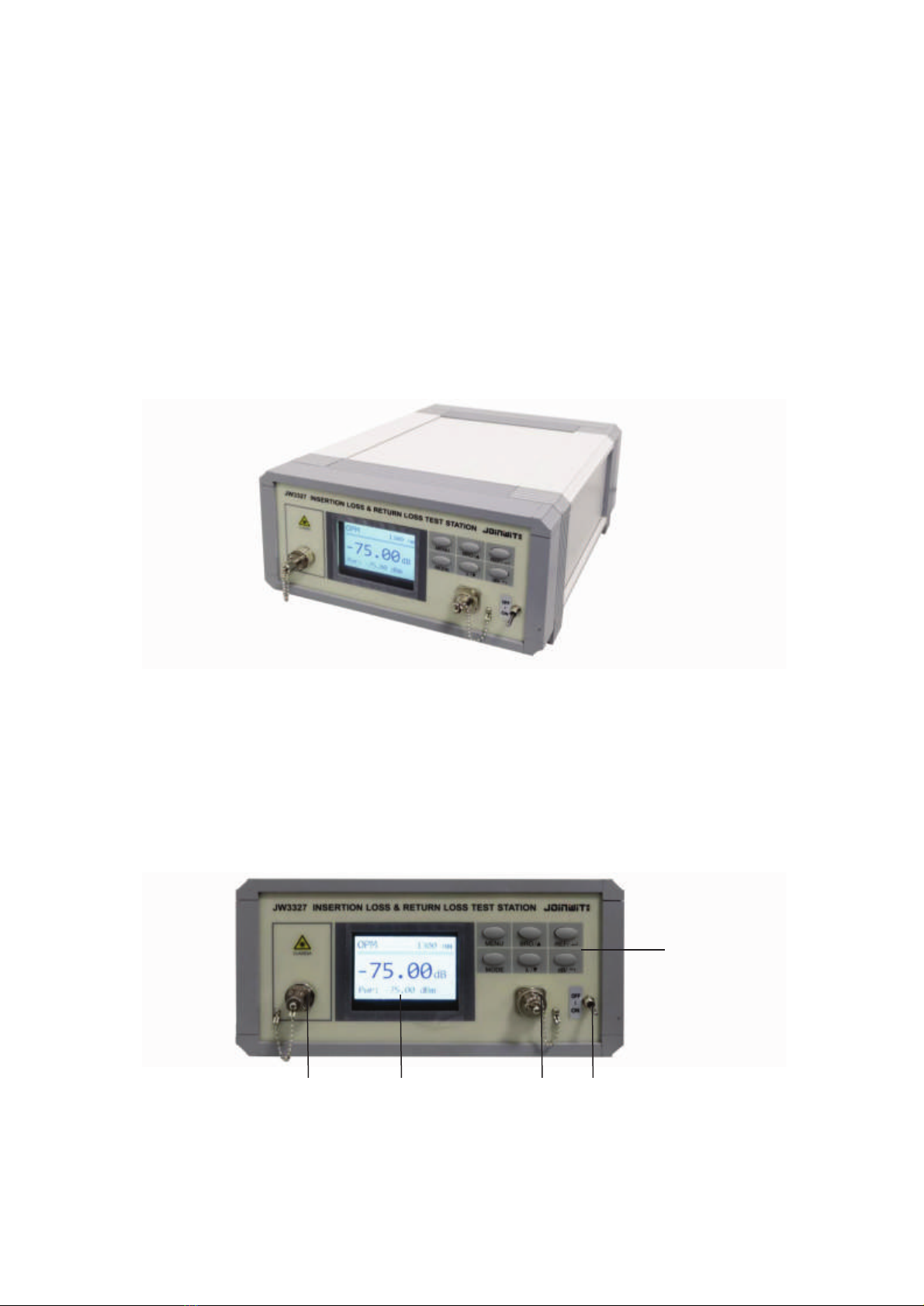
4 Overall Appearance ......................................................................................... 4
4.1 Overall Appearance ....................................................................................................4
4.2 Front Panel Appearance .............................................................................................4
4.3 Back Panel Appearance ..............................................................................................5
5 Button Instrauction .......................................................................................... 5
6 Menu Description ............................................................................................ 6
6.1 Menu Function Description ...........................................................................................6
6.2 Menu Setting Description ..............................................................................................7
6.3 Menu Setting Method ....................................................................................................8
6.3.1 Unit Seng.............................................................................................................8
6.3.2 Refresh Rate Seng ...............................................................................................8
6.3.3 Backlight Seng .....................................................................................................9
6.3.4 Threshold Seng ....................................................................................................9
6.3.5 Device Informaon Seng ...................................................................................10
6.3.6 Alarm Mode Seng ..............................................................................................11
7 User Instruction ............................................................................................. 11
7.1 Power On .................................................................................................................... 11
7.2 IL Value Test .............................................................................................................. 12
7.2.1 IL to Zero ..............................................................................................................11
7.2.2 IL test ....................................................................................................................12
7.3 RL Test ....................................................................................................................... 13
7.3.1 RL Calibraon .......................................................................................................13
7.3.2 RL Test ..................................................................................................................14
7.4 OPM Measurement ..................................................................................................... 16
7.5 VFL Control ............................................................................................................. 17

8 Test Software ................................................................................................ 17
8.1 Connecting Introduction .............................................................................................. 18
8.2 Setting option Introduction .......................................................................................... 18
8.3 Product information area introduction ......................................................................... 19
8.4 Data upload area introduction ...................................................................................... 19
8.5 Real-time data area introduction .................................................................................. 20
8.6 Test data area introduction .......................................................................................... 20
8.7 Data analysis area introduction .................................................................................... 21
8.8 Clear Data option introduction .................................................................................... 21
8.9 Database view option introduction .............................................................................. 21
9 Maintenance .................................................................................................. 23
10 Guarantee .................................................................................................... 24
Appendix1 .......................................................... Error! Bookmark not defined.
Appendix2 .......................................................... Error! Bookmark not defined.

1
1 Overview
1.1 Product Overview
ZW-3327 IL&RL Test Station is a combination of years production and testing
experience of its own optical passive components and optical communication
instrumentation, fully drawing on the advantages of instrumentation at home and
abroad, elaborate development of a precision optical detection instrument. It is widely
used in insertion loss and return loss testing for fiber optic cables, Passive optical
device and Fiber-optic communication systems, it is the basic test instrument for
manufacturers, scientific research institutions and operators for production testing,
research and development, and Engineering Construction and maintenance.
1.2 Features
1) Built-in High Stability Optical Light Source;
2) Multi-test mode, support dual-wavelength IL RL simultaneous test;
3) The upper computer and lower computer threshold can be set;
4) Support Multiple Fiber interface conversion;
5) Large color screen display
6) Support Multiple Communication Interfaces;
7) The insertion loss of multimode patch cord can be detected by adding 850
wavelength
8) Light Path built-in VFL, easy to find the other end of the patch cord, enhance the
test speed;

2
2 Technical specification
model ZW3327A ZW3327B
Optical return loss test SM MM
Test wavelength
(nm)
1310/1550(±10nm) 850/1300(±10nm)
Fiber type(um) 9/125 50/125 or 62.5/125
Output power(dBm) ≥-5 ≥-10
Output stability(dB) ±0.015(15min@25℃) ±0.05(15min@25℃)
Connector type FC/APC
Test range(dB) 0~75
Display resolution 0.1
Detector type InGaAs 2.0
Wavelength range
(nm)
800~1700
Calibration wavelength
(nm)
850/1300/1310/1490/1550/1625
Measurement range
(dBm)
+3~-75 +3~-70
Uncertainty of insertion
loss
±0.05dB ±0.1dB
Insertion loss stability ±0.01dB ±0.03dB
Power uncertainty
(dB)
0.25dB(+3~-55dBm)
Display resolution 0.01
Connector type Variety interface , FC/SC/ST/ universal Φ2.5mm/ universal
Φ1.25mm etc.

3
Display 3.5inch TFT color screen
Communication
interface
USB2.0/RS232/ Wireless module (optional)
operating system Win7 32/64 bit Win10 32/64 bit
display Recommend 21-inch display, Min resolution 1600*900
Operating temperature -5~+40℃
Storage temperature -25~+70℃
Power Supply AC 220V
Dimension(mm) 280x260x120
3 Standard Configuration
General product configurations are listed in the following table:
1 ZW-3327 main tester 1pc
2 Power Cord 1pc
3 Adapter(FC\SC\ST2.5mm、1.25mm) 1pack
4 FC/APC-FC/PC standard fiber(SM/MM) 1pc
5 FC/APC-FC/APC standard fiber(SM/MM) 1pc
6 User Manual 1pc
7 Cotton swabs 1pack
8 Fuse 1pc
9 CD(optional) 1pc
10 USB cable(optional) 1pc
11 RS232 serial port line(optional) 1pc
12 Wireless module(optional) 1pc
13 Foot pedal 2pcs

4
4 Overall Appearance
4.1 Overall Appearance
ZW-3327 IL&RL test station adopts high-grade aluminum profile case with clean
surface and atmosphere. The front panel uses TFT color screen as the display, font
display clear, no overlap. Full consideration of Ergonomics and take into account the
beauty, generous, machine appearance as shown in figure 4-1.
Figure 4-1 Overall appearance
4.2 Front Panel Appearance
The front panel of ZW3327 IL&RL test station includes light source outlet, display
area, light detector, VFL control switch and key press area, as shown in figure 4-2.
1 2 3 4
5

5
1 OLS output port 2 Display area 3 Detector port 4 VFL control switch 5
Button area
Figure 4-2 front panel appearance
4.3 Back panel appearance
The back panel of ZW3327 IL&RL test station contains data transfer pedal interface,
red light control pedal interface, USB interface, power interface and power switch, as
shown in figure 4-3.
1 Data transmission foot pedal interface 2 VFL controlled foot pedal interface 3
USB interface
4 Power interface 5 Power switch
Figure 4-3 Back panel appearance
5 Button Instruction
NO. Button
name
function
1 MENU 1:Enter Menu Settings
2:Move the button to the left (under threshold
setting)
2 BR0/▲ 1:RL Calibration(long press,under Single
1 2 3 4 5
AC 220V

6
RL measurement of interface)
2:Up(under menu)
3:Plus 1(under threshold setting)
3 REF/ 1:Set reference value(under single IL and RL
measurement interface)
2:Confirm and save(under menu)
4 MODE 1:Test mode switch(five modes)
a. Single wavelength IL measurement
b. Single wavelength RL measurement
c. Single wavelength IL&RL measure
simultaneously
d. Dual wavelength IL&RL measure
simultaneously
e. OPM
2:Move to the right (with the threshold set)
5 λ/▼ 1:Switching wavelength
2:Select down(under menu)
3:Minus 1(under threshold setting)
6 dB/ 1:Return to zero (Under single IL
measurement & OPM)
2:Return upper level menu not saved(under
menu)
Note: Short press if not specified as long press.
6 Menu Description
6.1 M enu function description
Press the MENU key to enter the main menu setting interface, as shown in Figure 6-1.

7
Figure 6-1 Main menu interface
Menu settings can be selected by pressing the up and down buttons of the keys. when
selected the font color will become red; By pressing the REF / Button of the key
to enter the selected submenu, then select the submenu options by the up and down
keys and REF / key, press DB / key in the Submenu to return to the main
Menu; press DB / key again in the main menu to exit the menu settings.
6.2 M enu setting description
No. Button
name
Function
1 Unit set 1:dBm
2:Watt
2 Refresh rate 1:100ms
2:200ms
3:400ms
4:1000ms
3 Backlight
set
1:100%
2:80%
3:60%
4:40%
5:20%
4 Threshold
set
1:1310 IL threshold
2:1310 RL threshold
3:1550 IL threshold
4:1550 RL threshold
M ENU
1: unit set
2: refresh rate
3: backlight set
4: Threshold Set
5: device info
6: alarm mode

8
5 Device info 1:ID
2:IL Send
3:RL Send
6 Alarm mode 1:non-alarm
2:fail alarm
3:pass alarm
6.3 M enu setting method
6.3.1 unit set
Press the MENU key to enter the MENU and select the unit settings; if the DBM unit
is selected, the power value on the main interface is displayed as a logarithmic value;
if the Watt unit is selected, the power value on the main interface is displayed as a
linear value, with the default unit being dBm, as shown in figure 6-2.
Figure 6-2 Unit set
6.3.2 Refresh rate setting
This menu sets the display refresh rate by default to 200ms, as shown in figure 6 -3.
1 Menu setting
1: dBm
2: Watt
2 Refresh rate
1: 100ms
2: 200ms
3: 400ms
4: 1000ms

9
Figure 6-3 Refresh rate setting
6.3.3 Backlight Setting
This menu adjusts the brightness of the display, as shown in figure 6-4. The default is
100% .
Figure 6-4 Backlight Setting
6.3.4 Threshold Setting
The menu includes threshold settings for insertion loss and return loss at 1310 and
1550 nm wavelengths, respectively. The resolution of insertion loss threshold is 0.01
and that of return loss threshold is 0.1. When the measured insertion loss is greater
than or equal to the range of insertion loss thresholds set, or the measured return loss
is less than or equal to the range of insertion loss thresholds set, the data will be
displayed in red font, as shown in figure 6-5. (This device threshold is completely
independent of the threshold set by the PC software)
3 Backlight Setting
1: 100%
2: 80%
3: 60%
4: 40%
5: 20%

10
Figure 6-5 Threshold Setting
6.3.5 Device Information Setting
ID: Local Address ID, used with the host computer software, multi-device networking
online use.
IL Send: Measured Insert Loss Upload Switch, with ON and OFF state. Status ON
indicates that the measured value is within the upper computer software threshold
range, triggered by a foot switch can upload data to the upper computer software;
status OFF indicates no upload.
4: Threshold Setting
1: 1310 IL threshold
2: 1310 RL threshold
3: 1550 IL threshold
4: 1550 RL threshold
1: 1310 IL threshold
0.2
2: 1310 RL threshold
65.0

11
RL Send: Return Loss Upload Switch, defined similar to IL Send.
Figure 6-6 Device information setting
6.3.6 Alarm Mode Setting
The menu can choose not alarm, unqualified alarm and qualified alarm mode, as
figure 6-7.
Figure 6-7 Alarm mode setting
7 User Instructions
7.1 Power on
Switch on 220V AC, open the power switch on the back panel, the screen will show
the boot interface.
7.2 Test IL Value
7.2.1 IL to Zero
During the test, the MODE key is used to switch to the single insertion loss
measurement MODE, the output end of the light source is connected to a calibrated
optical fiber matching connector as shown in figure 7 -1, calibration of the power
5: Device Info
ID: 30
IL Send: ON
RL Send: OFF
6: Alarm Mode
1: Non-alarm
2: FAIL alarm
3: PASS alarm

12
meter interface at the other end of the fiber, in single-wavelength measurement mode,
select the test wavelength by pressing λ/▼divide key, press Ref / key to record
the optical power reference value and complete the insertion loss zeroing operation.
One side of the light source shall not be pulled out of the standard line.
Figure 7-1 IL to zero
7.2.2 IL Test
After the zero insertion operation, the measured fiber is connected with the calibrated
fiber through the Flange, pay attention to the type of the measured fiber joint, and the
mismatched type of the joint is connected with the calibrated fiber, which may
damage the calibrated fiber, and get incorrect measurements. As figure 7 -2 will be
connected to the measured fiber, you can measure the insertion loss.
MODE λ/ dB/
MENU BRO/ REF/
Zw3327 INSERTION LOSS& RETURN LOSS TEST STATION
OFF
ON
Calibration Fiber
IL 1310nm
-0.00dB
Ref: -3.94 dBm
MODE λ/ dB/
MENU BRO/ REF/
ZW-3327 INSERTION LOSS& RETURN LOSS TEST STATION
OFF
ON
IL 1310nm
-0.15dB
Ref: -3.94 dBm

13
Figure 7-2 IL Test
7.3 Test RL value
7.3.1 RL Calibration
In the single-wavelength return loss measurement mode, the calibrated fiber is wound
5 ~ 6 times using the winding rod as shown in Fig. 7-3.
Figure 7-3 RL Calibration 1
Observe the PWR value on the screen, it getting smaller to below -65. As shown in
figure 7-4, press the BRO / key for 2-3 seconds to record the return loss calibration
value, the display will shows “0000”.
Calibration Fiber
MODE λ/ dB/
MENU BRO/ REF/
ZW-3327 INSERTION LOSS& RETURN LOSS TEST STATION
OFF
ON
RL 1310nm
67.2dB
Pwr: -65.2 dBm
MODE λ/ dB/
MENU BRO/ REF/
ZW-3327 INSERTION LOSS& RETURN LOSS TEST STATION
OFF
ON
RL 1310nm
0000dB
Pwr: -65.6 dBm
Calibration Fiber Test Fiber

14
Figure 7-4 RL Calibration 2
Open the wound access light detection port, Short press REF / key record light
power reference value as figure 7-5, complete back damage calibration operation. One
side of the light source shall not be pulled out of the standard line.
Figure 7-5 RL Calibration 3
7.3.2 RL Test
After the return loss calibration operation is completed, the measured fiber is
connected to the calibrated fiber through the flange. Pay attention to the type of the
measured fiber joint, and the mismatched type of the joint is connected to the
calibrated fiber, which may damage the calibrated fiber, and get incorrect
measurements. If the measured fiber is connected with Figure 7-6, the return loss can
be measured by winding the measured fiber 5~6 times using the winding Rod.
Calibration Fiber
Calibration Fiber
MODE λ/ dB/
MENU BRO/ REF/
ZW-3327 INSERTION LOSS& RETURN LOSS TEST STATION
OFF
ON
RL 1310nm
14.8dB
Pwr: -18.8 dBm

15
Figure 7-6 RL Test
7.4 OPM Measurement
When testing, switch to OPM test mode by MODE key, press λ/▼ key to select test
wavelength, press REF / key to record optical power reference value. Then clean
the fiber to be measured, access the instrument detector interface, pay attention to the
type of fiber to be measured, the type of joint does not match the access instrument,
may damage the instrument fiber, and get incorrect measurement results.
Figure 7-7 OPM Measurement Interface
7.5 VFL control
Turn on the front panel VFL Control Switch, step on the VFL control pedal switch,
VFL off, lift the pedal switch, VFL recovery. Turn off the Front Panel VFL Control
Switch, VFL off.
MODE λ/ dB/
MENU BRO/ REF/
OFF
ON
RL 1310nm
52.0dB
Pwr: -55.6 dBm
Calibration Fiber Test Fiber
ZW-3327 INSERTION LOSS& RETURN LOSS TEST STATION

16
8 Test Software
The IL&RL loss tester provides the upper computer test software for the user to view
the data, record the storage and unified management. The tester provides standard test
software to manipulate the test data, as shown in figure 8-1.
Figure 8-1 Test software interface
On Test software interface of IL&RL Loss Tester. It is easily to view the real-time test
values, and test data for different operations.
8.1 Connecting introduction
Connect the instrument and the computer through the data line, connect the power
cord, open the power switch on the back side of the instrument, open the PC software,
click on the left side of figure 8-1"connection" , the successful connection tips as
figure 8-2.

17
Figure 8- 2 connect successful prompt interface
8.2 Introduction option Setting
Contains threshold settings, database settings, Excel settings, and other settings, as
shown in figure 8-3.
Connect successfully
OK
This manual suits for next models
2
Table of contents