joke ENESKA P 320-2 User manual

Surface Technology
Oberflächentechnik
Instruction Manual
ENESKA P 320-2
Order No. 0 009 900-0

List of contents
1 List of contents Page 02
2 Tips on using the manual Page 02
3 Safety instructions Page 02
4 Warranty/Identification Page 03
5 Device overview Seite 04
6 Technical data Page 07
7 Operation Page 08
8 Troubleshooting Page 11
9 Care and maintenance Page 11
10 Tools Page 13
11 Telefax form Page 15
Tips on using the manual
Congratulation on the purchase of this device. Please pay attention to the operating instructions, to
be able to use the handpiece effectively - about all - safety.
Important instructions and information concerning safety and operational reliability have been high-
lighted. The symbols used in the manual have the following meanings:
Working and operating processes which must be observed to the letter to exclude any risk to
persons.
Working and operating processes which must be observed to the letter to avoid any damage to
the device.
Technical information to which the device operator must give special attention.
The illustrations and diagrams are numbered in sequence within each chapter. Some of these
illustrations have keys. References to illustrations within the text e. g. (5.1/2) have the following
meaning:
5.1 = Figure 5.1
2 = Position 2 in the key to the figure
Please feel free to call our customer service department at any time should you encounter techni-
cal problems which are not dealt with in this manual:
Telephon: +49 (0) 22 04 / 8 39 - 0
Telefax: +49 (0) 22 04 / 8 39 – 86
Internet: www.joke.de
Safty instructions
This device has been built according to the latest technical standards and generally accepted safety
regulations. Nevertheless, it can constitute danger to life and limb for operator or third parties and a
hazard to the device itsself or other equipment during use.
1. Only use the device if in perfect working order and for its intended purpose. You must always pay
attentiontotheinstructionmanualandsafetyinstructionsthereinandbeawareoftherisks!Repair
any faults which could affect the device’s safety immediately by yourself or have these repaired.
The unit is designed exclusively for grinding, milling and engraving work with the
tools listed and approved in the joke catalogue for surface finishing. Any other
use will be deemed to be contrary to its intended purpose. The manufacturer can-
not be held liable for any resulting damages. The risk is borne solely by the user.
Correct use also includes compliance with the instruction manual and an observa-
tion of the care and maintenance conditions.
02
1
2
3
Important
Caution
Info
Important

2. Correct use also includes compliance with the instruction manual and an observation of the
care and maintenance conditions.
3. Pay attention to and observe generally applicable statutory and otherwise binding regula-
tions relating to accident prevention and environmental protection in addition to the information
provided in the instruction manual!
4. All personnel commissioned to work on or with the device must have read this instruction
manual, and particularly the safety instructions chapter, before starting work. This applies
especially for personnel who only work with the device occasionally.
5. Stop the device immediately should you notice changes to the device or its operating be-
haviour that are relevant to its safety. Have these remedied before restarting work.
6. Do not carry out any modifications, additions or conversions to the device! This also ap-
plies to the installation and adjustment of safety equipment.
7. Spare parts must meet the technical requirements specified by the manufacturer. This can
only be guaranteed with original joke spare parts.
8. Any work on/with the device may only be carried out by qualified, appropriately trained and
authorised personnel. Pay attention to minimum statutory age limits!
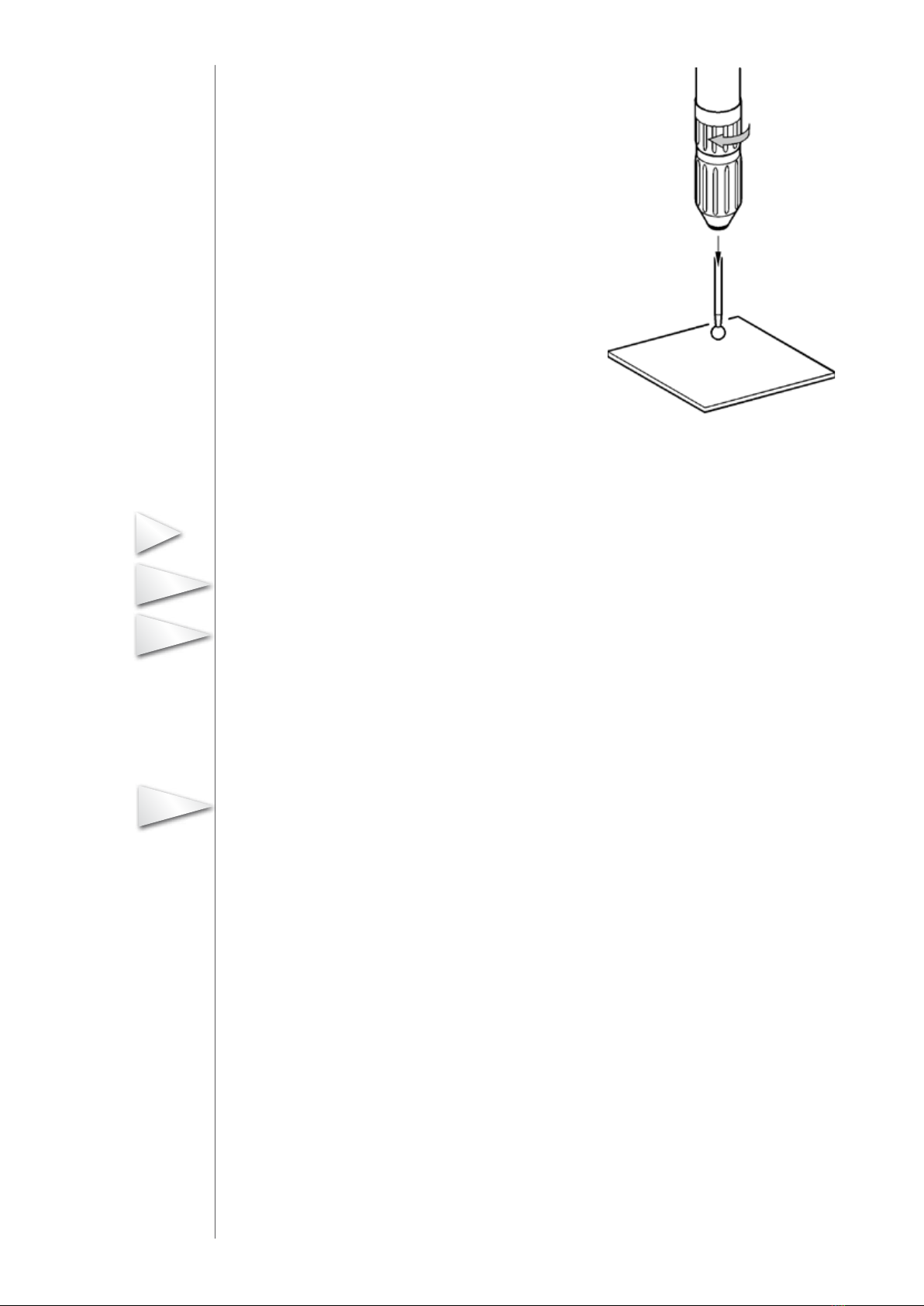
9. Wear safety goggles when working with the handpiece.
10. Personnel undergoing training or in a general apprenticeship should only be allowed to
work with the machine under the constant supervision of an experienced opera-tor!
11. Restrain from any type of work that could jeopardise your safety.
12. The device may only be used if all protective and safety equipment is in place and in proper
working order.
13. Do not leave the device unattended when switched on!!
14. Stop and secure the device immediately in the event of malfunctions! Faults must remedied
at once.
Warranty/ Identification
joke Technology GmbH warrant the correct manufacture of every joke product which is delivered in
accordance with the terms of contract and supply.
This warranty does not cover damages caused by normal wear and tear, incorrect handling, negli-
gent use, the fitting of non-original spare parts, inadequate care and/or a failure to comply with this
technical manual.
The device may only be used by appropriately trained personnel. If it is not, all warranty claims will
be forfeited according to the terms of supply.
Device identification
The manufacturer’s code and type code, CE label and series number can be found
• ontherearofthehousingandontheheadsectioninthecaseofthehandpieces
• ontherearofthehousinginthecaseofthemaintenanceunit
• andonthebottomsideofthefootswitch.
Disposal
This product shall not be treated as household waste. Instead it shall be handed
over to the applicable collection point for the recycling of electrical and electonic
equipment.
03
4
Important
Important
Caution
Caution

Device overview
The ultra-light, compressed air-driven high-speed handpiece P320-2 is designed for grinding and
milling. Only precision diamond tools and tungsten carbide burs approved for the handpiece may
be used in this case.
Approved tools
Refer to joke catalogue “Grinding, polishing and deburring tools”.
Fig. 5.1 High-speed handpiece P 320-2
1 - Head section (tool receptacle with bearings)
2 - Air outlet
3 - Air slits for cleaning the head
4 - Key flats for unscrewing the head section
5 - Tool unlocking ring
6 - Grip sleeve
7 - Hose connection
04
5
2
1
3
5
7
6
4

Scope of supply
Fig. 5.2 Overall scope of supply
1 – Maintenance unit with pressure reducer and water separator
2 – Foot switch
3 – Handpiece P320-2 with rest
4 – Air hose for handpiece
5 – Compressed-air supply hose for maintenance unit
6 – Fixing screws for wall installation
7 – Auxiliary tool for inserting a sharp tool
8 – Tool set
9 – Hose coupling for compressed-air hose
10 – Locking ring
05
1
2
3
4
5
78
9
10
6

11
12
Design of the device
Fig. 5.3 Design (symbolic drawing)
1 – Rotary knob for compressed-air adjustment
2 – Pressure gauge
3 – Air filter/water separator
4 – Handpiece P320-2
5 – Handpiece receptacle
6 - Air hose, handpiece
8 – Foot switch
9 – Air hose, foot switch
10 – Compressed-air hose
Functional principle
The high-speed handpiece P320-2 is driven by compressed air. The rotational speed of 320,000 rpm
provides the necessary cutting speed, even with the smallest tool diameters.
The turbine drive is equipped with encapsulated bearings.
Additional lubrication with oil mist must not be performed.
Owing to the low weight of the handpiece, sensitive work on the smallest components is possible.
Air outlet drill holes are provided on the head section of the handpiece, through which the filings are
blown away from the workpiece during operation.
Furthermore, the spindle is equipped with a patented “Clean-Head” keep-clean system to ensure
that ingress of soiling is safely prevented during operation.
The tool is changed by means of a rapid-chuck device in the head section.
06
Important

Technical data
Drive
Filtered compressed air (oil-free) . . . . . . .. . . . . . . . . . . . . . . . . . . . . . . .. . 0.2 MPa (max. 0.25 MPa)
(1MPa corresponds to 10 bar)
Quantity of air . . . . . . . . . . . . . . . . . . . . . . . . . .. . . . . . . . . . . . . . . . . . . . . . . . . . . . . . . . . . . .. . . . .40 l/min.
Performance data
Speed. . . . . . . . . . . . . . . . . . . . . . . . . . . . . . . . . . . . . . . . . . . .. . . . . . . . . . . . . . . . . . . . . 320,000 rpm
Torque . . . . . . . . . . . . . . . . .. . . . . . . . . . . . . . . . . . . . . . . . . . . . . . . . . . . . . . . . . . . . . . . . . . . . . . 12 N cm
Device control
Actuation of the devive . . . . . . . . . . . . . . . . . . . . . . . . . . . . . . . . . . . . . . . . . . . . . . . . . . . . . . Foot switc
Speed setting. . . . . . . . . . . . . . . . . . . . . . . . . . . . . . . . . . . . . . . . . . . . . . . . . . . . . . . . . . via pressure reducer
Dimensions and weights
Handpiece
Diameter . . . . . . . . . . . . . . . . . . .. . . . . . . . . . . . . . . . . . . . . . . . . . . . . . . . . . . . . .. . . . . . . . . . 16.6 mm
Length . . . . . . . . . . . . . . . . . . . . . . . . . . . . . . . . . . . . . . . . .. . . . . . . . . . . . .130 mm
Weight without hose. . .. . . . . . . . . . . . . . . . . . . . . . . .. . . . . . . . . . . . . . . .. . . . . . . . . . . . . . . . 70 g
Length of air hose to handpiece . . . . . . . . . . . . . . . . . . . . . . . . . . . . . . .. . . . . . . .. . . . . . . . .. . 2 m
Length of air hoses to foot switch . . . . . . . . . . . . . . . . . . . . . . . . .. . . . . . . . . . .. . . . . . .. . . . 2 m
Maintenance unit
Width x height x depth . . . . . . . . . . . . . . . . . . . . . . . . . . . . . . . . . . . . . . . . .. . . . 115 x 160 x 100 mm
Weigh . . . . . . . . . . . . . . . . . . . . . . . . . . .. . . . . . . . . . . . . . . . . . . . . . . . . . . . . . . . . .. . . . 720 g
Ambient data
Sound pressure level . . . . . . . . . . . . . . . . . . . . . . . . . . . . .. . . . . . . . . . . . . . . . . . . . .. . . . < 70 dB (A)
07
6

Operation
Device setup and connection
1. Set up the maintenance unit or secure it to the wall or workbench.
2. Push-fit the hose for external air supply on to the maintenance unit. By briefly pulling rear-
wards, the hose is safeguarded against disconnection (Fig. 7.1).
Fig. 7.1 (symbolic drawing)
3. After installing the hose coupling, connect the other end of this hose to an external com-
pressed-air hose.
4. Connect the two hoses of the foot switch to
the connections (A) of the maintenance unit (Fig. 7.2).
Unscrew the union nuts and push on to the
hose. Push-fit the hose ends on to the
connections before retightening the union nuts.
In doing so, take care that the hose marked
number 1 is located on the likewise numbered
connection piece (1).
Fig. 7.2 Rear view
5. Plug the hose for the handpiece on to the maintenance unit and secure by
pulling rearwards. Push the locking ring (Fig. 7.2/10) on to the hose beforehand.
08
7
Important
A

Push-fit the other end with the locking ring on to the connection on the handpiece (Fig. 7.3)
Fig. 7.3 Connecting the hose to the handpiece P 320-2
By briefly pulling rearwards, the hose is firmly anchored by the locking ring against disconnection.
The handpiece locking ring is enclosed in the packaging.
Performing a test run
The pressure controller is set to zero at the factory. Once the air supply has been connected, slow-
ly turn the knob clockwise in order to maintain a pressure of 0.2 MPa.
1. Firmly push the test mandrel for the test run into the handpiece receptacle
2. Pull up and turn the controller knob to unlock. After adjusting the nominal value, depress the
knob again to lock.
3. Operate the foot switch to switch the handpiece on and off and in order to check perfect opera-
tion.
Refer to section 8 in case of malfunctions.
Using the handpiece P 320-2 for the first time 7.4 (symbolic drawing)
1. Firmly push the selected tool into the handpiece
receptacle (Fig. 7.4).
Only use an approved tool with a shaft dimension of
ø 1.6 mm according to the joke catalogue!
Press the tool on to a firm base while doing so.
With a sharp tool, use the auxiliary tool for holding.
2. Operate the foot switch to switch the handpiece on and off.
Adjust the tool speed if necessary by regulating the air
pressure at the rotary knob on the pressure reducer.
09
Info
Info
Important
Caution
Info

3. In order to expel the tool, turn the unlockingring on the
handpiece anticlockwise to the stop position (Fig. 7.5).
Fig. 7.5 (symbolic drawing)
Notes on operation
The recommended air pressure for operating the handpiece is 0.2 MPa. A higher pressure may result
in failure of the bearing. The handpiece does not require any additional lubrication.
Do not use any lubricants!
Only apply light pressure when grinding and milling with the handpiece. Heavy soiling accumula-
ted during work may destroy the bearing and the tools. Pay attention to the permitted cutting speeds
and the tool manufacturer’s guidelines before using the tools.
Check that the tool is firmly seated and securely tighten the collet using the prescribed keys (refer to
Care/maintenance section).
Check the maintenance unit regularly. If condensation water and dirt are present, drain off the con-
densation water and clean the filter (refer to Care/maintenance section).
Wear protective goggles when working!
10
Important
Caution
Info
Important

Troubleshooting
Fault Possible cause Remedy
Tool does
not rotate.
•Footswitchnotdepressed. » Operate foot switch.
•Hosesloose. » Firmly push-fit/secure hoses.
•Colourcodingreversedwhenpush-
fitting the foot switch hoses.
» Push-fit observing identical colours.
•Airpressurecontrollernotopenedon
the console.
» Adjust pressure controller to 0.2 MPa.
•Colletfaulty. » Replace collet.
•Bearing/turbineinheadsectionfault. » Replace head section.
•Maintenanceunitfaulty. » Replace maintenance unit.
Tool cannot
be clam-
ped.
•Colletfaulty. » Replace collet.
Care
Clean all parts if required with a soft brush/paintbrush or a dry cloth.
Maintenance
Replacing the collet
1. Screw the head section out of the handpiece using an open-jaw wrench.
Fig. 9.1 (symbolic drawing)
2. Firmly hold the rotor of the head section, apply the chuck key to the
square flats of the collet nut and
screw out the collet nut (Fig. 9.2).
Fig. 9.2 (symbolic drawing)
11
8
9

3. Withdraw the guide bush located behind the collet nut (Fig. 9.3).
Bild 9.3 (Symbolzeichnung)
4. Screw out the collet using the tool or push out from the rear using the test mandrel (Fig. 9.4).
Fig. 9.4 (symbolic drawing)
5. Replace or clean the collet und collet receptacle.
6. Reinstall the collet and collet receptacle in the same manner in reverse order.
Pay attention to the exact arrangement and position of the components according to the drawings
when assembling the collet receptacle, guide bush and collet nut!
Draining condensate from the air filter
1. Render the device free of pressure.
2. Loosen the union nut of the bleed valve on the condensate reservoir of the maintenance unit by
unscrewing anticlockwise and subsequently pressing in and al-low the condensate to run off.
Fig. 9.5 Condensate reservoir
3. Subsequently clean the maintenance unit.
4. After emptying completely, retighten the setscrew by screwing clockwise.
Replacing the air filter
1. Render the unit free of pressure.
Remove the housing by removing the screws on the rear and the nut on the control valve!
2. Screw off the condensate reservoir.
3. Screw out the air filter and replace.
12
Important
Important

Take care that the filter socket and the loose seal are reinstalled with their position unchanged.
Fig. 9.6 Rear and bottom side of the maintenance unit
4. Screw in the condensate reservoir and perform a functional test.
Tools
Only the tools listed in the table are permitted for trouble-free operation of the handpiece P320-2.
A risk of injury by breakage of the tool exists if other tools are used!
Tools for a handpiece with a 1.6 mm collet
- shaft diameter of the tool 1.6 mm -
The tools listed below are constantly being updated. Please consult the current catalogue or the
Internet or joke directly.
Precision diamond tools (Grit D 126) Total length Order no.
Ball, Ø 1.00 mm 19 mm 0 560 570
Ball, Ø 1.60 mm 19 mm 0 560 571
Ball, Ø 2.10 mm 19 mm 0 560 572
Wheel Ø 1.8 mm x 0.70 mm 19 mm 0 560 573
Pear Ø 1.00 mm x 2.00 mm 19 mm 0 560 574
Cylinder, Ø 1.00 mm x 4.00 mm 19 mm 0 560 575
Cylinder, Ø 1.80 mm x 4.00 mm 19 mm 0 560 576
Rounded cylinder, Ø 1.40 mm x 4.00 mm 19 mm 0 560 577
Cone, Ø 1.20 mm x 10.0 mm 19 mm 0 560 578
Cone, Ø 1.60 mm x 10.0 mm 19 mm 0 560 579
13
Important
Important
Caution
Info
10

Tools for a handpiece with a 1.6 mm collet (shaft diameter of the tool 1.6 mm)
Precision diamond tools (Grit D 46) Total length Order no.
Ball, Ø 1.00 mm 19 mm 0 560 580
Ball, Ø 1.60 mm 19 mm 0 560 581
Ball, Ø 2.10 mm 19 mm 0 560 582
Pear Ø 1.00 mm x 2.00 mm 19 mm 0 560 584
Cylinder, Ø 1.00 mm x 4.00 mm 19 mm 0 560 585
Cylinder, Ø 1.80 mm x 4.00 mm 19 mm 0 560 586
Rounded cylinder, Ø 1.40 mm x 4.00 mm 19 mm 0 560 587
Cone, Ø 1.20 mm x 10.0 mm 19 mm 0 560 588
Cone, Ø 1.60 mm x 10.0 mm 19 mm 0 560 589
Tungsten carbide burs Total length Order no.
Ball, Ø 1.80 mm 19 mm 0 502 201
Ball, Ø 1.80 mm 19 mm 0 502 202
Ball, Ø 2.30 mm 19 mm 0 502 203
Rounded cylinder Ø 1.40 mm x 4.40 mm 19 mm 0 502 204
Cylinder, Ø 1.40 mm x 6.00 mm 21 mm 0 502 205
Conical, Ø 1.20 mm x 4.20 mm 19 mm 0 502 206
Conical, Ø 1.60 mm x 6.00 mm 19 mm 0 502 207
Tungsten carbide burs with tita-nium nitride coating Total length Order no.
Pear, Ø 1.80 mm 19 mm 0 502 210
Cylinder, Ø 1.00 mm x 4.20 mm 19 mm 0 502 211
Conical, Ø 1.20 mm x 4.20 mm 19 mm 0 502 212
Rounded cylinder Ø 1.20 mm x 4.20 mm 19 mm 0 502 213
Conical, round , Ø 1.20 mm x 4.20 mm 19 mm 0 502 214
14

To the
joke Technology GmbH-Service department
+49 (0) 22 04 / 8 39 - 86
Sender:
Company
Name/department
Customer no.
Street
Postcode / Town or city
Please send us the spares drawing and parts list for the following equipment:
as a print (see above for address)
by fax,
as a pdf file to my email address
Eneska high-speed handpiece P320-2 Order No. 0 009 900-0
Handpiece P320-2 Order No. 0 009 901
Head section, complete Order No. 0 009 902
Collet, 1.6 mm Order No. 0 009 909
Foot controller Order No. 0 009 916
Maintenance unit, (without handpiece and foot controller) Order No. 0 009 936
Date Signature
11

Surface Technology
Oberflächentechnik
joke Technology GmbH
Asselborner Weg 14 - 16
D-51429 Bergisch Gladbach
Telefon: 022 04 / 8 39-0
Telefax: 022 04 / 8 39-60
Internet: www.joke.de
E-Mail: [email protected]
All rights reserved for modifications due to technical progress.
joke 02/11
This manual suits for next models
1
Table of contents
Other joke Grinder manuals
Popular Grinder manuals by other brands

Rhyas
Rhyas BGM4006 Original instructions

Parkside
Parkside PWSAP 20-Li D4 Translation of the original instructions

Bosch
Bosch GGS Professional 8 CE Original instructions

NorthStar
NorthStar M296026C owner's manual

Westfalia
Westfalia 84 31 15 instruction manual

Atlas Copco
Atlas Copco G2515 Original product instructions